Week8- Embedded Programming
Assignment
group project:
- compare the performance and development workflows for other architectures
individual project:
- read the data sheet for your microcontroller use your programmer to program your board to do something
- extra credit: try other programming languages and development environments
Group assignment
Basics on microcontroller
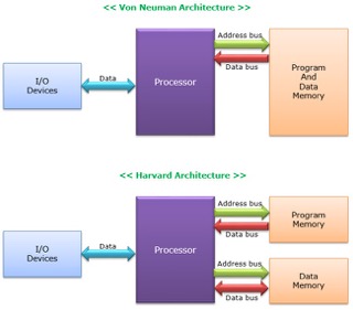
Comparison between Von Neumann and Harvard
The microcontrollers that are in the fablab uses harvard artitecturer and is faster compared to Von Neumann artitecture.
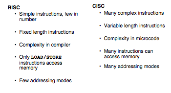
Comparison between RISC and CISC
We use RISC artitecture during the course of fabacademy which uses simple instruction to execute one at a time but is very fast. #Note
- RISC= Reduced Instruction Set Computer
- CISC= Complex Instruction Set Computer
Comparing different Microcontrollers
1. ATtiny44
Features of ATTINY44:
- 8bit
- 14 pins
- RISC architecture
- 32 x 8 General Purpose Working Registers
- Memory: 4K Flash Program Memory, 256 B EPROM and 256 B SRAM
- Peripheral Features
- One 8-bit and One 16-bit Timer/Counter
- 10-bit ADC
- Programmable Watchdog Timer
- On-chip Analog Comparator
- Universal Serial Interface
- Special features- debugWIRE On-chip Debug System
- I/O and Packages: 12 Programmable I/O Lines
- Operating Voltage: 1.8 – 5.5V
Pin-configuration
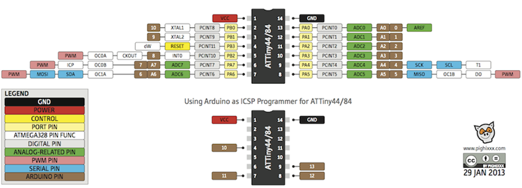
Pin description
- VCC- supply volatge
- GND- Ground
- Port (PA7:PA0)
- Port B (PB3:PB0)
- RESET- PB3
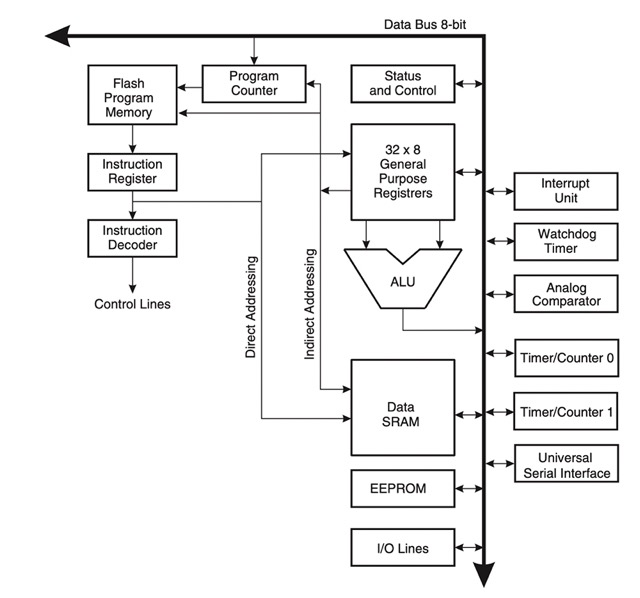
Architectural overview
The ATtiny44 microcontroller uses Harvard architecture
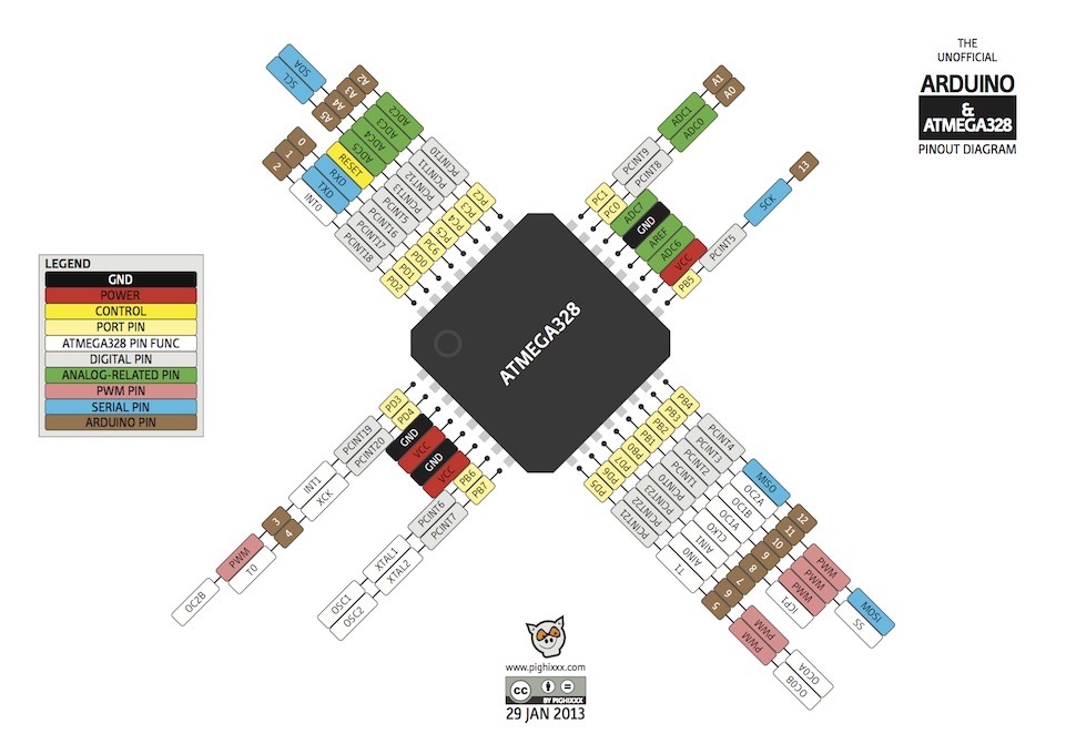
2. Atmega328P
The atmega328P is the microcontroller in the popular Arduino Uno. The datasheet for this microcontroller is linked here
It is 300 pages long so I skimmed over the most important bits. Here are some key takeaways: It is an 8 bit microcontroller belonging to the AVR family. RISC architecture Memory 32KBytes ISP flash program memory 1KBytes EEPROM 2KBytes Internal SRAM Write/Erase Cycles: 10,000 Flash/ 100,000 EEPROM Peripheral Features Programmable serial USART Interrupt and wake-up on pin change Operating voltage: 2.7V to 5.5V for ATmega328P Low power consumption Active mode: 1.5mA at 3V - 4MHz Power-down mode: 1µA at 3V
Pinout:
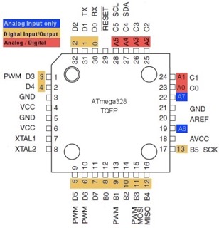
Pin Description:
-
Vcc and GND must be connected for power supply
-
Port B
-
8 bit bi-directional I/O port
-
There are 8 pins in this port (PB7:0) from my understanding, Port B is mainly used for special connections like MISO, MOSI, XTAL1, and XTAL2. These connections go to the AVRISP header and the resonator.
-
-
Port C
- 7-bit bi-directional I/O port with internal pull-up resistors
- 5 pins in this port (PC5:0)
-
PC6/RESET
- Reset input pin
-
Port D
- 8-bit bi-directional I/O port with internal pull-up resistors
- There are 8 pins in this port (PD7:0)
-
AVcc
- AVCC is the supply voltage pin for the A/D converter, PC3:0, and ADC7:6.
- It should be externally connected to VCC, even if the ADC is not used.
- If the ADC is used, it should be connected to VCC through a low-pass filter.
-
AREF
- the analog reference pin for the A/D converter.
-
9 ADC7:6 (TQFP and QFN/MLF Package Only)
- In the TQFP and QFN/MLF package, ADC7:6 serve as analog inputs to the A/D converter. These pins are powered from the analog supply and serve as 10-bit ADC channels.