Molding and Casting - Attempt #1
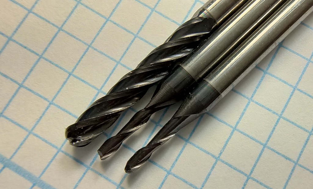
Spoiler alert: Have you ever seen these milling bits? Remember their faces, they will come to hunt us down, later. 😱
Individual Assignment:
- design a mold around the stock and tooling that you’ll be using ✅
- mill it (rough cut + three-axis finish cut) ✅
- and use it to cast parts ✅
- extra credit: use more than two mold parts
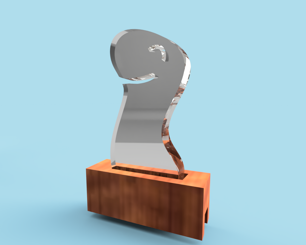
Concept - Render
This week, we were asked to build a cast.
** Inspiration**: Dinosaurs playing hide & seek - comic
Material, datasheets and properties
Stock
- Recycled Machinable Wax
- Dimensions:
- Width: 143mm
- Length: 85mm
- Depth: 43.9mm
Milling Bits
| Cut Type | Diameter | Flute Count | Cut | Flute length | End-mill | Shank diameter | Shoulder height |
|---|---|---|---|---|---|---|---|
| Roughing | 3.179 mm (1/8th inch) | 4 | Up-cut | 19mm | Flat | 3.179 mm | N/A |
| Finishing | 1.55mm (1/16th inch) | 2 | Up-cut | 6.5mm | Flat | 3.17 mm | 10 mm |
| Finishing | 1.55mm (1/16th inch) | 2 | Up-cut | 6.5mm | Ball | 3.17 mm | 10 mm |
Silicone
- Box labels:
- Commercial Name: Easyplat 00-30
- Material: Translucent Platinum Cure Silicone
- Shore hardness: 00-30
- Viscosity: Very low
- Working time: 35min (at 25 ºC)
- Curation (Demoulding) time: 4h (at 25 ºC)
- Components:
- Parts: 2 parts
- Part A: Dry Powder
- Part B: Dry Powder
- Mixing: mix both parts using a 1:1 ratio (50% of each) by either weight or volume
- Other technical properties:
- Tensile strength: 4.5 +- 1.0 MPa
- Viscosity of the mixture:: 3000 +- 1000 mPa.s
- Tear strength: 8 +- 3 kN/m
- Shrinkage: <0.1%
- Data Sheets:
Epoxy
- Never decided. Never used 🤷 This piece was never cast. Jump to “casting 2nd attempt” page, if you want to see a finished piece.
Designing the piece
A common mistake while designing molds is to simply extrude perpendicularly. This works for tasks but will prove difficult during mold manufacturing in 2 different moments:
- ⚠ During milling, if the milling bit encounters a vertical wall and accidentally hits it with the shank or any other
non-cutting part, it might drag the piece along instead of cutting. This has several risks:
- Breaking the milling bit (if it’s fragile) = buy a new milling bit, and restart the job.
- Moving the stock a bit, if it’s not attached strongly to the bed = restart the job
- Send the stock flying off = damage up to potentially breaking the CNC, milling bit, and restart the job.
- ⚠ During the casting process, when we try to remove the cast from the mold, it might cause excessive friction and make the process unnecessarily difficult and fragile.
If we use tapered walls/extrusions (in all the places where it is reasonable and where it does not interfere with our design), we can prevent all of these issues.
Toolpaths
In order to produce our mold, we will use the Roland SRM-20 milling machines in our workshop.
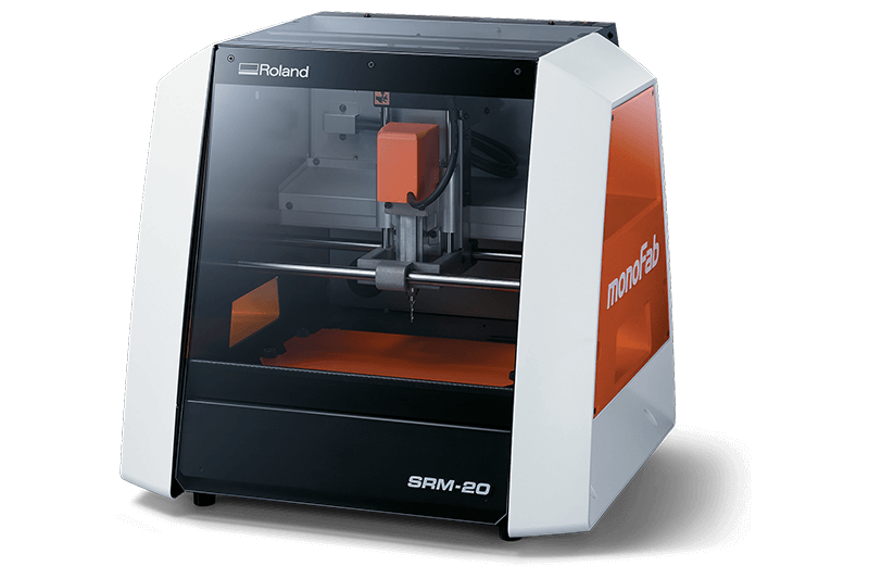
These devices come with Modela Player 4, a piece of software that can be used to create 3D tool-paths for milling.
We will create various toolpaths using different mill bits.
Roughing toolpath
During subtractive manufacturing processes, the purpose of the roughing cut is to remove the vast majority of the material. The toolpath will get close enough to the actual piece (up to a safety distance that we configure) but will always leave a bit of material behind, that we’ll remove un subsequent passes with finer tools.
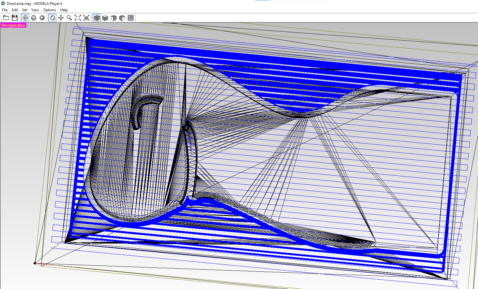
The tool is large enough to leave very distinct marks and passes when we visualize the toolpath.
1st Finishing toolpath
The Finishing cuts are there to remove the last bits of materials left behind from the roughing cut.
They trade-off slower speed for better precision and better cuts, curves and surfacing precision.
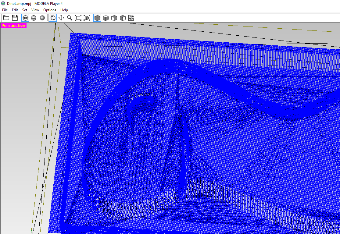
The preview of the toolpath shows how much more precision this cut will use.
Don’t let these two pictures fool you, though. Normally the longest cut is the roughing one, because it needs to do multiple cuts at different depths (they just get stacked in the preview).
The finishing cut is not as slow as it seems, as it only covers the surface of the piece.
2nd Finishing toolpath
Some processes can use more than 1 toolpath for each type, for example to use different milling bits and allow the operator to swap them between runs.
In my case, I also added a 2nd finishing cut with a ball end-mill, for even smoother surfaces.
You can find the toolpaths in the Assets section at the end of the doc.
Milled piece
This is what the piece looks like after the end of the initial roughing cut.

You should notice:
- There are 2 parts of the surface that were not touched by the roughing mill.
- This is because the roughing end-mill would have to break the safety distance (0.4mm) in order to come that close.
- This part is going to be cut using the finishing cuts (which have no min. safety distance, of course).
- The mouth and eyes have very low definition
- Same reason as above. The 3mm flat end-mill used for roughing only went i on the parts that had a clearance large enough.
- Despite being only a rough cut with the largest bit ( > 3.1mm), the wax chips are still fairly small and easy to make them fly away.
Lessons learned - ⚠ Problems during the milling process
Unfortunately, there were some problems during the milling process.
The walls were chamfered, but not enough for the finishing endmill I used for finishing-1 cut.
If you check the picture at the beginning of the page, you will see that the finishing endbits have a thick shoulder that is much wider than the flute diameter.
Hypothesis
My working hypothesis is that, despite the walls being not vertical (10 degree chamfer), the roughing cut is still making the “rough” cut vertical for some unknown reason.
The secret hope is to blame this on the software designed by a multimillion dollar machine manufacturer, instead of me, a first time mold designer.
Let’s see who wins! 😅
Proposed working methodology
- Analysis method #1: I could install Modela Player 4 on my laptop and try to open the toolpath.
- This was discarded because I don’t have a license. and right now I’m on Linux and I don’t feel like rebooting into Windows.
- Analysis method #2: Post morten analysis of PRN Code to see how the tool actually moved.
- Cons: Heavy and boring spreadsheet use (45 min of spreadsheet fun)
- Pros: Not having to boot into Windows. Not having to find out if the software actually requires a license.
- Pros: I get to revive and remember trigonometry lessons from years ago!
- Yay, Matilde… May this documentation be a sanctuary devoted to the best maths teacher I ever had!
- Cons: It is 2AM, and I’m still writing about this, instead of just finishing this documentation.
PostMortem Analysis
The first step is finding an X position that repeats over time.
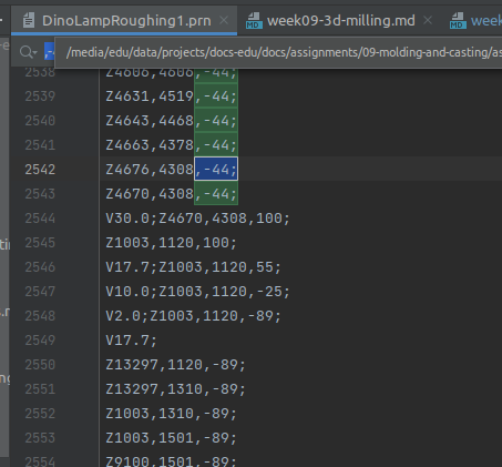
Hint: We can use a text editor that supports multi-line regular expressions searches.
This coordinate seems like a good place to start.
You can see that the file has multiple repetitions evenly spread, and they all target the same X and Y, but different Z coordinates. We deduce that this is one of the milling passes that remove lots of layers of material.
Here are some of the bits we’re interested in:
File preamble skipped
...
Z13297,1120,-44;
Z13297,1310,-44;
Z1003,1310,-44;
Z1003,1501,-44;
Z9117,1501,-44;
V30.0;Z9117,1501,100;
Z10823,1501,100;
V10.0;Z10823,1501,20;
... Skipped to the next depth down 0.44mm deeper
Z13297,1120,-89;
Z13297,1310,-89;
Z1003,1310,-89;
Z1003,1501,-89;
Z9100,1501,-89;
Z9098,1501,-89;
Z9038,1512,-89;
... Skipped to the next depth down 0.44mm deeper
Z13297,1120,-1067;
Z13297,1310,-1067;
Z1003,1310,-1067;
Z1003,1501,-1067;
Z8759,1501,-1067;
Z8587,1542,-1067;
Z8517,1561,-1067;
Z8516,1561,-1067;
Z8406,1591,-1067;
... Skipped to the next depth down 0.44mm deeper
Z13297,1120,-1111;
Z13297,1310,-1111;
Z1003,1310,-1111;
Z1003,1501,-1111;
Z8745,1501,-1111;
Z8580,1541,-1111;
Z8577,1542,-1111;
Z8467,1571,-1111;
Z8256,1631,-1111;
Z8255,1631,-1111;
...
Rest of the file also skipped
You can download the original PRN file from assets
It is very clear what’s happening, right?
But, just in case you are not a lecturer in FabAcademy, we’ll do a small breakdown:
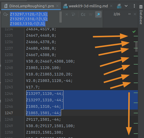
This is the output after a fun (and arduous) Post-Mortem Analysis for the PRN Code.
First, some summary: We wanted to perform our analysis on various cuts (at the same X/Y positions, but at different depths), and then compare how/if the X and Y are changing, as we cut deeper and deeper.
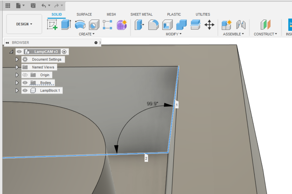
If our hypothesis is correct (🤞 fingers crossed) we should see that, as the mill goes deeper, the X and Y don’t change enough to respect the chamfer of the wall (that is… that it has an inclination close to 90 degrees, or, at least 80 degrees), 80 degrees of inclination would be what we put in our original design (except that the Fusion screenshot above shows it at 100 = 99.9 because I was measuring the opening of the angle instead of the inside angle).

The initial passes are looking promising (it seems that I will be able to blame this failure on Roland Co. Ltd, after all).
But, ah! Fatality!! If we compare a cut at the tallest point, with the same cut at a deeper depth, we will see that our hope vanishes really quickly.
A closer look confirms that our hypothesis is incorrect and that, despite initial looks, the PRN Code does leave enough room to avoid this problem.
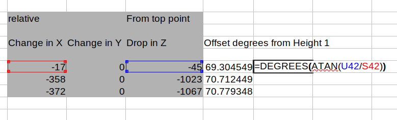
The angle of the rough cut is 70 degrees (even more open/safer than I originally designed), and the cause of this is that I did not account for the end-mill thicker shoulder during design.
Summary
- It seems that Modelo Player 4 does not have tool collision support.
- This puts the responsibility of checking the tool collision, and to design pieces accordingly, on us.
- This is not something I accounted for during design, and it caused the finishing end-mill to aggressively hump the piece of wax for about 30 seconds.
- Fortunately the end-mill survived to tell the tale.
Raw Postmortem Data
✨ Join the fun and download the full breakdown/spreadsheet
2nd attempt
Go to the 2nd Attempt to see how that went.