Electronics Production
Individual assignment:
- make an in-circuit programmer that
includes a microcontroller:
- mill and stuff the PCB ✅
- test it to verify that it works ✅
- extra credit: customize the design ✅
- extra credit: try other PCB processes
Basic premises:
- Boards are just containers for electronic circuits, their components, and their microcontrollers.
- You need a programmer board to program other boards.
- In reality, you don’t program the board: you program the microcontroller that is soldered to the board. In most cases, the microcontroller is the only device that’s smart/complex enough to have programmable behaviour.
- In this doc, we will be using “boards” / “programmable boards” / “programmable microcontrollers” interchangeably and synecdochically. (I love you, Erin McKean)
- “Programmer boards” are simply normal boards that have been programmed to act as “Programmers for other boards”.
- And that’s their only purpose in life. That’s all they will do.
- And they freaking love doing it! (or that’s what I’ve been told!)
Tasks, explained
Now that we have a list of tasks to complete, and a basic understanding of what's what, this is what we will attempt to build this week.
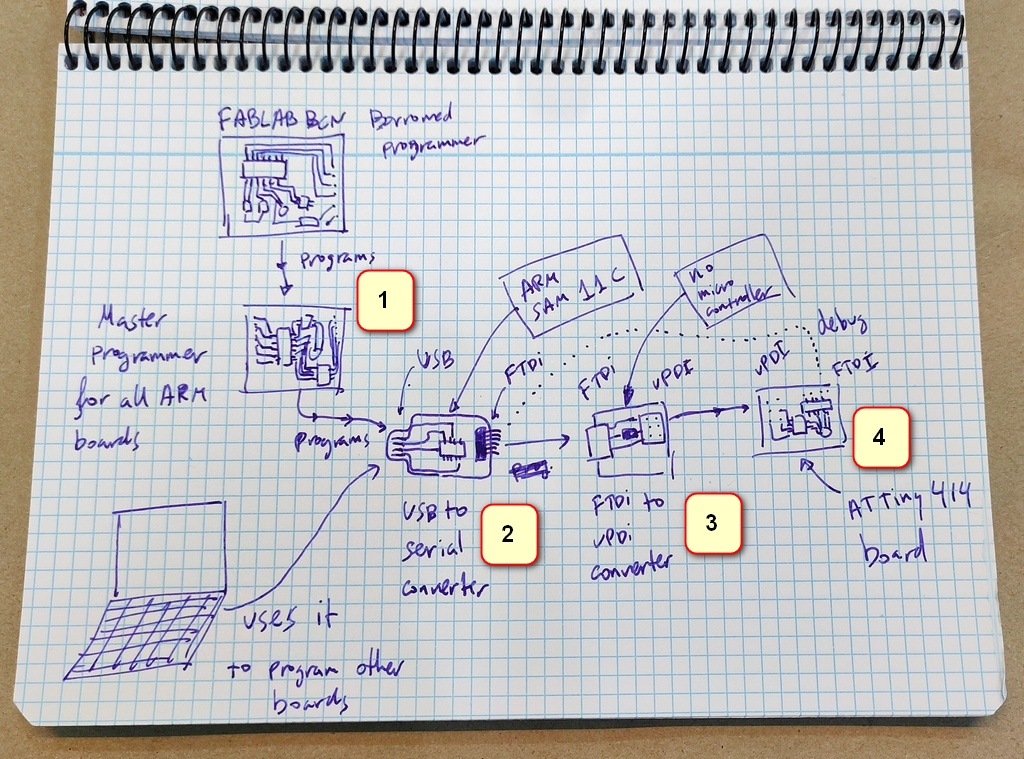
- A Master Programmer board1, which I will use to program any other boards over the rest of the course.
- And, based on what I've heard... there will be a lot of boards to create over the next few weeks, so the master board better be sturdy, stable, reliable and hard to break (non-functional requirement 😉).
- This board will use a SWD SAMD11C14 microcontroller
- An ARM based board2 that will be used as the programmer for our target board for this week's assignment.
- A target board4 based on the ATTiny XXXX
- This board will have 2 interfaces
- A UPDI programming interface, so we can load programs into it
- An FTDI debugging interface, so we can read values off of it and assess what exactly is going on inside.
- When we program it, over UPDI, we will use the adapter board3
- When we want to debug it, we can use the ARC SAC D11C2 directly.
- This board will have 2 interfaces
- An intermediary board3 that will work as an adapter from FTDI to UPDI
- This board will have no microcontroller and just acts as a "translator" between protocols
- We will only need it to program the target board, if the target board requires UPDI to be programmed.
With this ecosystem, we will have most of the tools we’ll require for the rest of the course.
Wait… how are you going to do this?
By now, if you’ve been paying attention, you will have noticed that there’s a major gap in this documentation.
How are you going to program the first board (the master programmer), if you need a programmer board to load its logic?
Ah, the eternal question: Who programmed the master programmer?
That’s right! We cannot program our master programmer without another programmer. In order to program our master programmer, we will borrow an existing programmer from the FabAcademy instructors, once. Once the first student programs their master programmer, other students can use that students’ master programmer to program their master programmers.
In environments where there is no “FabLab Instructor who has a master programmer on hand”, you should be able to buy a JTAG programmer and use that to program your master programmer.
The microcontroller ecosystem
(as seen by a newbie, for the first time)
The ecosystem seems very complex from the outside, and my head is melting after a short 1h intro to the field, but it seems that this complex topic will be slowly evolving over the next few weeks. Feeling overwhelmed is a normal and reasonable feeling. Don’t fight it! 😉
Choosing the boards
Download the design files from fabcloud
We are going to be building:
- SWD D11C as the master programmer
- Serial D11C as the Serial adapter
- a Serial to UPDI Adapter
- our target board basedo on ATTiny XXX
Milling the boards
Before we get started milling the SWD-D11C, we need to make some tweaks, because the traces file has a defect.
The black separation is too narrow which could cause problems when we will it, potentially causing shorts.
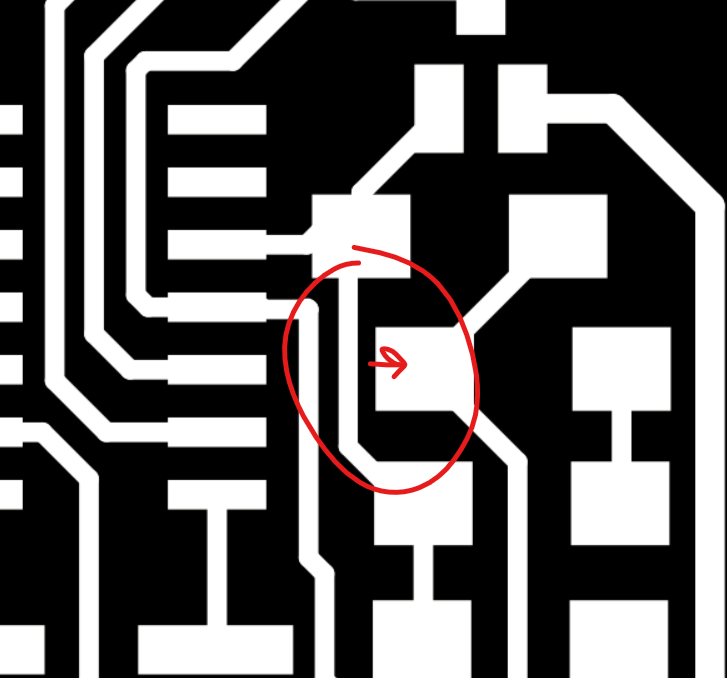
We have to widen the path to isolate both parts of the circuit properly.
So, let’s get to it!
Iteration 1
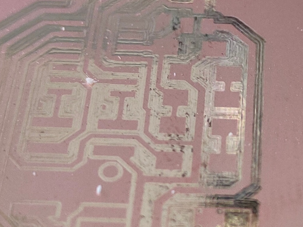
PROBLEMS: If you don’t set the Z low enough, you will get a really shiny and polished surface instead of milled traces on the board.
Z is set too high when attaching milling bit:
After adjusting the Z again, and doing a second pass:
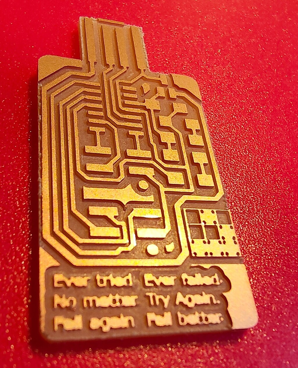
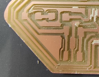
The result - my first milled board
Here’s a time-lapse of the milling process
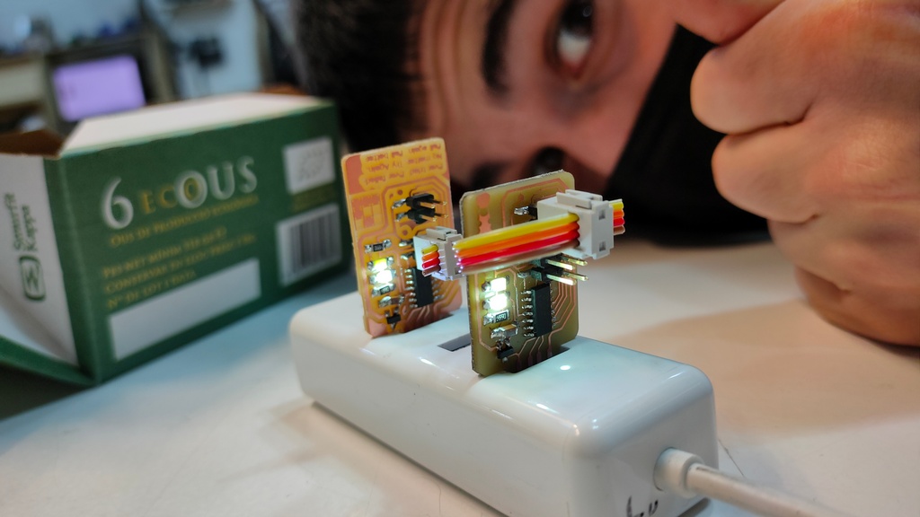
Soldering the components to the boards
Before we get to Soldering, allow me to present this week’s Emotional Seismograph
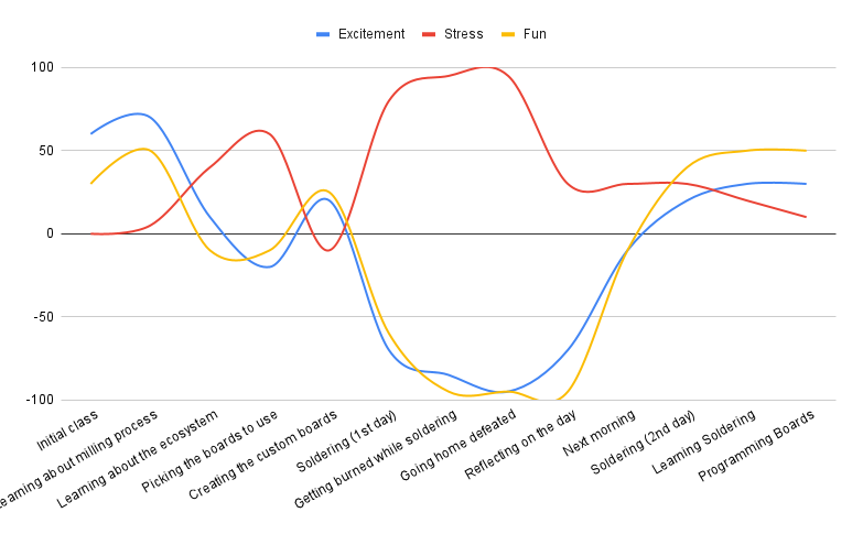
Alright! a lot to unpack here:
- The symmetry across the horizontal axis on the “stress vs fun/excitement” is so obvious that doesn’t even require further analysis.
- Getting burned while soldering is not fun.
- The burn was pretty not deep, but definitely intense, requiring 3 visits to the cold water tap over 15 minutes. The residual heat that the body had absorbed made the pain come back multiple times.
- Fortunately, it had a small surface, and the cold water application helped a lot.
- Lesson learned: Don’t leave the water tap too soon. Stay there for as long as you need it.
- The residual heat absorbed, made the skin a lot more sensible to heat. This meant that I could not solder for the last hour of the day, since just handling the solder close with my hand (so close to the would) was already awakening a sense of discomfort.
- It was a good idea to purchase a small pair of gloves. They are not ideal for soldering (they do retain heat), but
it’s better than nothing.
- Do FabLabs have soldering gloves?
- If not, how do we know what to look for when buying them?
- As a person with superb uncoordination between mind and body, having to handle a soldering iron and being asked to solder feels like having to wield a star wars laser saber during a tickling contest! Good luck everyone!
- And that’s for someone who doesn’t drink coffee!
Alright, now that we have this out of the way, let’s take a look at the finish boards.

As you can see, you can clearly see the progression from “first board to be soldered” to “3rd board soldered in my life” is obvious.
Programming the programmer
The last task to complete was to program the master programmer.
Since I used Adai’s board to program mine, I believe this makes him my legal guardian, or something!
Are there initiation rites or superstitions when it comes to programming boards?
EDBG - Atmel Embedded Debugger
In terms of programming, I used a command-line tool called edbg
from ataradov/edbg to burn the bootloader into my microcontroller.
This application is available for windows, linux and mac and supports all Atmel Embedded-Debugger-based board.
In my case, I downloaded the latest edbg binary from Taradov’s page, as well as the base image for my board (D11C) , which can be found in the official mattairtech/ArduinoCore-samd repository.

In future weeks, we’ll discover other ways to program board, both, using a programmer, and without needing one, as well as using arduino IDE instead of edbg directly (arduino will still use edbg behind the scenes, but it also supports other ways).
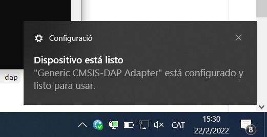
Success
The board seems to work when plugged into the laptop
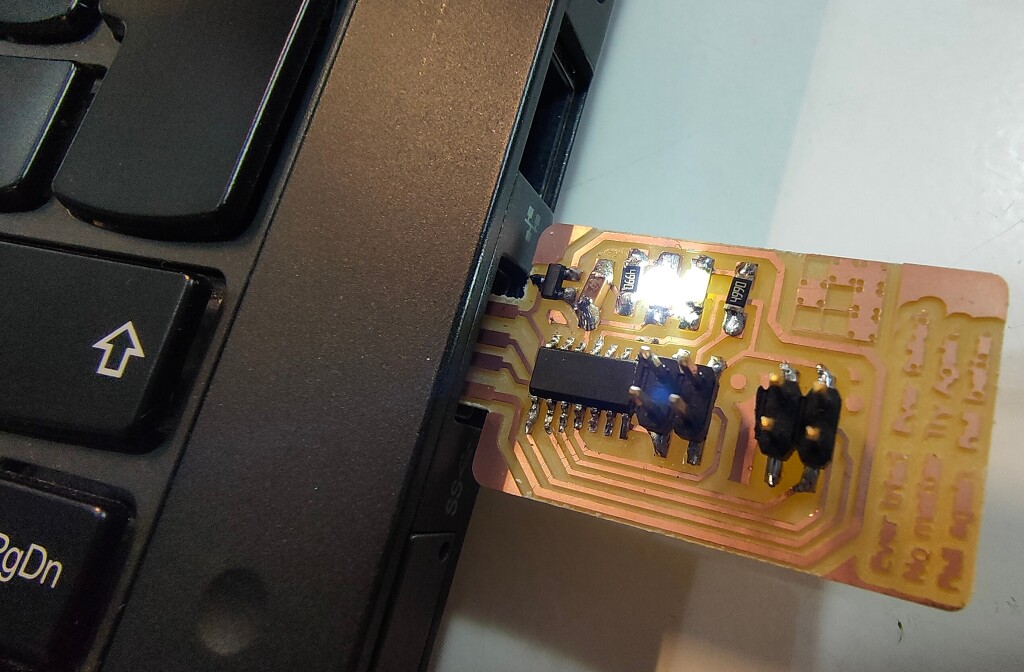
And it gets recognized as a USB device.
Nice USB handshake 🤝🏻, mate!
Lessons Learned
Loose milling bed
This is what a board looks like, if you fail to fix it properly to the the bed of the machine moves during milling.
Fix: Tighten the bed of the machine, so it does not move/shake/wobble during milling
Cheatsheet
Milling PCB traces using mods
In the barcelona FabAcademy we have a Roland SRM-20 mill, so we will use the settings for the program for that device.
- Right-click on the empty mods project. You will see a popup menu:
- select “Programs > Open Program” and pick our device from the list (Roland SRM-20 mill Absolute, in our case).
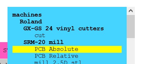
- Load the PNG using the bottom panel:
- Check that the resolution is 1000 DPI or similar
- Check that the sizes match the board you are about to print
- On the “Set PCB Defaults” panel at the top of the page:
- Check that the mill diameter matches what you will install in the machine (1/64 inch)
- Set the Speed to 3mm/s
- Click the “mill traces” button
- On the “Roland SRM-20 Absolute Coordinates”
- Set Speed to 3mm/s
- Set Jog Height to 7mm
- Set Origin to (0,0,0)
- Set Home to (0,0) and 10Z
- Connect the output of “Roland SRM-20 Absolute Coordinates” to the input of “Save File” panel
- This will allow you to download the tool path once it is calculated
- On the “Mill raster” panel
- Click “Calculate”
This will generate and download a file on your browser. Load this file into your Roland SRM-20 machine in order to print the traces onto the board.
Cutting the PCB outline using mods
Repeat the same steps with minor changes:
- Load the outline file instead of the traces file.
- Set “PCB Defaults”, look at the second section called “mill outline 1/32”
- set speed to 1.5mm/s
- Click on the header button “mill outline 1/32”
- on the “Mill Raster 3D” panel
- check that “offset number” is set to 1 instead of 4.
- set max depth to 1.75mm instead of 1.828mm
- In the “Roland SRM-20 Absolute Coordinates” panel
- Set speed to 1.5 instead of 3mm
✨ Automating these almost-perfect programs
As you can see, the steps above are “almost perfect”, but they are incorrect in a couple of critical places, which makes us carry a mental load that we’d rather not have to carry, every single day.
After hearing that we will be doing custom boards almost every week for each of the individual assignments, I decided to customize the script, and test it out, before sharing it with the wider community.
These are the customized programs for mods:
You can right-click and “save as” these files.
In order to use them, just import them into mods, using the “Programs > Open program from file”
WHY the effort?
Considering that a single mistake or forgotten setting will result in either:
- 1 broken board
- COST: around 0,20 EUR
- TIME: around 30 minutes of work lost that will need to be redone
- COMMUNITY: probably blocking other students from using the machine while we redo our work
- 1 broken milling bit
- COST: around 25 EUR for a new milling bit
- COMMUNITY: negative health consequences (one (1) heart attack per week, approx…) for each of our local instructors
- 1 unit of Psychological Safety in the lab
- I heard that some FabAcademy sites make students do a crazy dance or a ritual or repentance.
- I firmly believe that a culture of “acting/performing” as well as “public naming and shaming” are counterproductive to creating a learning and safe environment
- but, from my position as a student, fixing one script and sharing it widely can have a much bigger impact (and is easier than) fixing their local habits.
- Or maybe ALL three consequences combined (if they really unlucky)
Considering the cost of “forgetting one setting”, it starts to make sense to automate this step from our production process. Don’t you think?

Btw, if you are wondering which editor makes this work so easy (editing javascript that’s encoded INSIDE a non-prettified JSON file), the answer is IntelliJ IDEA.
I have been using it for 9+ years, and I love it.
Group Project
Assets

- swd-d11c_traces_customized.png
- swd-d11c_traces_customized.png.rml

- swd-d11c_outline_customized.png
- swd-d11c_outline_customized.png.rml
- edbg.exe - program used to flash custom bootloaders or binaries into atmel microcontrollers
- sam_ba_SAMD11C14A.bin a basic bootloader that supports loading programs via USB without requiring an external programmer board (after it is flashed once, with a master board!)