Computer Controlled Machining
A compression milling bit, used during our fab-lab’s safety training.
Individual assignment
- make (design+mill+assemble) something big (~meter-scale) ✅
- extra credit: don’t use fasteners or glue ✅
- extra credit: include curved surfaces

Initial render
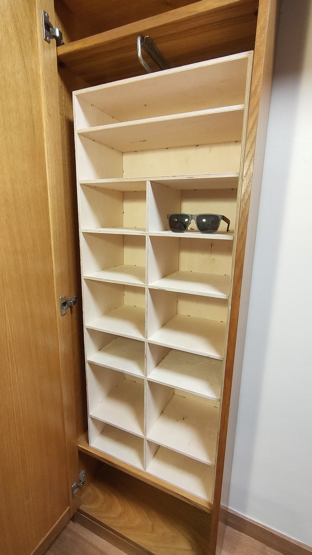
This week I decided to build something some storage space for my flat.

Fig1 - Initial Render
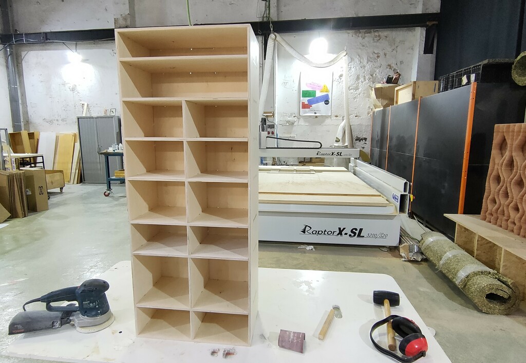
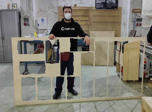
Fig 2 - The finished product
Design
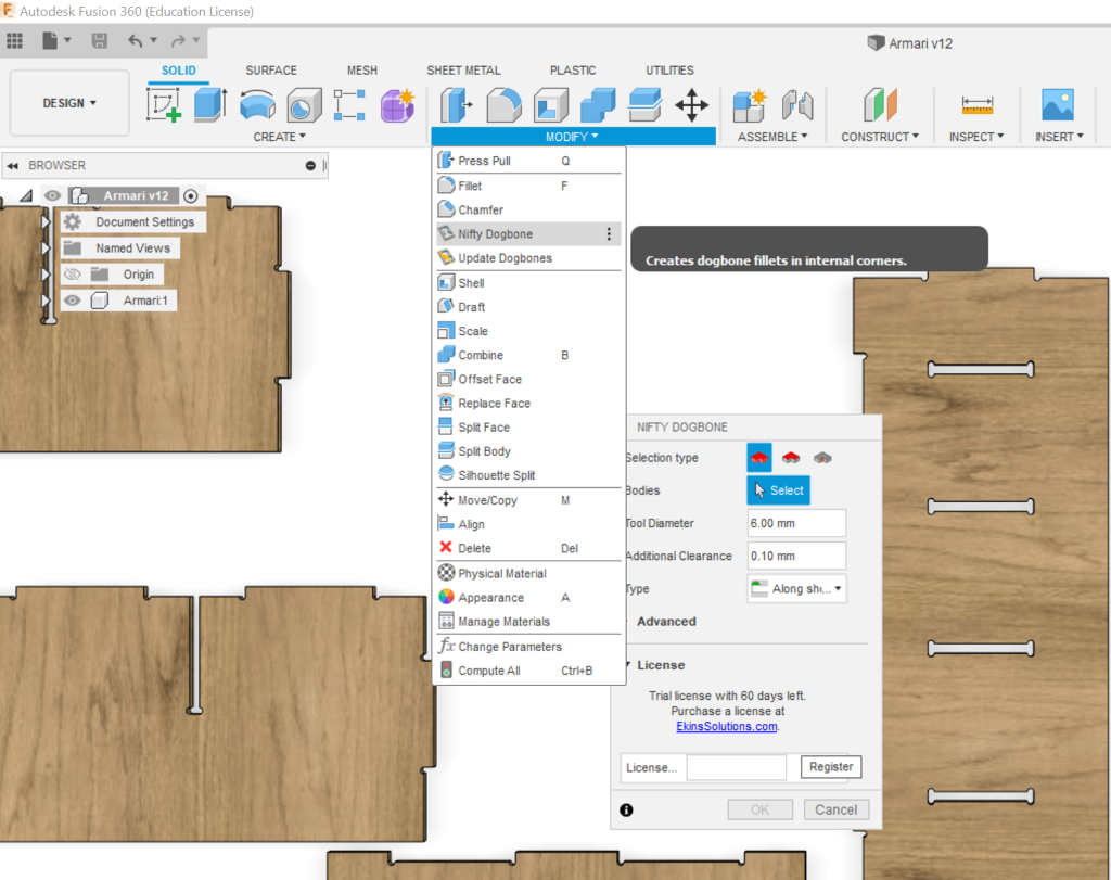
Adding dog-bones using the nifty-dogbones plugin for Fusion360
As with all CNC Milling jobs, our design needs to include dog-bones, so that the fittings are tight and solid.
I decided to use a Fusion360 plugin for this: nifty-dogbones.
The process was as painless as it could have been:
- Install the plugin (60 day trial)
- Restart Fusion360
- A new menu appears under “Modify”
- Click on Nifty Dogbones
- Select the bodies that you want to transform
- The plugin lets you specify the basic settings (tool diameter, tolerance, and the type of dogbones)
- Click “Ok”
- Done!
Absolutely flawless and completed in less than 5 minutes end-to-end.
✨ If you’re building more than 2 pieces of furniture per year, this is a must-have plugin. $20, for the full version, lifetime license, is definitely worth the money, considering the amount of time that it will save you over and over.
Check out the rest of the apps and plugins that Ekin Solutions has available.
(Yes, I’m leveraging the power and recognition of FabAcademy.org to boost this developer’s pagerank and visibility online. It’s not that obvious, is it?)
CAM in Fusion360
After the design was completed, I wanted to explore the CAM workflow using Fusion360.
The software seems to be well-equipped for this, but given the material constraints that I was working with (limited material, and very little room to spare), I had to nest all my components perfectly if I wanted them all to fit inside the single sheet of 9mm wood.
Unfortunately, I couldn’t find any powerful nesting support inside Fusion360, and I decided to default back to DeepNest.
I look forward to exploring CAM in Fusion360 in the future, if I ever have a design that requires little material, and simple nesting requirements.

Nesting the pieces
I used deep-nest in the past, and It worked really well.
This time, however, it struggled a bit, and it did a far-from-ideal job.
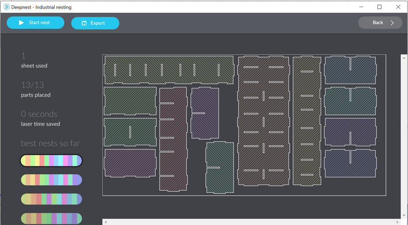
In the end I had to end up nesting the pieces myself manually in Rhino.
I believe that the reason why DeepNest struggled so much, is that it had very little material to work with.
The pieces almost utilized the entirety of the available board, and the struts/spaces we had to leave between the pieces (as holders) meant that there was not much spare room to work with.
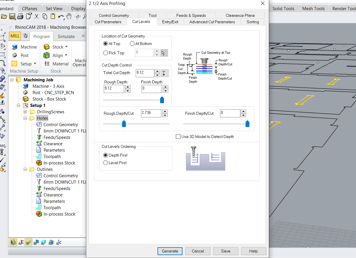
CAM in RhinoCAM
This week I used RhinoCAM to create the operations for milling these pieces.
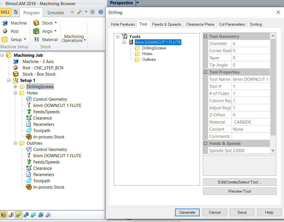
Drilling screw holes
We start by drilling some holes in our stock in order to prevent it from moving around during the rest of the operations.
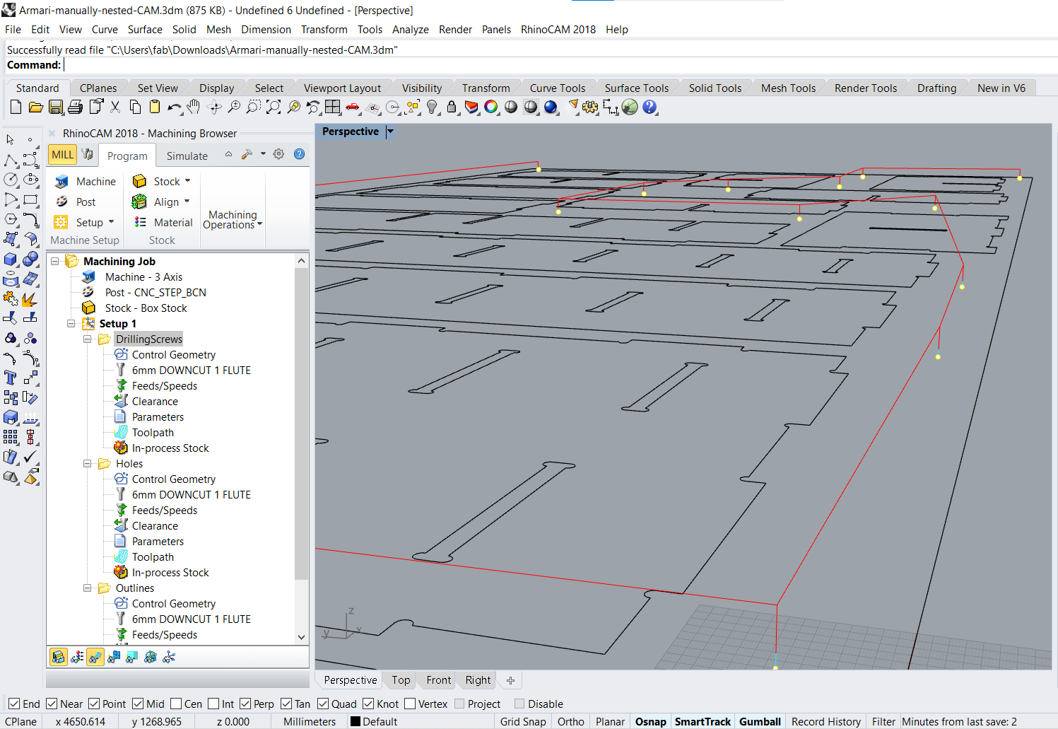
In our case, we will use the same tool for drilling and for cutting, so we just configured one tool (6mm)
Making pockets for fittings
The next step is to cut the out inner pockets
These pockets are cut first because they will not cause our stock material (or pieces of it) to move around or come off/fly away.

The important settings that we need to take into consideration while cutting pockets are:
- dogbones/tbones: which we already took care of during our design
- cut direction (climb/conventional): as it will affect our finishes on both sides of the material
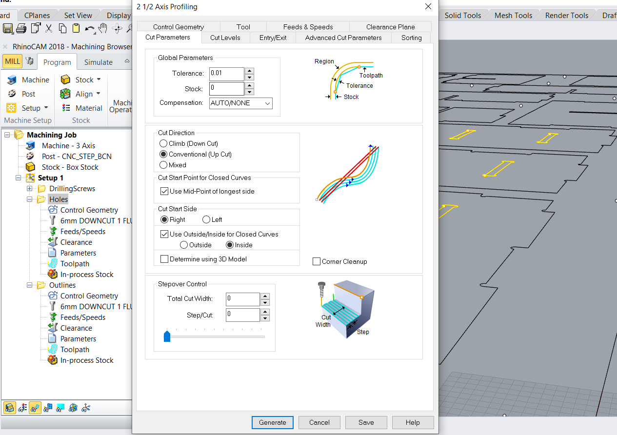
- feeds and speeds: which will determine your overall speed and time required to complete the job, as well as how much material you will remove for each rotation of your tool. These two dimensions are interlinked and generally will depend based on your endmill and your material’s hardness. The datasheet for your endmill should give you some basic numbers to get started.

- cut level and how many passes you’d like to do: this will depend on how thick your stock is, as you might have to do several passes at different depths. It’s better to be conservative with these values, as a too aggressive value might also cause your endmill to break.
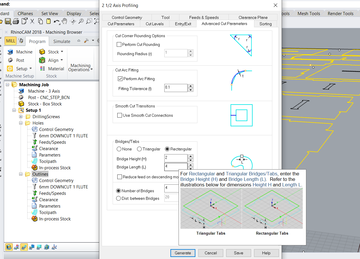
Cutting out the outline
This is the last operation you’ll want to do, as it will effectively leave the large pieces detached from the stock (or almost! detached).
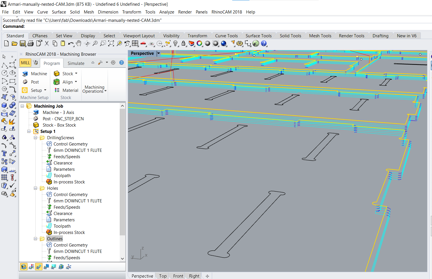
Even if you use tabs and bridges to make sure the pieces don’t fly off, you should still be careful and avoid performing any other operations on it. Bridges and tabs are relatively fragile and are there for convenience, they are not a safety measure since they are design to break away easily.
Milling
The milling process is a bit more complex than other fabrications because:
- we’re working with large pieces and
heavylarge masses - we’re working with large equipment that operate at fast speeds (both in rpm and in mm/s)
- we’re working with machines that do not have protective shields around them and move autonomously.
- we’re working with lots of energy (noise, flying debris, strong inertial forces)
This means that we must follow additional prevention steps and wear more protective equipment
Working safely 🛠⚠
- Check out the Group Documentation for a cheatsheet/breakdown of all steps
- Important reminders:
- Fix the large pieces of wood to the sacrificial board to ensure nothing comes flying off, and that it does not move during milling
- Wear all protective equipment (ears, eyes, ponytail, no rings, no bracelets, etc…)
- Do not operate the machine if you are
- If you are feeling H.A.L.T.D.ed = Hungry, Angry, Alone, Tired, Drunk,
- If you are in a Rush
- If you are on your own, without a peer helping/supervising/assisting
- Operate the machine with the right tooling (correct milling bits, and in correct maintenance status)
- Operate the machine with the correct speeds and feed rates. Use this online calculator to check your math. 🧮
Milling went fairly well and there were no surprises.
Here’s a short timelapse of the least boring bits.
Imagine this, but for more than 1h.
Assembling the pieces
Assembling the final shelves was, by far, the most arduous process.
Due to an mistake when adapting the design, I had to adjust all of the joint dimensions that were not dependent on the thickness of the material.
Mostly, the middle (long) parts of the dog-bones had to be shortened 0.2mm. That is: 54 different dimensions had to be adjusted manually.
This was because, when I parameterized the design, I configured it like so:
| Value | Feature |
|---|---|
| 9.05mm | thickness of material in real life (avg) |
| 9.05mm + 0.2mm | thickness of material in design |
| 100mm | length of dents for fitting at 90 degrees |
Then I should have done it like this:
| Value | Feature |
|---|---|
| 9.05mm | thickness of material in real life (avg) |
| 9.05mm | thickness of material in design |
| 100mm | length of dents for fitting at 90 degrees |
| + 0.2mm | milling adjustment |
| 9.05mm + 0.2mm | actual width for dog-bones |
| 100mm + 0.2mm | actual length for dog-bones |
| 100mm + 0.2mm | actual length of dents for fitting at 90 degrees |
This miscalculation resulted in me having to spend more than 4h filing all the edges to adjust them to the reality.
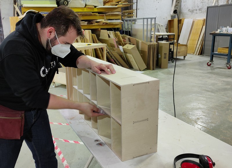
Imagine this, but for +4h. 😵
The alternative was to throw all this away and re-mill everything after adjusting the design.
I decided against it considering that it had a very simple solution (low complexity and low cognitive effort, but high time consumption), and the benefits would outweigh the costs: 100s of € and 2 sqm. lost in material (thrown away) when there’s a simple way to fix it would be a crime against nature.
Finished Product
As you can see the shelves fit into the main closet.
The left/top space gaps are there to accommodate the door hinges and the top hanger, that cannot be removed.
Lessons learned
Tolerances when designing for CNC Milling (Wood)
Add +0.2mm to all your fittings
Since the material gets slightly compressed during the milling process, we need to make the gaps a little larger than they should.
- This means that the gap sizes for fittings should be (thickness + 0.2mm), which I was quick to do.
Even for gaps that don’t depend on material thickness
- This also means that all the other fittings should be adjusted as well (so the teeth that join the backwall and the side panels should have been adjusted to be 10.2mm instead of just 10mm)
Unfortunately, I didn’t remember to do this, and I had to spend extra time sanding off these excess material manually after the pieces were milled.
Assets
Design files + RhinoCAM settings
NC files for CNC Miller
The files for the CNC had 4 parts, according to the order of the operations.