Electronics Programming
The core of our system is going to be the board that we designed and manufactured and its purpose will be to control all servos to eject the right coins at the right time, on command, and with precision.
If we have enough time, I will try to incorporate the coin acceptor signal so that the board can detect when new coins are inserted and then keep track of the status (how many coins are in the system, how many are inserted, how many are ejected, etc…)
Controlling Servos
The first thing we need to do is control servo movement so coins can be ejected.
If you remember from week 10 - output devices, it is not possible to import the Servo library and just use it out of the box. There is a missing bit in the translation layer between arduino IDE code and the underlying binary that will be flashed to the chip.
This means that we need to use the same strategy we used in the past: sending PWM pulses the hardcore way, using microsecond-precision timing.
Once again, we want to avoid reinventing the week, so a quick search finds us this working example from Devin Quinn, which claims to control SG90 using Atmel Atsamd D11D boards. This is exactly what we need.
In summary:
Ideally, it would be great to incorporate the Servo library for Arduino, but I could not get it to work, and I think the support is missing from the FabSam library, so the linked sample code above provides 2 advantages:
- It actually works
- It uses less resources
Controlling coin ejection through serial commands
void parsePcCommand(String command){
  if(command.equals("EJECT 010")){
    ejectCoin(EUR_010);
    Serial.println("10 cent coin ejected!");
  }else if(command.equals("EJECT 200")){
    ejectCoin(EUR_200);
    Serial.println("2 eur coin ejected!");
  }else{
    Serial.print("Unknown command:");
    Serial.println(command);
  }
}
Servo power needs - The need for stable power
PWM requires precise timing, and also has specific powering requirements…
Trying to run the servo at full speed, all the time results in power instability and the board losing power and resetting itself.
You can see the power LED turning off if we configure PWM pins to deliver pulses too fast (not waiting long enough for the servo to complete the movement and rest) consuming power constantly.
void servo_pwm(int pin, int dur){
  int LoopCount = 15;  // setting this lower than 25, will cause power instabilities

  for(i = 0; i < LoopCount; ++i){
    digitalWrite(pin, HIGH);
    delayMicroseconds(dur);
    digitalWrite(pin, LOW);
    delayMicroseconds(20000 - dur);
  }
}
This could be fixed by adding larger capacitors, or by changing the power delivery mechanism to provide full power to all servos (e.g. not using a single voltage regulator for all the servos), but since our application does not actually require concurrent servo usage, or long-running servo operations, this minor issue can be fixed in software, by just setting the servo activation function to wait a few milliseconds after the servo has finished moving, providing the system a much-needed rest.
Programming the board
The second (and slightly larger problem) that I came across when building this board was flashing it with custom code.
The toolchain for D11D is the same as for the D11C, except some things don’t seem to be in place. This resulted in problems when trying to flash it using the same method we used in the past (once with the programmer board, and then over USB).
This did not work, and I had to resort to always using the programmer board to flash custom programs. See cheatsheet for steps
The journey to programming the board
In hindsight, this was a useful learning experience, but the timing for board-programming issues could not have been worse.
The first board I picked was defective (which is something that never happens) and required 4 different instructors and a multitude of opinions and test to verify it. As soon as I replaced the board with a new one from the same reel, it all started working perfectly.
This video shows one of the issues, where the board “can” be programmed but cannot be verified (verification waits infinitely and never completes). The fact that it can be programmed does not mean that it actually worked. Write operations are opaque by nature and the only way to verify that things worked is to either explicitly read the content of the memory, or to see if the board works. Needless to say, the board did not work, so my suspicion is that it never actually got programmed properly.
The fact that this time-consuming problem:
- appeared at the worst possible time (debugging is an expensive task, especially when the problem is on the component that almost never fails)
- and it affected the most critical part of the project (the piece affected was at the core of the project and was responsible for its most critical feature: dispensing coins),
resulted in me wasting valuable time looking for problems in places that were working as expected.
The secret sauce
The sketch that controls the entire system is fairly simple.
It receives a commands from the user interface device (the laptop when programming it, or the touchscreen when the system is in use), and ejects the selected coin.
void parsePcCommand(String command){
  if(command.equals("EJECT 010")){
    ejectCoin(EUR_010);
  }else if(command.equals("EJECT 020")){
    ejectCoin(EUR_020);
  }else if(command.equals("EJECT 050")){
    ejectCoin(EUR_050);
  }else if(command.equals("EJECT 100")){
    ejectCoin(EUR_100);
  }else if(command.equals("EJECT 200")){
    ejectCoin(EUR_200);
  }else if(command.equals("EJECT EACH")){
    Serial.println("ejecting all coins, 1 at a time...");
    parsePcCommand("EJECT 200");
    parsePcCommand("EJECT 100");
    parsePcCommand("EJECT 050");
    parsePcCommand("EJECT 020");
    parsePcCommand("EJECT 010");
    Serial.println("all coins ejected!");
  }else{
    Serial.print("Unknown command:");
    Serial.println(command);
  }
}
The rest of the code is just a few utility methods and syntactic sugar to make the code a bit more readable.
In a future iteration, it would also receive coin acceptor inputs, and I’d like to make it a stateful system
A future vision - a stateful system
Right now the system is not wired to the coin acceptor component, so it cannot detect when a coin is inserted, nor the denomination of that coin. This was not completed just due to lack of time.
Ideally, once coin detection worked, I’d like to have the system detect coin types and then track the quantity of each coin type.
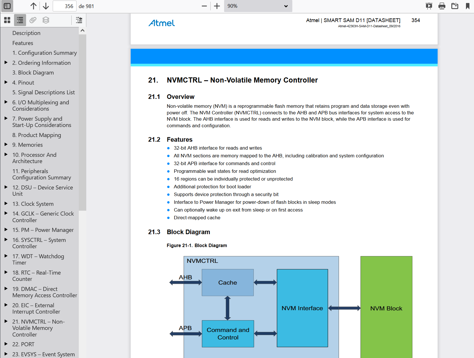
This could be made to survive system reboots by storing the state into the EEPROM, a small portion of the microcontroller’s non-volatile memory, that can be modified at runtime by the code running on the chip itself.
I do not know if the FabSam library supports this operation for this specific chip. It seems that mattairtech/ArduinoCore-samd includes supports for EEPROM_CAT25, a library that might be able to help:
Use Libraries Manager to install
EEPROM_CAT25 - Library for On Semiconductor CAT25 SPI EEPROM chips - Byte, block, and page transfers
Even with this, I do not have the certainty that this would work considering how little free memory there is after flashing a simple program. My concern is that adding more libraries might be too large for the limited memory size in this specific chip.
Cheatsheet - Workflow for flashing SAMD11D14AS
Unfortunately, the D11D board cannot be programmed via USB, and it requires a programmer board to upload the code.
These are the only 2 ways I have been able to upload code to it.
Simplified Workflow
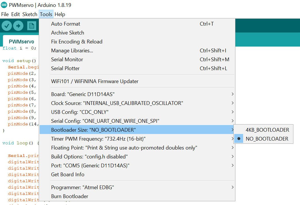
- Disable bootloader setting (No Bootloader 0Kb)
- If you skip this step, you will get compilation errors
- Upload using programmer
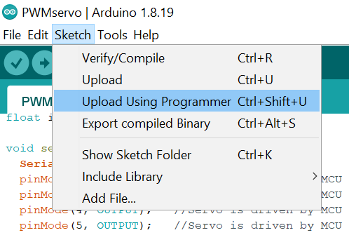
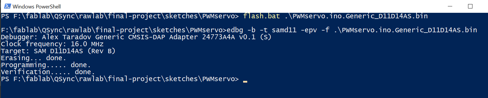
Workaround workflow
- Disable Bootloader
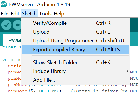
- Compile to external binary
- use EDBG to flash the .bin file
References
SAMD11D Pinout from mattairtech/ArduinoCore-samd
=====================================  ATsamD11D14AS  ===================================
Other COM   PWM  Analog  INT  Arduino*            Arduino*  Analog  INT  PWM   COM  Other
=========================================================================================
                                   1-------------------
            TCC01    *     *    5  | A5             A4 | 4    *     *   TCC00        REFB
     SS     TCC02    *          6  | A6             A3 | 3    *                      REFA
    MISO    TCC03    *     *    7  | A7             A2 | 2    *     *                 DAC
Xin32/Xin                       8  | A8 (XIN)      Vdd |
Xout32/Xout                     9  | A9 (XOUT)     Gnd |
  MOSI/TX2           *    NMI   14 | A14           A25 | 25                  USB D+
  SCK/RX2   TC11     *     *    15 | A15           A24 | 24                  USB D-
            TC10           *    16 | A16           A31 | 31         *   TC21  RX1   SWDIO
    SDA                    *    22 | A22           A30 | 30             TC20  TX1  SWDCLK
    SCL                         23 | A23       RST/A28 | 28                          BOOT
============================================================================================================================================
Arduino | Port  | Alternate Function    | Comments (! means not used with this peripheral assignment)
--------|-------|-----------------------|-------------------------------------------------------------------------------------------
0   | ----  | NOT A PIN     | NOT A PIN
1   | ----  | NOT A PIN     | NOT A PIN
2   | PA02  | DAC           | EIC/EXTINT[2] ADC/AIN[0] PTC/Y[0] DAC/VOUT
3   | PA03  | REFA          | !EIC/EXTINT[3] REF/ADC/VREFA REF/DAC/VREFA ADC/AIN[1] PTC/Y[1]
4   | PA04  | REFB / TCC00      | EIC/EXTINT[4] REF/ADC/VREFB ADC/AIN[4] AC/AIN[0] PTC/Y[2] !SERCOM0/PAD[2] !SERCOM0/PAD[0] !TC1/WO[0] TCC0/WO[0]
5   | PA05  | TCC01         | EIC/EXTINT[5] ADC/AIN[3] AC/AIN[1] PTC/Y[3] !SERCOM0/PAD[3] !SERCOM0/PAD[1] !TC1/WO[1] TCC0/WO[1]
6   | PA06  | SS (unused) / TCC02   | !EIC/EXTINT[6] ADC/AIN[4] AC/AIN[2] PTC/Y[4] SERCOM0/PAD[0] !SERCOM0/PAD[2] !TC2/WO[0] TCC0/WO[2]
7   | PA07  | MISO / TCC03      | EIC/EXTINT[7] ADC/AIN[5] AC/AIN[3] PTC/Y[5] SERCOM0/PAD[1] !SERCOM0/PAD[3] !TC2/WO[1] TCC0/WO[3]
8   | PA08  | Xin32 / Xin       | Xin32
9   | PA09  | Xout32 / Xout     | Xout32
10  | ----  | NOT A PIN             | NOT A PIN
11  | ----  | NOT A PIN             | NOT A PIN
12  | ----  | NOT A PIN     | NOT A PIN
13  | ----  | NOT A PIN     | NOT A PIN
14  | PA14  | MOSI / TX2            | EIC/NMI ADC/AIN[6] PTC/X[0] PTC/Y[6] SERCOM0/PAD[0] !SERCOM2/PAD[0] !TC1/WO[0] !TCC0/WO[0]
15  | PA15  | SCK / RX2 / TC11      | EIC/EXTINT[1] ADC/AIN[7] PTC/X[1] PTC/Y[7] SERCOM0/PAD[1] !SERCOM2/PAD[1] TC1/WO[1] !TCC0/WO[1]
16  | PA16  | TC10          | EIC/EXTINT[0] PTC/X[4] PTC/Y[10] !SERCOM1/PAD[2] !SERCOM2/PAD[2] TC1/WO[0] !TCC0/WO[6]
17  | ----  | NOT A PIN             | NOT A PIN
18  | ----  | NOT A PIN     | NOT A PIN
19  | ----  | NOT A PIN     | NOT A PIN
20  | ----  | NOT A PIN     | NOT A PIN
21  | ----  | NOT A PIN     | NOT A PIN
22  | PA22  | SDA               | EIC/EXTINT[6] PTC/X[6] PTC/Y[12] !SERCOM1/PAD[0] SERCOM2/PAD[0] !TC1/WO[0] !TCC0/WO[4]
23  | PA23  | SCL                   | !EIC/EXTINT[7] PTC/X[7] PTC/Y[13] !SERCOM1/PAD[1] SERCOM2/PAD[1] !TC1/WO[1] !TCC0/WO[5]
24  | PA24  | USB_NEGATIVE      | USB/DM
25  | PA25  | USB_POSITIVE      | USB/DP
26  | ----  | NOT A PIN     | NOT A PIN
27  | ----  | NOT A PIN             | NOT A PIN
28  | PA28  | Reset         | Reset, BOOT (double tap bootloader entry)
29  | ----  | NOT A PIN     | NOT A PIN
30  | PA30  | TX1 / TC20 / SWD CLK  | !EIC/EXTINT[2] !SERCOM1/PAD[0] SERCOM1/PAD[2] TC2/WO[0] !TCC0/WO[2] SWD CLK, leave floating during boot
31  | PA31  | RX1 / TC21 / SWD IO   | EIC/EXTINT[3] !SERCOM1/PAD[1] SERCOM1/PAD[3] TC2/WO[1] !TCC0/WO[3] SWD IO
========================================================================================================================