Output Devices

A Stepper motor - one of the most common actuators
This week’s project
This week I wanted to build a small metronome using a servo motor (for the movement) and maybe a buzzer (for the sound), if I had time to do a second iteration.

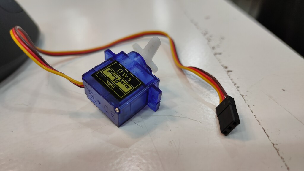
The servo motor that was available in my lab was the Micro SG90, very common and inexpensive servo in a compact micro size package.
MOSFET basics for this week
This week I am going to need a MOSFET to control the servo, so I have spent a bit of time to learn more about MOSFETs, how they work, and how to use them
Spoiler alert: I did not need MOSFETs in the end because:
- The lab ran out of MOSFETs
- and I actually didn’t really need them because the servo could be driven using the 3v3 output from the SAMD11C
Equipment I plan on using
Motor - Features
- Brown = Ground ( pin 1)
- Red = 5V (pin 2)
- Orange = PWM Signal (pin3)
The servo runs on 5V with a current draw about 10mA at idle and 100mA to 250mA
Speaker / Buzzer
The buzzer can be used to make a clicky sounds, although the sound it makes is very quiet (at least during the MVP phase)
Features
- Positive Pole = 5V
- Negative = GND
Auto-routing with LayoutEditor
This week I wanted to explore using an automated application to calculate the position for the traces on the board. The hope is that it will save me quite a bit of time this week (and in future weeks).
Most tutorials that show how to use a computer to do Auto-routing of traces talk about this piece of software: Layout Editor. It can be downloaded for free from its official download page

Since I will be using this regularly, I want to make a shortcut for easier access.
We can use the process monitor in Linux to find out the path of the binary for any running process.
Let’s find out where is our installed App!
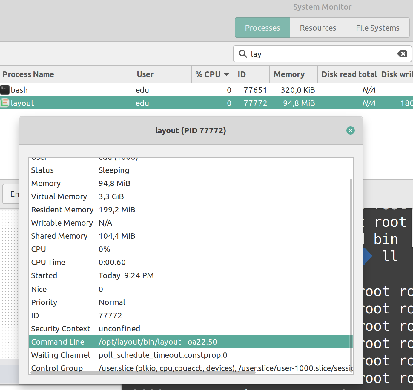
LayoutEditor is a fully featured suite to design Integrated Circuits and boards, but we are not going to use it; we are only interested in using a specific tool inside the suite called FreeRouting.
FreeRouting is a java application packaged as an executable JAR file, which means it can run on any system that has the Java Runtime installed.
If we run Free Routing from that folder

If you have linux mint/ubuntu, you can create a new launcher (a.k.a. desktop shortcut) to the app with this command:
java -jar /opt/layout/bin/freeRouting.jar
Once you launch the application, you will be asked to select the DSN file that you just exported from KiCad.
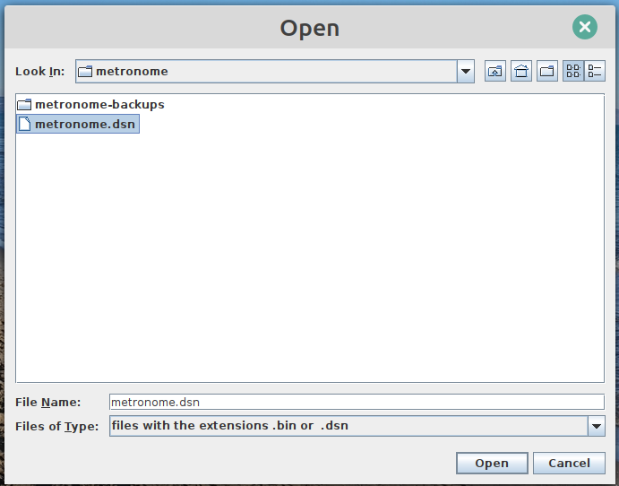
We can validate that the file is loaded correctly
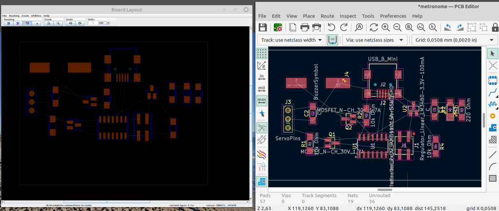
Important settings to change:
- Disable layer B.Cu (the back layer should not be considered when auto-routing the traces, because our boards only have 1 side)
- Optional: Disable “vias allowed” (although it will have no effect on boards that only have 1 side)

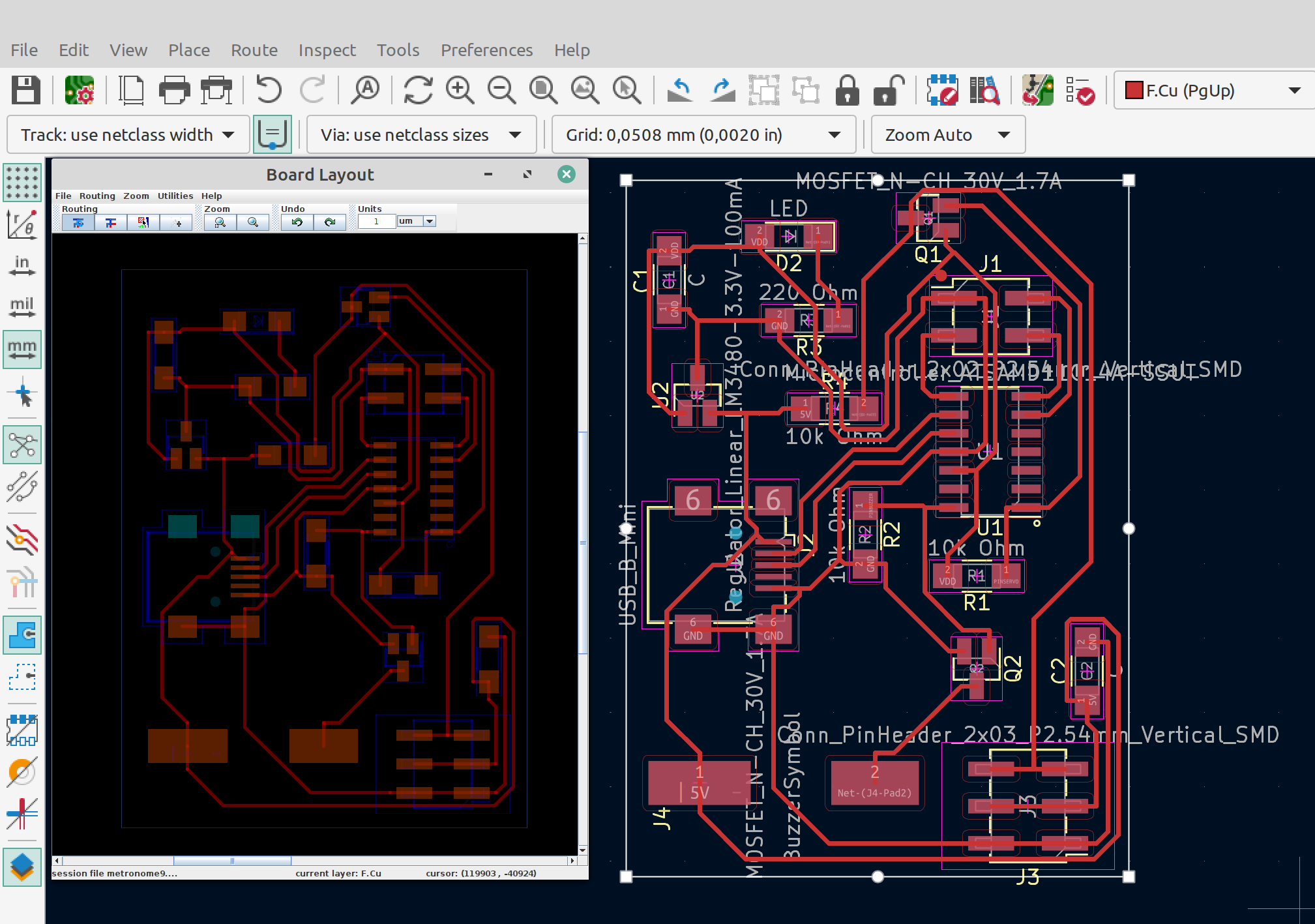
Kicad Sketch

Problems
Device is not recognized even after flashing bootloader
The first iteration resulted in unexpected behaviour (unsurprisingly!)
The good news is that I was one step ahead, and I had actually milled and soldered 2 identical boards (learn by doing, multiple times!)
[  320.951501] usb 1-1: USB disconnect, device number 7
[  346.493001] usb 3-1.2: new low-speed USB device number 8 using xhci_hcd
[  346.636778] usb 3-1.2: device descriptor read/64, error -32
[  346.877024] usb 3-1.2: device descriptor read/64, error -32
[  347.120815] usb 3-1.2: new low-speed USB device number 9 using xhci_hcd
[  347.252951] usb 3-1.2: device descriptor read/64, error -32
[  347.493139] usb 3-1.2: device descriptor read/64, error -32
[  347.601335] usb 3-1-port2: attempt power cycle
[  355.373045] usb 3-1.2: new low-speed USB device number 11 using xhci_hcd
[  355.504845] usb 3-1.2: device descriptor read/64, error -32
[  355.744909] usb 3-1.2: device descriptor read/64, error -32
[  355.981017] usb 3-1.2: new low-speed USB device number 12 using xhci_hcd
[  356.113188] usb 3-1.2: device descriptor read/64, error -32
[  356.353067] usb 3-1.2: device descriptor read/64, error -32
[  356.461049] usb 3-1-port2: attempt power cycle
The second board
This is the output when I tried to plug in the second copy of the first design I created.
You, a smart, cute and sweet reader, will easily spot the similarities with the previous board.
[ 2634.877066] usb 1-2: new full-speed USB device number 9 using xhci_hcd
[ 2640.069467] usb 1-2: unable to read config index 0 descriptor/all
[ 2640.069480] usb 1-2: can't read configurations, error -110
[ 2640.197464] usb 1-2: new full-speed USB device number 10 using xhci_hcd
[ 2655.817459] usb 1-2: device descriptor read/64, error -110
[  117.991831] usb 3-2.2: new full-speed USB device number 5 using xhci_hcd
[  138.549195] usb 3-2.2: New USB device found, idVendor=16d0, idProduct=0557, bcdDevice= 2.00
[  138.549207] usb 3-2.2: New USB device strings: Mfr=1, Product=2, SerialNumber=0
[  143.678733] usb 3-2.2: can't set config #1, error -110
Alright… the problem is so consistent that this helps us narrow down the issue. By now it is pretty clear that it’s not:
- An issue with a specific component
- An issue with the soldering of one of the boards
- An issue with some accidental oversight
It had to be something wrong with BOTH boards (the most expensive way to troubleshoot 😅)
This page seems to indicate that error 110 could be a Timeout errors
[  605.297657] EXT4-fs (nvme0n1p9): mounted filesystem with ordered data mode. Opts: (null). Quota mode: none.
[  616.687830] usb 1-1: new full-speed USB device number 7 using xhci_hcd
[  621.963960] usb 1-1: unable to read config index 0 descriptor/all
[  621.963966] usb 1-1: can't read configurations, error -110
[  622.092299] usb 1-1: new full-speed USB device number 8 using xhci_hcd
[  637.708398] usb 1-1: device descriptor read/64, error -110
It seems to match, because there are some consistencies (a 15 sec timeout)
If we go back to the datasheet of the processor, it does not mention anything related to this potential error message or code. There are 56 matches for “110” but all of them are either page references or sample hex memory addresses for power management.
While trying to upload my program via SWD, it also fails. The other funny thing is that, as soon as it crashes the system ejects both boards:
- the programmers (it stops appearing when we run
edbg -l) - and the target (
Error opening serial port '/dev/ttyACM1')
This is a detailed log:
   text    data     bss     dec     hex filename
  10256       0    1768   12024    2ef8 /tmp/arduino_build_772050/sketch_apr05a.ino.elf
/home/edu/.arduino15/packages/arduino/tools/arm-none-eabi-gcc/4.8.3-2014q1/bin/arm-none-eabi-size -A /tmp/arduino_build_772050/sketch_apr05a.ino.elf
Sketch uses 9888 bytes (60%) of program storage space. Maximum is 16384 bytes.
/home/edu/.arduino15/packages/arduino/tools/openocd/0.9.0-arduino/bin/openocd -d2 -s /home/edu/.arduino15/packages/arduino/tools/openocd/0.9.0-arduino/share/openocd/scripts/ -f /home/edu/.arduino15/packages/Fab_SAM_Arduino/hardware/samd/1.6.18-alpha2/variants/Generic_D11C14A/openocd_scripts/SAMD11C14A.cfg -c telnet_port disabled; program {{/tmp/arduino_build_772050/sketch_apr05a.ino.elf}} verify reset; shutdown
Open On-Chip Debugger 0.9.0-gd4b7679 (2014-10-03-00:26)
Licensed under GNU GPL v2
For bug reports, read
    http://openocd.org/doc/doxygen/bugs.html
debug_level: 2
Info : only one transport option; autoselect 'swd'
adapter speed: 500 kHz
adapter_nsrst_delay: 100
cortex_m reset_config sysresetreq
Info : CMSIS-DAP: SWD  Supported
Info : CMSIS-DAP: Interface Initialised (SWD)
Info : CMSIS-DAP: FW Version = v0.1
Info : SWCLK/TCK = 1 SWDIO/TMS = 1 TDI = 0 TDO = 0 nTRST = 0 nRESET = 1
Info : CMSIS-DAP: Interface ready
Info : clock speed 500 kHz
in procedure 'program'
in procedure 'init' called at file "embedded:startup.tcl", line 473
in procedure 'ocd_bouncer'
** OpenOCD init failed **
shutdown command invoked

An error occurred while uploading the sketch
processing.app.SerialException: Error opening serial port '/dev/ttyACM1'.
    at processing.app.Serial.<init>(Serial.java:152)
    at processing.app.Serial.<init>(Serial.java:82)
    at processing.app.SerialMonitor$2.<init>(SerialMonitor.java:132)
    at processing.app.SerialMonitor.open(SerialMonitor.java:132)
    at processing.app.AbstractMonitor.resume(AbstractMonitor.java:132)
    at processing.app.Editor.resumeOrCloseSerialMonitor(Editor.java:2126)
    at processing.app.Editor.access$1300(Editor.java:116)
    at processing.app.Editor$UploadHandler.run(Editor.java:2095)
    at java.lang.Thread.run(Thread.java:748)
Caused by: jssc.SerialPortException: Port name - /dev/ttyACM1; Method name - openPort(); Exception type - Port not found.
    at jssc.SerialPort.openPort(SerialPort.java:167)
    at processing.app.Serial.<init>(Serial.java:141)
    ... 8 more
Error opening serial port '/dev/ttyACM1'.
The behaviour is flaky at best and even in the cases where it works, I only managed to connect to the target board for 4 seconds (to get 2 messages via serial) before the connection was lost.

Second Attempt
This second attempt was a minor redesign of the board that will not have the 5V trace going RIGHT BELOW the case for the mini-USB port. The reason for this change in design is that the outer case for the USB port is always connected to GND and the hypothesis, at the time, was that the inconsistencies and erratic behaviour was caused by tiny shorts between 5V and GND, which could make the PC disconnect the USB to avoid dangers.
That seemed to be the only smelly thing in the original design, so it made sense. Since it was consistent on both boards, it had a high probability to be the culprit.

Unfortunately, this did not seem to fix the issue, so the original root cause of the problem was still there (or partially there).
00000312 T USBDeviceClass::initEP(unsigned long, unsigned long)
00000332 T pinPeripheral
00000348 T USBDeviceClass::ISRHandler()
00000356 W DoubleBufferedEPOutHandler::_recv()
00000384 T g_APinDescription
00000420 T tone(unsigned long, unsigned long, unsigned long)
00000448 b udd_ep_in_cache_buffer
00000448 b udd_ep_out_cache_buffer
/home/edu/.arduino15/packages/arduino/tools/arm-none-eabi-gcc/4.8.3-2014q1/bin/arm-none-eabi-size -B /tmp/arduino_build_17143/sketch_apr05a.ino.elf
text       data     bss     dec     hex filename
10288         0    1788   12076    2f2c /tmp/arduino_build_17143/sketch_apr05a.ino.elf
/home/edu/.arduino15/packages/arduino/tools/arm-none-eabi-gcc/4.8.3-2014q1/bin/arm-none-eabi-size -A /tmp/arduino_build_17143/sketch_apr05a.ino.elf
Sketch uses 9920 bytes (60%) of program storage space. Maximum is 16384 bytes.
/home/edu/.arduino15/packages/arduino/tools/openocd/0.9.0-arduino/bin/openocd -d2 -s /home/edu/.arduino15/packages/arduino/tools/openocd/0.9.0-arduino/share/openocd/scripts/ -f /home/edu/.arduino15/packages/Fab_SAM_Arduino/hardware/samd/1.6.18-alpha2/variants/Generic_D11C14A/openocd_scripts/SAMD11C14A.cfg -c telnet_port disabled; program {{/tmp/arduino_build_17143/sketch_apr05a.ino.elf}} verify reset; shutdown
Open On-Chip Debugger 0.9.0-gd4b7679 (2014-10-03-00:26)
Licensed under GNU GPL v2
For bug reports, read
http://openocd.org/doc/doxygen/bugs.html
debug_level: 2
Info : only one transport option; autoselect 'swd'
adapter speed: 500 kHz
adapter_nsrst_delay: 100
cortex_m reset_config sysresetreq
Error: unable to find CMSIS-DAP device
Error: No Valid JTAG Interface Configured.
Error: No Valid JTAG Interface Configured.
While uploading normally (via usb without programmer)
Uploading using selected port: /dev/ttyACM0
/home/edu/.arduino15/packages/Fab_SAM_Arduino/tools/bossac/1.7.0-mattairtech-3/bossac -i -d --port=ttyACM0 -U true -i -e -w -v /tmp/arduino_build_17143/sketch_apr05a.ino.bin -R
No device found on ttyACM0
Set binary mode
readWord(addr=0)=0x20000ffc
Send auto-baud
Set binary mode
readWord(addr=0)=0x20000ffc
An error occurred while uploading the sketch
After attempting to re-solder all solder points, the board is recognized as USB, but when we try to flash our custom program, it stops working.
[ 2066.034917] usb 3-2.2: device descriptor read/64, error -32
[ 2066.246938] usb 3-2.2: device descriptor read/64, error -32
[ 2066.458697] usb 3-2.2: new full-speed USB device number 9 using xhci_hcd
[ 2066.562810] usb 3-2.2: device descriptor read/64, error -32
[ 2066.774800] usb 3-2.2: device descriptor read/64, error -32
[ 2066.882759] usb 3-2-port2: attempt power cycle
[ 2067.534549] usb 3-2.2: new full-speed USB device number 10 using xhci_hcd
[ 2067.534683] usb 3-2.2: Device not responding to setup address.
[ 2067.742625] usb 3-2.2: Device not responding to setup address.
[ 2067.950484] usb 3-2.2: device not accepting address 10, error -71
[ 2068.058464] usb 3-2.2: new full-speed USB device number 11 using xhci_hcd
[ 2068.058569] usb 3-2.2: Device not responding to setup address.
[ 2068.266813] usb 3-2.2: Device not responding to setup address.
[ 2068.474471] usb 3-2.2: device not accepting address 11, error -71
[ 2068.474755] usb 3-2-port2: unable to enumerate USB device
If we try to program the bootloader again, it fails.
If we try to flash our code without bootloader via JTAG, it also fails
Sketch uses 9920 bytes (60%) of program storage space. Maximum is 16384 bytes.
/home/edu/.arduino15/packages/arduino/tools/openocd/0.9.0-arduino/bin/openocd -d2 -s /home/edu/.arduino15/packages/arduino/tools/openocd/0.9.0-arduino/share/openocd/scripts/ -f /home/edu/.arduino15/packages/Fab_SAM_Arduino/hardware/samd/1.6.18-alpha2/variants/Generic_D11C14A/openocd_scripts/SAMD11C14A.cfg -c telnet_port disabled; program {{/tmp/arduino_build_815326/sketch_apr05a.ino.elf}} verify reset; shutdown
Open On-Chip Debugger 0.9.0-gd4b7679 (2014-10-03-00:26)
Licensed under GNU GPL v2
For bug reports, read
    http://openocd.org/doc/doxygen/bugs.html
debug_level: 2
Info : only one transport option; autoselect 'swd'
adapter speed: 500 kHz
adapter_nsrst_delay: 100
cortex_m reset_config sysresetreq
Error: unable to find CMSIS-DAP device
Error: No Valid JTAG Interface Configured.
Error: No Valid JTAG Interface Configured.
The Root cause
Alright, so up until now, we have learned that:
- There is a problem with the first board I designed.
- Even after milling and soldering 2 copies of that same board, the problem persisted.
- The problem is not a once-off and is probably systemic due to something I forgot
- Removing the 5V trace away from GND did not fix it either
- Whatever it is, it’s unlikely to go away by doing a 3rd board.
- After asking for assistance to the lab lecturers (god bless them!) and being as confused as I was, I was advised to do
a 3rd board anyway as a way to retrace the steps.
- Sometimes the counter-intuitive thing, actually works and helps us remember the steps we took in the past.
So, what was the problem?
I came across the root cause as I was preparing to mill and solder a 4th board, and I was collecting the components from the electronics Inventory system.
A suddent flashback reminded me that I took the capacitors from the “1000 pF capacitor” bin (= 1 nF) instead of using the “1 µF” bin! This is a 1000x smaller than needed.
My guess is that it was not large enough to provide stable voltage for the microcontroller.
Sure enough, once I removed the 1 nF capacitors from all the boards, and replaced them with the right capacity ones (1 µF), all the boards started working correctly.
A new problem appears
Just when I thought I finished fixing all the issues with that board, a new challenge appeared.
When we tried to use this sample code for servos on Arduino, I get errors saying that the library I’m trying to use (Servo library for Arduino) is not compatible with FabSam library/translation layer for SAMD11xxxx
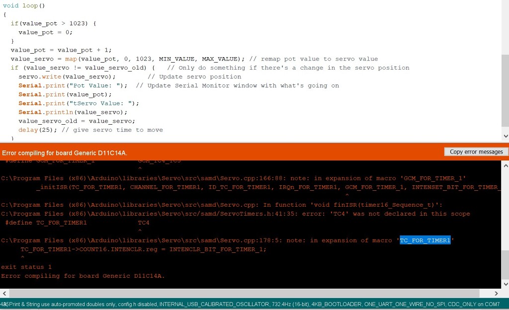
After some quick googling, it seems to be a known issue for SAMD . ISSUE #21 “Incomplete samd51 implementation” (in repo arduino-libraries/Servo)
This sheds some additional light into the issue:
https://github.com/arduino-libraries/Servo/blob/master/src/samd/ServoTimers.h#L37 ( as of today: Latest commit 6f710d6 on 11 Apr 2021 )
/**
 * SAMD Only definitions
 * ---------------------
 */

// For SAMD:
#define _useTimer1
//#define _useTimer2   // <- TODO do not activate until the code in Servo.cpp has been changed in order
        //         to manage more than one channel per timer on the SAMD architecture

        #if defined(_useTimer1)
        #define TC_FOR_TIMER1 TC4
        #define CHANNEL_FOR_TIMER1 0
Seeing that the Servo library will not work for us, we will have to implement PWM manually, like real developers.
The SG90 servo requires HIGH pulses of metween 1ms and 2ms. The duration of the signal expresses the angular position of the servo.
This simple function will send pulses out through the specified pin, for the specified duration of time.
I found that 35 repetitions is enough time for the servo to fully move to the final position. Anything below 25 was not enough time to complete the full travel, so 35 is a safe enough number that guarantees movement completion before returning control to the caller.
void servo_pwm(int pin, int dur){
  int LoopCount = 35;

  for(i = 0; i < LoopCount; ++i){
    digitalWrite(pin, HIGH);
    delayMicroseconds(dur);
    digitalWrite(pin, LOW);
    delayMicroseconds(20000 - dur);
  }
}
The working board
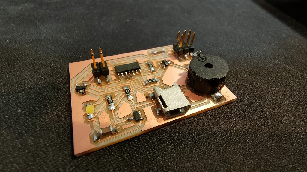
In this video you can see the servo repeatedly moving back and forth to mimic the movement of the metronome.
Tips and Tricks
Updating footprints in KiCad - Linux Mint
Sometimes you need to update footprint files, but the files are only writable by root.
If you are having permission issues/errors while updating the footprints in kicad, this command will set all files as
writable for all users. As with all commands that use sudo, watch out and make sure you understand what this does
before you run it.
cd /usr/share/kicad/footprints
sudo find . -type f -iname "*.kicad_mod" -exec chmod a+w {} \;
The reason why we had to do this, this week, is that we needed custom footprints for the buzzer.
During week 12 I created a detailed cheatsheet on creating custom footprints in KiCad , which includes all the lessons learned during weeks 10, 11 and 12.
Errors while exporting DSN file for auto-routing
If you see this error message while trying to export your DSN, just go to the menu Inspect -> Design Rule Checker
Error message: “Board outline is malformed. Run DRC for a full analysis.”
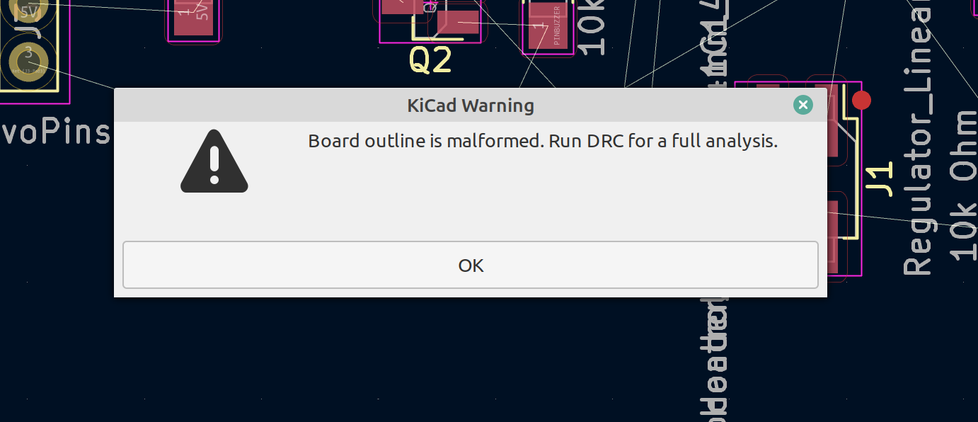
You will see a summary of all the problems that it detected.

If you look closely, all the issues are:
- 36 unconnected traces
- that’s ok! because we are exporting a DSN file to do the routing)
- 1 error of “board has malformed outline”
- this one, we can easily fix by:
- selecting the
Edge.cutslayer as active - adding our outline using
Place->Draw Rectangle
- selecting the
- this one, we can easily fix by:
- 3 Warnings about silkscreen overlap
- that we will bravely ignore until it’s too late.
- but that these will have no impact because we’re valiant fabricators, and we make our own boards, without silkscreens! ✌😎
Once these errors are fixed, we’re good to continue.

Even though the error appeared, we can still use the file that was just exported.
This trick allows us to:
- Build boards much faster
- Avoid boring work
- Get fast feedback on the positions of our components.
- We can just run auto-routing, and if we see that the program struggles too much, we just position the elements with a bit more separation
- Ultimately, fit x2 the amount of boards in the same space as when we did the routing manually, saving material and time.

Avoid traces under the USB port
Traces under the USB port can cause shorts. Below you can find a video showing me checking a few connectivity pairings:
- ✅ 🙂 testing continuity on a large pad (to make sure my multimeter works properly)
- ✅ 🙂 testing continuity on the 5V trace that goes below the USB port (works, as expected)
- ✅ 😢 testing continuity between the 5V trace that goes underneath the USB port and the GND on the outside port shield (works, but it shouldn’t have)
This did not happen on the first board, but it immediately occurred on my second board.
Closing thoughts on learning vs performing
The original plan for this week was to create an extensible board that I could reuse over the next few weeks in the different projects and assignments.
However, after weighing in the pros and cons, I decided to go in the exact opposite direction, and keep making 1 new board each week.
➡ The fundamental reason for this decision is that this course is supposed to be a learning environment, not a performing environment .
If this course was about performing, it would make sense to optimize and design components for extensibility, but this is not what FabAcademy is like (despite the weekly show & tells, the local streaming events and the rest of ceremonies that accompany us).
FabAcademy is meant to be a learning environment, and sometimes we might forget it, making us rush to “perform and impress”, which is counterproductive to our long term learning. If you hack it for a week, but you don’t actually learn the key skills, no one will actually care, and you will be worse off than if you had.
Group Project
Assets
- 🆕 fab_with_buzzer.kicad_sym.zip The fab library expanded with footprints for a buzzer (required if you want to view/edit the kicad files)
- metronome-outline.png The outline image
- metronome-traces.png The traces image
- metronome-outline.rml The outline cutting program
- metronome-traces.rml The traces milling program
- metronome9-done.dsn The DSN file that AutoRouting created for our board
- metronome1.ino The Arduino Sketch file that controls the servo, its frequency and position.
- metronome2.zip The KiCad Design files for the board.