Embedded Programming
Individual assignment
- read the data sheet for your microcontroller ✅
- use your programmer to program your board to do something ✅
- extra credit: try other programming languages and development environments ✅
The outcome
Turn on the LED when the button gets pressed
Turn on the LED when the button does not get pressed
Make the LED blink 5 times whenever the button gets pressed
Soldering the board (again)
So, I spent most of this week practicing soldering (again).
➡ For Reference: Read more about my suffering when soldering.
If you’ve kept up with my doc, you already know that I hate soldering as much as soldering hates me.
This week I had to solder the board, and then re-solder it 4 more times.
It ended up being better for my mental health to rebrand this week as “Electronics Production - Part 2 with a bit of programming on Wednesday morning” than to consider it a programming week.
If figured out programming would be the easier part and, comparing to soldering, it was!
Measuring the suffering, by type, using the Schulz Scale
Allow me to present the raw data for your evaluation:
| Suffering Units | Soldering the board ⭐⭐ | Programming the board ⭐⭐⭐⭐⭐ | |
|---|---|---|---|
| Number of fingers burned | 🔨 physical suffering unit | 1 P unit | 0 P unit |
| Number of mental breakdowns | 🤯 psychological suffering unit | 7 PS units | 2 or 3 PS units (= standard in any programming endeavour) |
| Number of times I summoned Satan | ☔ existential suffering unit | 2 E units | 0 E units |
| Number of times I summoned Satan out loud in the lab | ☔ existential suffering unit | 1 E units | 0 E units |
| Number of times I reattempted the job from scratch | 🤯 psychological suffering unit | 4 PS units | 1 PS units |
These values have been normalized across the “Suffering Scales” , Schulz et al. (2010)
Legend:
| Unit | Description |
|---|---|
| P | physical suffering unit |
| PS | psychological suffering unit |
| E | existential suffering unit |
Summary: Programming caused the least suffering from the two activities, by far.
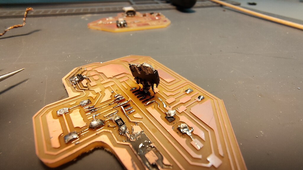
Seeing the finished board(s)
This week was about crossing the mental barrier around soldering, and finding ways to stop hating it, so I decided to mill extra boards and spend some quality time getting to know my enemy.

Flashing the board with a bootloader
Once I had a board that worked properly, flashing it with a bootloader was relatively easy, fast and pain-free.
Lol… no it wasn’t. Are you even reading this?! Please pay attention.
The first issue I encountered was that my meta-programmer board was “good enough” to be flashed with a bootloader (done 2 weeks ago), but was not soldered well enough to be able to program other boards. One of the jumpers was loose.
After a few soldering-iron smacks, it started to behave as expected, and then it was able to program the target boards.
🤚 I will use the singular term “board” from now on, but most of the operations I am describing in this week’s doc were performed and tested multiple times on multiple iterations of the board (some boards were “better” soldered, some were more “artistically” soldered)
Installing EDBG on Linux
Clone source from github.com using git clone https://github.com/ataradov/edbg.git
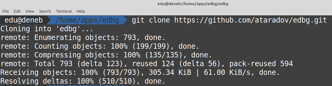
and then build the binaries from source


As sugar, you can move the edbg executable to /usr/local/bin/edbg and give it executable permissions, so it’s
available from anywhere in the system.
EDBG will allow you to flash firmware into your target board, via a meta-programmer plugged into your USB port.
Flashing the specific bootloader for your board.
Now that we have edbg installed and working, we can download the firmware for the D11C board:
The bin file that we are looking for is called sam_ba_SAMD11C14A.bin , and I also stored a backup of it in my repo for archival purposes.
The last thing we need to do is run this command to flash the bootloader we just downloaded into our target board.
edbg -ebpv -t samd11 -f sam_ba_SAMD11C14A.bin
The Flashing process
The first step to flash a custom bootloader/firmware unto a blank microprocessor is using an application like EDBG.

Here’s the output of programming the target board (SAM D11C) using my meta-programmer board that I built 4 weeks ago.
As you can see, the correct way to connect the boards is:
- Laptop to meta programmer via USB port for power and data.
- Laptop to target board via USB port for power only.
- meta programmer output pins to target board input pins via 4 cable ribbon.
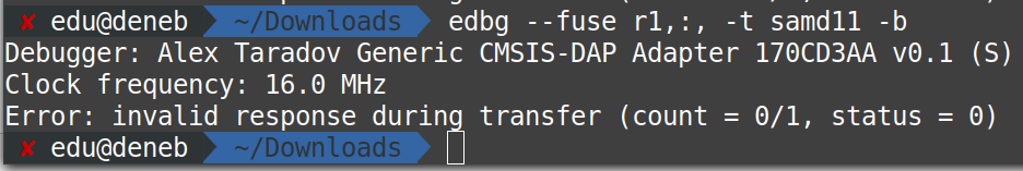
Problems during flashing
Something we can do to check if our board is working properly is try to read its internal fuses
The command below will attempt to read them and report any success/problems.
edbg --fuse r1,:, -t samd11 -b
The first time we tried to do this, the board was not soldered properly, so this is what the output looked like:
Programming the board with custom software
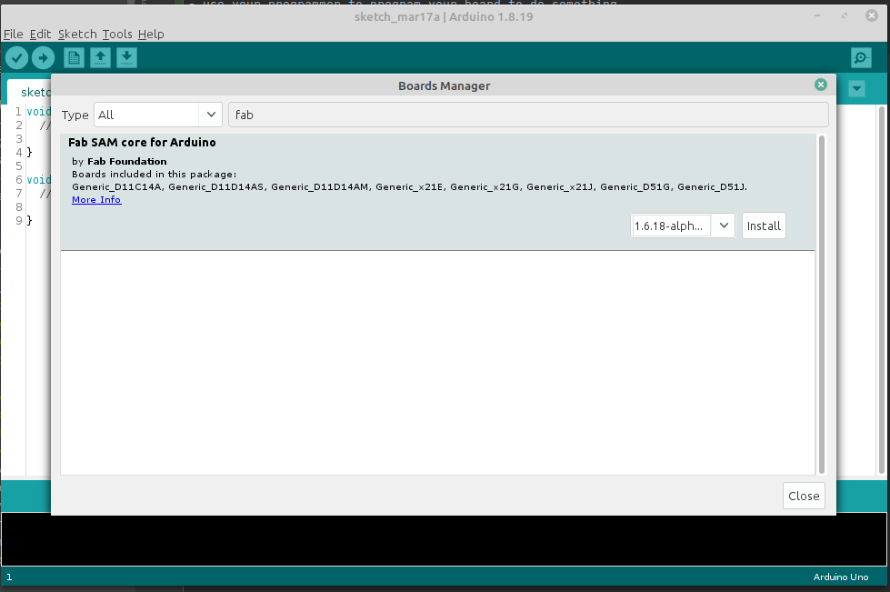
Configuring Arduino IDE
The first step is configuring Arduino IDE to support SAMD11C by installing the FamSAM Core for Arduino
Add new source:
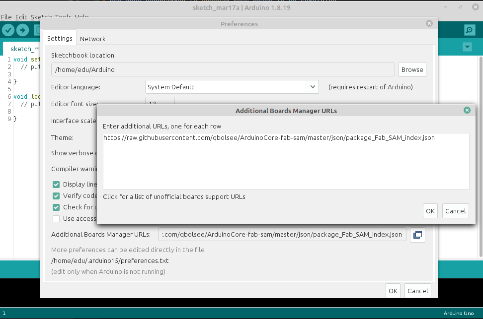
Add new Board Managers from FabSAM:
You can enter this url:
https://raw.githubusercontent.com/qbolsee/ArduinoCore-fab-sam/master/json/package_Fab_SAM_index.json
In addition, here’s a backup / snapshot as of Mar 2022
Once this source is configured, you can install the FabSAM Core for Arduino using the Boards Manager:

The Datasheet
Arguably, one of the most important things we should do before starting to design a new board, is to pick a microprocessor that’s up to the specs we need (speed, memory, pins, capabilities, etc…)
The best way to figure out what we’d need is to check out their datasheets and find out their capabilities.
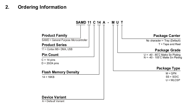
If you’ve ever wondered why this microcontroller would have such a cryptic and obscure name, I have news for you: this is what you get when your product is named by engineers without supervision. Still, it’s better than when products are named by Marketing people.
Datasheet reference
See the original datasheet from microchip.com.
SAM D11C pin-out configuration
The next thing we need to know (both, during design and also during programming) is, which pins we are going to use to interact with the outside world.
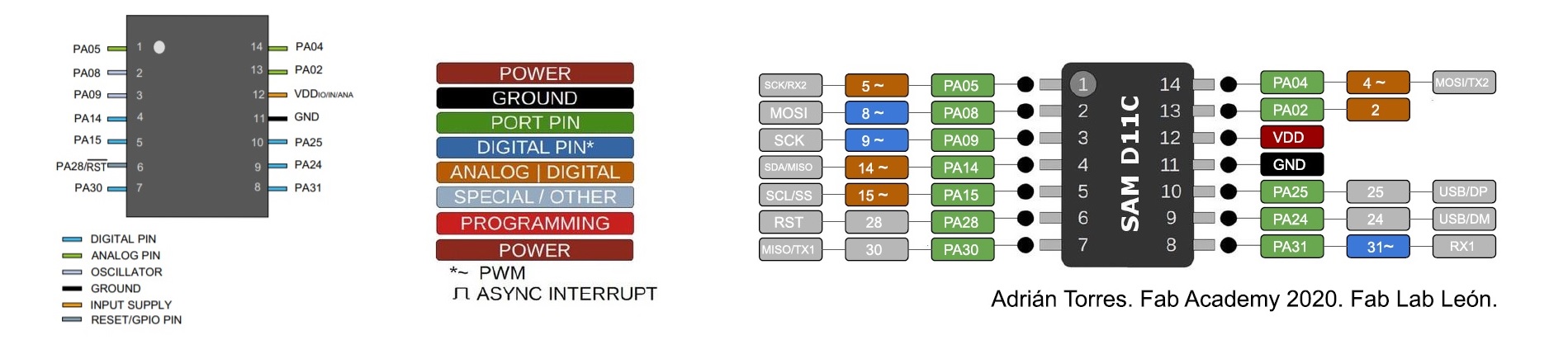
Attribution: from the Samdino documentation by Adrian Torres.
In our case, we will use pins 5 and 8, since those have the capabilities we need, and that’s why we designed the board the way we did.
Learning about Interrupts
I could tell you that I read the datasheet from top to bottom, but no one has time to read 900 pages of PDF.
Please, reward yourself with some “Ain’t Nobody Got Time for That” meme.

Now, I did skim through some pages looking for Interrupt references because interrupt-based logic is something I did want to explore.
The main reason for this interest is two-fold:
- The NERDY reason (To brag about it): So, I heard about this, I read about this, and I was told about this technique, during my bachelor’s degree, by one of the most passionate and fantastic teachers I ever had, but I never had the opportunity to implement it myself at such a low level. Hardware-based interrupts have normally been abstracted away from my everyday life.
- The BUSINESS reason (Efficiency): I also wanted to give it a try, so my processor would not waste processor cycles _ sleeping_ in a loop.
After a quick google, I saw that Arduino supports Hardware Interrupts as well, so this would simplify our process a bit more.
Now that I knew that Arduino had full support for this, I could stop reading the datasheet and I could blindly trust that the abstraction layer will take care of the nitty-gritty details.
To try this out, I wanted to build a small proof-of-concept program.
Goal of the program:
- the user can press the physical button a number of times.
- every time the button is pressed, we increment an internal counter.
- Then, once every 2 seconds, we make the light blink that number of times.
- The clicks accumulate over time, if the user presses the button 2 times, then waits, then 5 times, waits and then 2 times. The LED will eventually blink 9 times with a 2-second pause between each burst.
Benefits of this approach:
- The user can can press the button any number of times while the main loop is sleeping for 2 seconds.
- The button presses are detected immediately (because we use interrupts) and we can see the Serial Monitor (debug) reflect this.
- This interrupt-based approach results in perfect accuracy (no user input is being lost), despite having the main loop sleeping.
There was only one tiny-itsy-bitsy-lemon-squeezy problem:
The abstraction layer is abstracting away the specific realities of this Atmel processor, but it’s not abstracting enough the realities of dealing with the real world! Specifically, we ask our microcontroller to use our ISR (Interrupt Service Routine), every time it detects that the voltage on the pin drops (the FALLING flag), but the realities of using buttons in the real world is that they rely on physical pieces that might not connect and conduct electricity perfectly every single time.
When such imperfections occur, a single user click might result in bursts of short voltage changes as the physical pieces connect and disconnect for a few milliseconds.
This is one of the costs of low-level programming. No library/framework will help you, here.
After “a bit of tinkering around” (this is developer-slang to say “way longer that I’m comfortable admitting”), I put together this software-based debouncing algorithm that can detect fake signals.

The question in your head right now might be: Wait! Why is this needed?
Sometimes, input devices are not reliable, or provide accurate readings that make no sense for the thing we want to achieve.
These simple programming techniques help us breach the gap between:
- the cold reality at the hardware level (yes, technically the voltage dropped 200 times as the button was being pressed)
- to the abstracted reality at the software level (the user’s intent was to press the button only once), because users cannot click one button 200 times in one second

Other useful resources that really helped me during this endeavour:
- I found Julia Ebert’s embedded programming doc to be particularly useful and insightful
- I also enjoyed learning from Joey’s article on why we need debouncing for push-buttons (and other types of inputs) -
This documentation from bucknell.edu also has valuable tips on how to set up interrupts on Arduino.
Some insights when comparing documentation:
Now, most Arduino tutorials indicate that you can read the pins as INPUT_PULLUP instead of INPUT, in order for Arduino to smooth out weird data using an internal 10k ohm resistor.
Quote from: Why we need a resistor to stabilize input from a button
When you set the mode to INPUT_PULLUP, an internal resistor – inside the Arduino board – will be set between the digital pin 4 and VCC (5V).
This resistor – value estimated between 20k and 50k Ohm – will make sure the state stays HIGH. When you press the button, the states becomes LOW.
This is true, but we are not programming an Arduino, we built our custom board with a SAMD11C and a pull-up resistor that’s always enabled, so we cannot use this mode, we need to use INPUT only.
The working board
Check out the working board, including debugging messages on the serial monitor (showing which signals are being skipped)
Working with limited memory (12KB!)
As I was coding the initial parts of my game, I wanted to give it a test on the real board.
That’s when I started having real problems: The real board had physical limitations that the emulator did not have. This brought serious issues:
/home/.../arm-none-eabi/bin/ld: region `FLASH' overflowed by 6456 bytes
collect2: error: ld returned 1 exit status
exit status 1
Error compiling for board Generic D11C14A.
I could fix this by changing the array of doubles[] to int[] int numbers[3] {0};
Sketch uses 10824 bytes (88%) of program storage space. Maximum is 12288 bytes.
And then improved further by changing them to an array of bytes: byte numbers[3] {0};
Sketch uses 10784 bytes (87%) of program storage space. Maximum is 12288 bytes.
Similar memory issues when writing to Serial Console

Just these 2 lines used 7% of my 12KB
  Serial.println("Button = [" + String(digitalRead(BUTTON_PIN)) + "]");
  Serial.println("User click = [" + String(userClicks) + "]");

When you consider how expensive some of these operations are (in terms of the cost/space they require), it makes debugging/programming your board a bit more difficult than I expected.
In most applications I’ve programmed in the past, CPU time or RAM are the two main things to optimize, instead of bytecode size on non-volatile storage.
The last thing to remember is that a single line of code Serial.println() is not that big, but the consumer of space is the libraries and translation layers that this one-liner brings into the final compiled code.
That’s the real cost of using complex/expensive abstractions in such limited systems.
Flash memory is not the same as RAM!
I was confused when I saw that changing byte numbers[1500] {0}; gave the same output (10784 bytes used) until I
remembered that this is the size of the code, not the space used in RAM during execution.
I was around 90% utilization, and I had yet to get into the dirty depths of properly handled interrupts and the core logic of the game.
It was at this point that I decided to dial it back a bit and just explore some simple logic.
RandomSeed seems blocking
In addition to programming the button-with-interrupts app, I also tried some other small games.
One of those games required the board to make a random choice (a random number from 1 to 10).
One issue I encountered when using the real board is that RandomSeed() seems to exhibit blocking behaviour on the real board, but not on the emulator (see below).
I couldn’t find actual references online, but this blocking behaviour is well documented in other systems.
The effect it had on my board was that it could do the init properly, and do a short “welcome blinks” but then it would completely freeze (blocking the CPU while it waited for more entropy), at least that’s what I thought was happening. The blocking behaviour also meant I could not get any other insights into what was going on.
Sudden death of laptop
My laptop crashed a couple of times while programming my board.
Insert #Flashback moment
See Sudden Death Logs for more info and detailed logs.
Custom Firmware - easy mode
During week 8, I was running out of time (in the week) and physical memory (on the chip), so I decided to make a simple proof of concept.
I wanted to test:
- turn on the LED when the button is pressed
- turn on the LED when the button is not pressed
- make the LED blink 5 times when the button is pressed once.
You can see the 3 sample videos at the top of this page.
The other programs described in this document were done during week 9 and 10.
Checking out other tools and platforms
- extra credit: try other programming languages and development environments
During the development phase of this week’s assignment, I wanted to explore other environments and tools.
These are 3 of the environments I explored:
- Platform.io on VSCode (on linux) ⭐
- VSCodium
- IntelliJ IDEA (on linux) ⭐
- CLion
- Arduino emulation on Wokwi ⭐⭐⭐⭐
VSCode (linux) using the Platform.io plugin
How to install Platform.io on Linux Mint
Download VSCode for Linux from the official site. and install it using apt
sudo apt install ./code_1.65.2-1646927742_amd64.deb
Platform.io uses Visual Studio Code (Microsoft) + the Platform.io plugin to provide an IDE
Platform.io can be installed (as a standalone toolchain), but it does not seem to support SAMD11C [1] , [2].

While it supports some Atmel boards, it does not support SAM-D11C.
VSCodium (linux)
VSCodium seems to be a modified version of Visual Studio Code, with no telemetry (nice). Despite this nice gesture, it has even worse support for Platform.io.

It can’t even find the platform.io plugin. So it got uninstalled in less than 10 minutes.
IntelliJ IDEA (linux)
IntelliJ IDEA would have been my preferred method of working, since I’m familiar with the JetBrains family of IDEs. I could find a basic wrapper plugin that allows cpp_check to do basic syntax checking, but nothing beyond that.
Installing cpp-check to validate cpp code
sudo apt install cppcheck cppcheck-gui
It also requires you to install cpp_check manually, so the plugin is basically a wrapper that can highlight lines of code in the editor, but not much else (no refactor capabilities, no syntax highlight or prediction, et…)
CLion with official Plugins for Arduino
I would have liked to try out CLion.
It seems to have better plugin support, from the official marketplace: Official Arduino Support plugin
Unfortunately, since it has no community edition, I didn’t want to start the 30-day trial just yet, but I might look into it in the future (final project?), when I need heavy IDE support.
I’ve been a big fan of JetBrains for years, and I’m expecting that this combo packs a bunch of goodies out of the box.
Emulating the circuit with wokwi.com

See a simplified simulation at wokwi.com
This was a really nice discovery:
It allows us to emulate LOTS (not everything) of the behaviour of our board (not just the microcontroller but also the components attached to it!) and it provides semi realtime simulations of the behaviour and the outputs.
It could not emulate everything perfectly:
- In order to generate pseudo-random numbers, we need to initialize the random generator with a seed.
- The emulator was able to simulate a random seed with faking noise into an analog unused pin, but on the real board, the seed always ended up being the same and the sequence of “random” numbers was always the same, making the game a bit boring.
- The emulator assumes infinite memory. so the first iterations of the program were too large to fit in memory and
would get
region 'FLASH' overflowederrors.
Assets
- interrupts.ino - The application that accurately detects button clicks using interrupts