Press Fit Kit - Castellers
Assignment
- design, lasercut, and document a parametric construction kit ✅
- accounting for the laser-cutter kerf ✅
- which can be assembled in multiple ways ✅
- and for extra credit include elements that aren’t flat ✅
Background
Catalonia has a centuries-old tradition of building human towers, called Castellers.
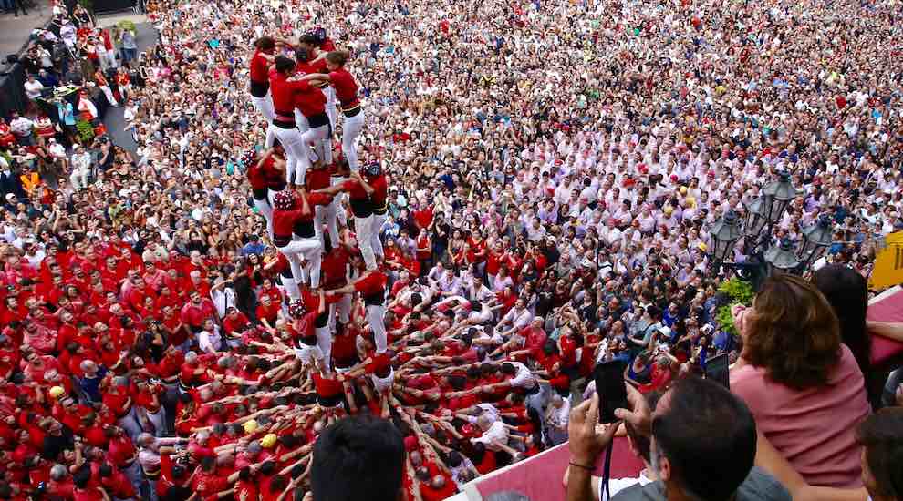
Above, a Human castle being built. UNESCO Heritage since 2010.
Rule #1 - All market-disruptive products begin with a stolen idea
tl;dr/disclaimer: 💡 The idea of trying to build a press-fit building kit of Castellers was shamelessly stolen from
altruistically offered to me by Lonnie. Thanks for
the great suggestion 😉👍🏻
✨ Story time ✨… put yourself in my shoes:
It’s Thursday morning, and I had just entered the FabAcademy classroom in Barcelona. I was just getting setup for the day, when we started talking with Lonnie about local traditions and festivals around the city, when he suggested building a Castellers set for the press-fit kit assignment, I was immediately blown away by what an amazing idea it was, and also taken aback of not having thought of it before.
I was really excited to give it a try, and I was also relieved that he actively encouraged me to give it a try without worrying about future lawsuits over intellectual property! 😅 Thanks mate!
This week’s objectives
The goals for this week’s project were:
- Explore the tolerances of your equipment (kerf, joint clearance and types), and document them as a group .
- Build
a press-fit construction kit
- When designing it, account for the tolerances that you have discovered and adjust your measurements/sizes.
- Make the pieces in your design parametric so that they can be cut on different materials (of different thickness).
- That is: at the very least, don’t hard-code the thickness of your preferred material into your design. Let the users who consume your designs adjust the parameters, so they can also laser-cut it, without having to modify the actual design file.
- Explore things beyond the basic press-fit features (living hinges, non-flat pieces, etc…)
Iteration 1
Initial idea
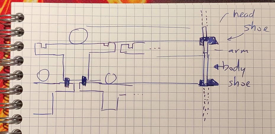
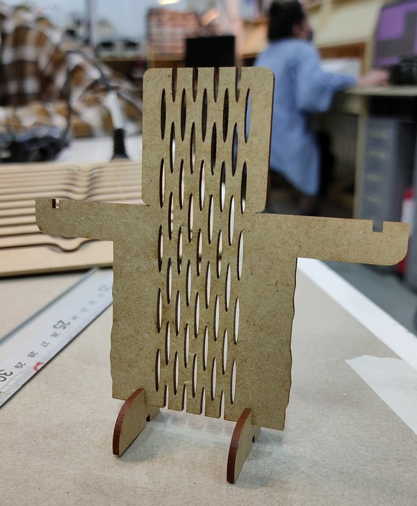
The initial idea was to have a press-fit kit that is composed of 2 different types of pieces that will snap together at a 90-degree angle.
- The body
- The foot
Each person will be composed of 1 body piece and 2 feet pieces, which will allow them to snap onto 2 other people below them, or stand on the floor, if they are on contact with the ground.
As a future improvement (an outer ‘nice to have’ spiral), I thought of designing a large ‘ground base’ so that all the feet from the lowest floor can snap solidly, to improve the overall stability of the tower.
Creating a living hinge
One of the things I wanted to achieve was to build something somewhat realistic.
As you already know, from the picture above, Castells are not built as a 2D human-wall, but as a 3D human tower with a circular profile. This gives the participants a way to balance each other and compensate small deviations and tremors.
So, I wanted to find a way to achieve a similar look: layers of circular rings stacking on top of each other.

This is where a technique called Living Hinge comes into play.

A living hinge allows us to make bendable pieces out of flat materials. By playing with the sizes of the cuts, their angles, positions and widths, we can have control over how strong and how flexible the hinge ends up being.
Living Hinge: Using pre-built tools
During one of the local lectures, we were told that there are various products/plugins that can be used to build living hinges.
A quick search returned a living hinge Extension for Inkscape, among many other useful results.
- On the one hand, it seemed interesting to explore how to install Inkscape plugins in order to extend its basic capabilities.
- On the other hand I kind of wanted to try out designing the living hinge “by hand” in fusion360 so I could practice some of the things we did the previous week (Rectangular Patterns, etc.)
I was blessed enough to be able to do both:
- I managed to install the Inkscape extension.
- Then I saw it fail when attempting to create living hinges with specific parameters.
- … and thus, I had the golden opportunity to give a try at creating the living hinge manually.
Below you can see how the Inkscape plugin crashed during the operation. Based on the error, it seems that the plugin might be using deprecated methods for parsing user input. This could happen if the plugin was created for an older version of Inkscape and the developers did not have time to upgrade their code to support the latest inkscape version.

Since I had already learned how to install plugins for Inkscape, I decided not to spend more time on this and to move on to the manual approach.
Living Hinge: Manually
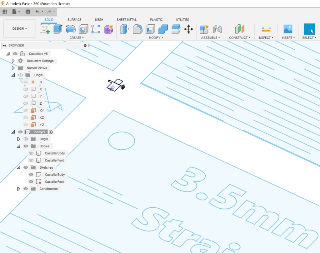
Fusion360 allows us to create two types of repeating patterns:
- Rectangular Pattern: which allows us to make horizontal/vertical/orthogonal/cartesian repetitions of elements (pick your favourite term).
- Circular Pattern: which allows us to make Polar repetitions (same radius/distance from the center but different degrees [º] of separation).
For the living hinge we needed to use the first type, since we want the hinge to repeat itself across a rectangular area
This is what the design ended up looking like:
If you look closely, you will surely notice the 2 main colours:
- black for constrained elements
- blue for unconstrained ones
This was confusing to me, I was expecting that the pieces that would come out of applying a “Rectangular Pattern” to a set of fully constrained pieces, would also be fully constrained, since they all are:
- extending the constrained elements, and repeating them over various different positions.
- the new positions for the elements are well calculated and extremely well-defined according to the parameters of the rectangular pattern (since we have to specify the separation for each row, etc.)
Turned out not to be the case (thus, the blue elements in my design): After a quick duckduckgo search, I came across other users on the AutoDesk forum asking themselves very similar questions
It seemed that this behaviour has been occurring for the last 6 years, since the feature was originally developed. I asked around during local review, in case I had configured something wrong, but no one was able to explain the root cause for this counterintuitive behaviour in Fusion360.
Other people also talked about how this behaviour is normally caused by the wrong order of operations , but in my design, the changes I’m making are being done well after the initial two rows of the hinge are completed, so that doesn’t seem to apply.
Accounting for laser tolerances and kerfing
Something that we learned during our group project for the week was that each device might have different tolerances and precision (just like regular printers).
The issue is that for laser cutters, these tolerances are critical, since a small fraction of a millimeter can cause our pieces to no longer fit into each other.
This is why we have to actually measure and then account for the kerf during the cutting process.
Since we did our group assignment on Thursday, we were able to determine that our laser cutter could be off by 0.15mm during cutting, not because of incorrect calculations, but because this would be the size of the material that would be burned off/evaporated during cutting.
This is why we had to adjust our designs.
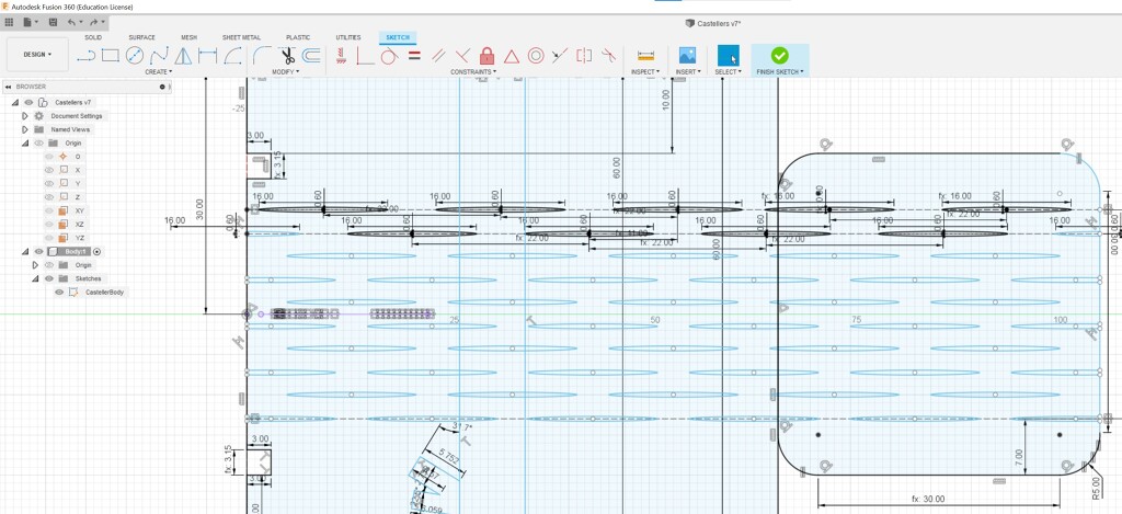
If you look below, you will see how the proportions and sizes had to be adjusted to account for the 0.15mm difference.
- The places that show “3.00mm” are set manually (since this is the depth of the insertion, and unrelated to the thickness of the material).
- The places that show “fx:3.15mm” are calculated from the parameters.

And this is the result of orbiting around the design of one of the press-fit pieces.
Building the pieces
As you can appreciate in the picture above, lots of things went well
- ✅ Living hinge looks good and works
- ✅ Proportions and size
But some other things need improving:
- Press Fit is loose and needs to be adjusted further:
- The material thickness needs to be measured again because it seems that the initial measurement was more “faith
based” than “empirically checked”.
- This means changing the design of the shoe so that the two snapping teeth are not offset instead of being “one directly on top of the other”, since the show is not tall enough to support deeper teeth
- The depth of the press fit should be 2x or 2.5x the material, to make sure it can be embedded deep enough.
- Pro tip from local instructors: add chamfers to the teeth, to help during the insertion
- The material thickness needs to be measured again because it seems that the initial measurement was more “faith
based” than “empirically checked”.
Iteration 2
For iteration 2, I wanted to fix all the issues I discovered during the first attempt.
- I corrected the material thickness
- I improved the press-fit joints
- Added Chamfers
- Increased the joint’s depth
- Changed the positions of the joints on the shoe so both sides can slide into it easily
- I made some other changes to the design, which lead to some interesting lessons learned (how and why I was setting up my constraints poorly)
- I improved nesting in the final design
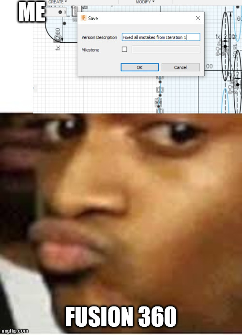
Issues and lessons learned
The tyranny of floating point precision
During one of the adjustments of the design, I noticed that one of the “closed curves” had suddenly changed to “open curve” and was not being extruded anymore.
This was very confusion and unexpected, since I assumed that Fusion360 would keep the “snapping” behaviour of all of its points.
This was further aggravated considering that the change I was making was not (apparently) modifying the positions of the affected curves.
Upon closer inspection, I noticed that the issue seemed to be caused by what we will call “the tyranny of floating point precision”.
The two points were extremely close to each other, but there were not fully snapped, so when a small change triggered a recalculation, they got rounded off to different positions (separated by a mere 24.8 nanometers).

In this post you can read more about floating point precision and why these issues occur when representing numbers in binary
Importing files built using a different scale
Before I tried to use the Inkscape plugin for living hinges, I decided to download an existing design for living hinges and see if I could “apply it” on top of the figure I had designed.
And this was the result:
Either my design was out of scale (and I had accidentally designed it in nanometers), or the template I had downloaded said “3.5mm” but actually meant “3.5 meters” 🤔💭
After a quick look at my notes, I came across a “tip” shared by Josep, one of the local instructors:
Remember to check the units when importing files, always make sure they are all in the same units, or adjust the proportions manually.
Sure enough, once I converted the inches to mm, the file appeared to render correctly.
Confirming our hypothesis
Step 1: calculate the inch-to-mm ratio:
- 3.5 inch = 88.9 mm
- 1 mm = 0.0393700787402 inch

Step 2: Load the file using the calculated ratio (to effectively convert the file, which was designed in inches to the right scale for mm.)

Step 3: Use the built-in tools to measure the distance between each of the cuts.

Step 4: Confirm that our suspicions were correct. The file was designed in inches.
Since the file for living hinges only contained “straight line” hinges and we wanted to try the oval shaped ones (which seemed to offer more flexibility), we eventually decided to build the hinges manually.
Fusion360 cannot easily export DXV files without construction lines
Apparently, Fusion360 has a well known feature/problem when exporting DXV files. If the sketch that you are exporting contains any construction lines, those will be exported as well.
This results in extra workflow steps when opening those files up in another program (we need to remember that they have to be cleaned, figure out which elements must be removed, etc.)
A popular solution that I found was:
- Extrude the figure you want to export
- draw a new sketch on its surface
- Export that new sketch instead of the original.
This will export just the extruded part, and leave any construction/invisible elements behind.
This is useful, but it also means that you cannot use Fusion elements to designate “parts to engrave” (for example), as those parts would not normally be exported, since you would normally extrude them normally.
The unstoppable train of reality (has no brakes), don’t underestimate it
After having done the group project (Thursday), and having spent some time building a parameterized model during the weekend, while also accounting for the kerf specific to the Laser cutter in our workshop, the Unstoppable train of reality entered the scene on Tuesday (the day before weekly presentations).
As it turned out, all the materials that were available to be used (cardboard, MDF, etc.) had a thickness that did not match the one that was presumed to be, during the design phase.
Fortunately, the design of the elements was parametric, so I was able to adjust and print a proof of concept in under 15 mins, but the lesson remained.
Measure twice, cut once - Proverb
Lessons learned …
…during the group work done during this week
This week we paired with Dhanu on part of the group project for the week
We picked Acrylic (you can see the full doc on the group projects page).
These are some lessons that I learned while working on the group project:
- Shades of colours when rastering
- So, it turns out that JobControl software is able to not only detect different colours, but to measure their saturation (on a 0% - 100% scale). This is useful during rastering, if we need to raster lots of different shades (e.g. images in grayscale instead of just black&white).
- This inevitably led to a deep appreciation for the logic that’s hiding behind the drivers and tooling. The system not only needs to easily calculate and determine that this █ is shade of the color tone affectionately called Petrol █, but also that it’s the lightest possible shade of Petrol that exists, and thus it will have to treat it with the settings that we assign for _ Petrol_, but reduce them down to 0.1% since it’s very washed-out.
- Text vs TextObject
- Some Rhino commands seem to do similar things but they have very different purposes, when it comes to laser
cutting.
- Text: this command can be used to raster (and fill in) text
- TextObject: this command can be used to engrave the contour of text (without filling)
- Some Rhino commands seem to do similar things but they have very different purposes, when it comes to laser
cutting.
- Laser focus: We should have measured in the middle of the material
- When we tried to laser cut the sheet of Acrylic we noticed that some small parts that were supposed to be fully cut were not coming off easily.
- This was because the laser was not fully converging “in focus” when traveling other those areas.
- We then remembered that we should have calibrated the focus of the laser in the middle of the cutting area and not on the corner of the bed.
- Living Hinges with Acrylic, they are brittle
- Another lesson learned was that Acrylic living hinges are very brittle.
- Eduardo shared that creating parts (especially press-fit pieces) using acrylic is delicate because the material has little give. Hinges and Fillets should be used liberally.
- Metacrilato, is the name for Acrylic in Spanish
- The last lesson I learned is that Acrylic is called Metacrilato in Barcelona shops.
- I went to purchase a matte-orange sheet of Acrylic, but the name was so different that I started to doubt whether these were the same material, or if they were different materials with different properties.
- The Safety session for the laser cutter made it very clear that were not supposed to use the cutter on “unknown” materials since there were potential risks to health/contamination/pollution, so making 100% that these were the very, very, very same material seemed like a small obsession, and it very much was.
Iteration 2
Iteration 3
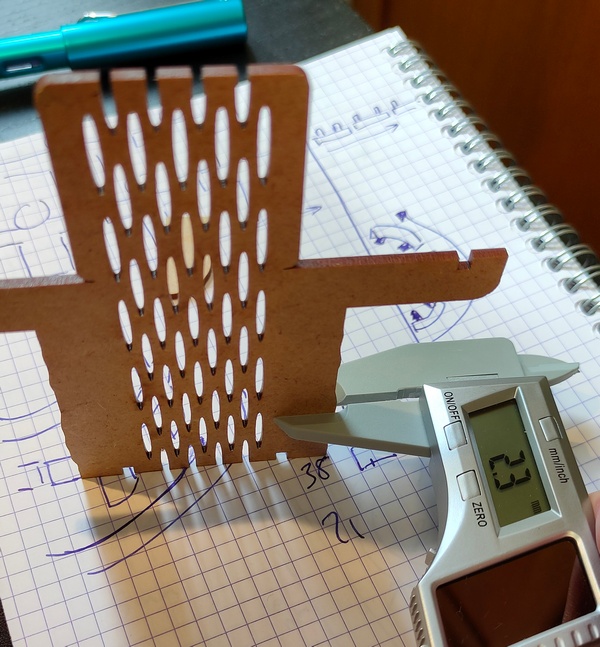
Caliper’s precision
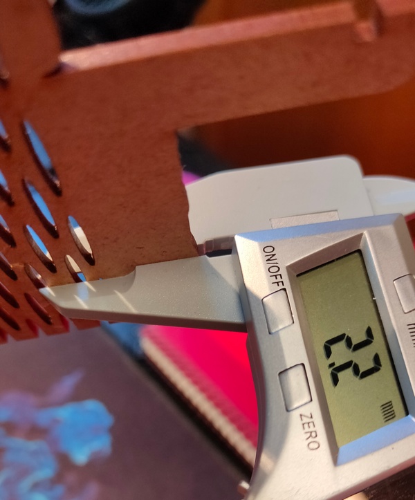
The following reading showed that either:
- the concept of depth is made up and does not exist in reality.
- or that the caliper’s accuracy was suboptimal
It turned out to be the second case:

With an accuracy of +/- 0.2mm, this caliper can provide somewhat accurate measurements, but these are not precise enough to measure the depth of the material for a super-precise press-fit.
So we will use 2.3 as the measurement, and if that’s too tight, we will press the pieces a bit harder.
💡 As a general reminder, it’s probably better to lean towards “too tight” on materials that are easily compressible.
Kerf is supposed to be subtracted!
The other lesson learned is that Kerf is supposed to be subtracted, not added!!
So, the nice 360’ video that you saw above, actually shows a mistake, despite the beautiful traveling around the fitting.
This is what the fitting looks like after correcting for kerf (thickness - kerf instead of thickness + kerf)

Iteration 3
The finished product: a 3-tier human castle, where all the pieces fit together to form round layers of people holding hands.
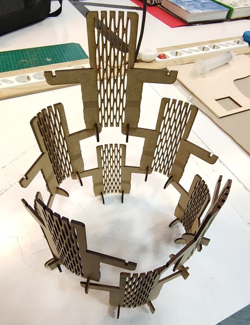
Despite there only being 20 pieces, this took over 40 minutes to laser cut.
The living hinges, while useful for extra credit (sure!), are really expensive when it comes to allocating and budgeting time on the cutter.

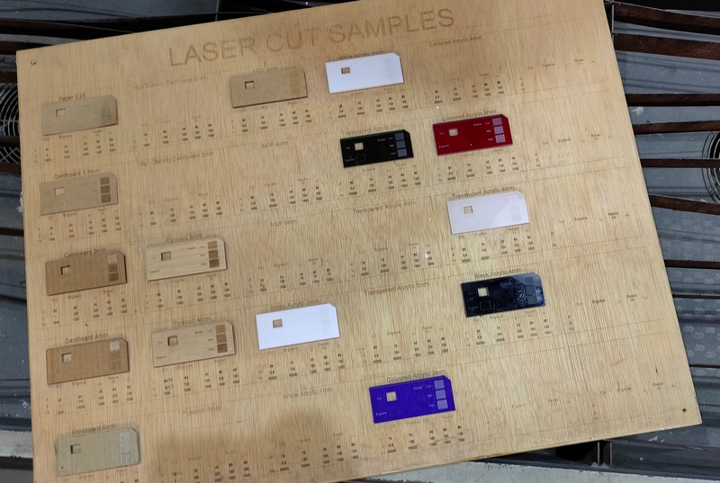
Cheatsheets
Laser Cutter Settings - Cheatsheet board
A cheatsheet for the most common settings for different materials.
Engraving Colours
A cheatsheet for laser cutting - JobControl for Trotec Laser
| Color | HEX | Purpose |
|---|---|---|
| █ Black | #000000 | Raster Engraving |
| █ Red | #FF0000 | Line Engraving |
Cutting Colours
| Color | HEX | Purpose |
|---|---|---|
| █ Blue | #0000FF | Innermost cut |
| █ Petrol | #336699 | ........ Available if needed |
| █ Cyan | #00FFFF | ........ Available if needed |
| █ Green | #00FF00 | Second Outermost Cut |
| █ Magenta | #FF00FF | Outermost Cut / Most external Boundary/Outline, literally the last thing to cut |
| █ Yellow | #FFFF00 | Never use it.. Rhino uses yellow for “selecting” and it will be very confusing! |
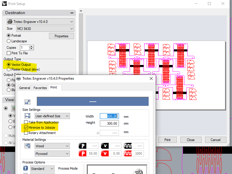
Remember to enable
- Vector Output (a previous student disabled it and the laser was not cutting properly and defaulted to engraving everything)
- Minimize to Jobsize (so that you only export the min. area possible)