10. Moulding and casting
This week we learned the molding and casting workflow.
Group assignment
Our group assignment this week consisted of reviewing the safety data sheets for materials available. Since we had food grade silicone available, I became inspired to try making an ice mold
Ice shot glass
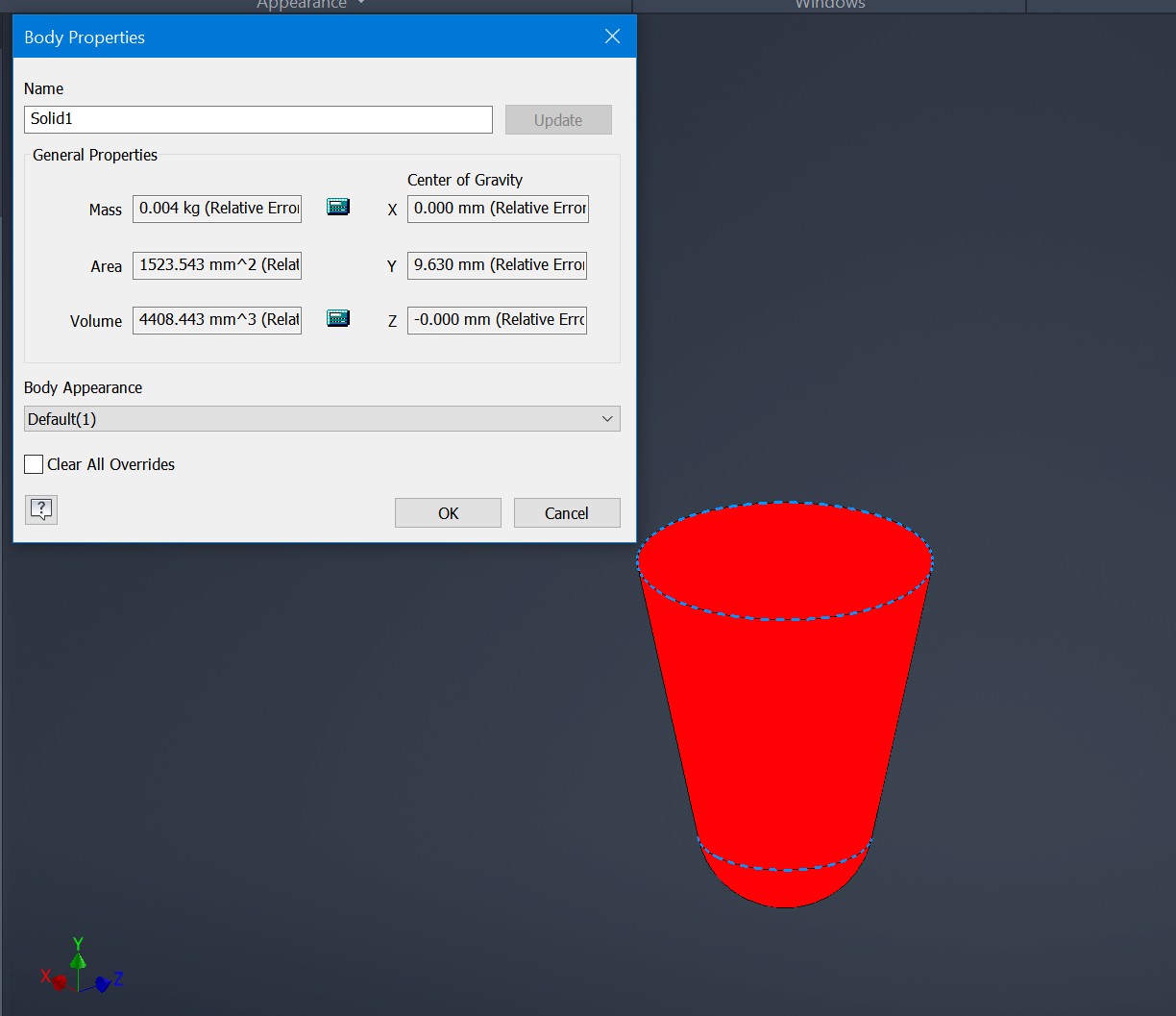
We start by creating a revolve of the “drink” volume itself. Shot glasses are supposed to be 4cl, ours is 4.4, so that should be fine. This will be a cavity in the final model. So it’s actually a negative model.
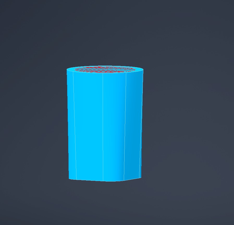
From the same sketch we can revolve the counterpart as a separate body. This time it’s a positive
With only one shot glass I’d have to drink alone. Sad. Lets pattern them out
Now we need to consider positives and negatives. My head already hurts. Our final mold must be a negative of the shotglass, but to make that mold we need a negative of the negative - a positive. Our lower part is already a positive. So if we make that into a mold, we will get a negative which is what we want.
Our upper mold is a negative, so we need to negate that to make a positive to make a negative. We can use a boolean subtract for this.
With me so far? good.
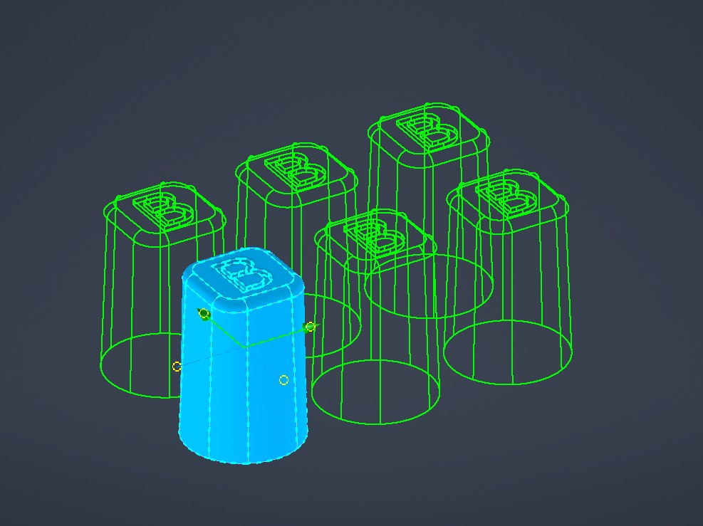
With the parts sketched on top of eachother, nothing makes sense. Lets move into assembly to make it clearer to see
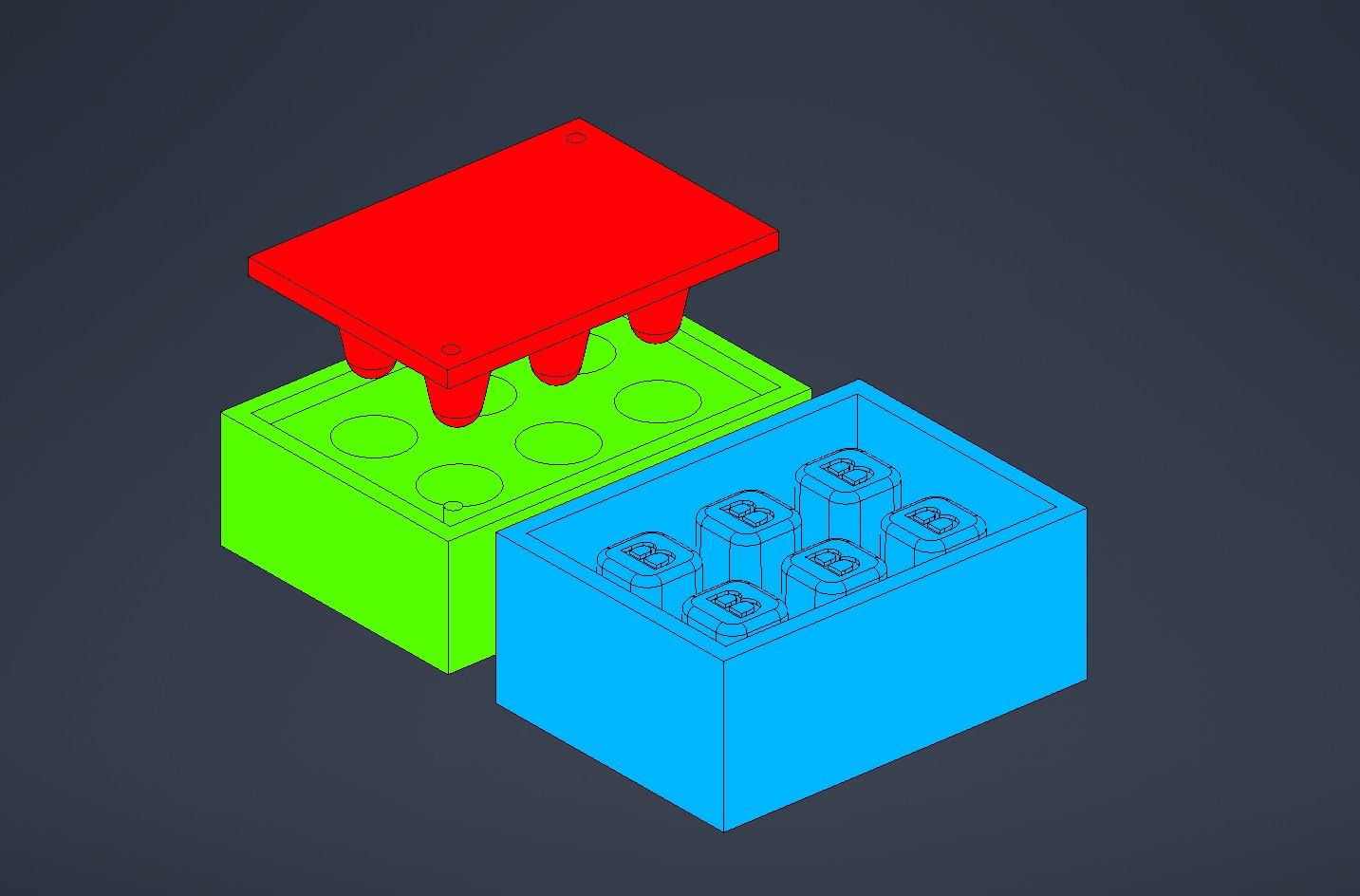
We have our original negative in red, and our positive molds in green and blue. Note the aligning pins.
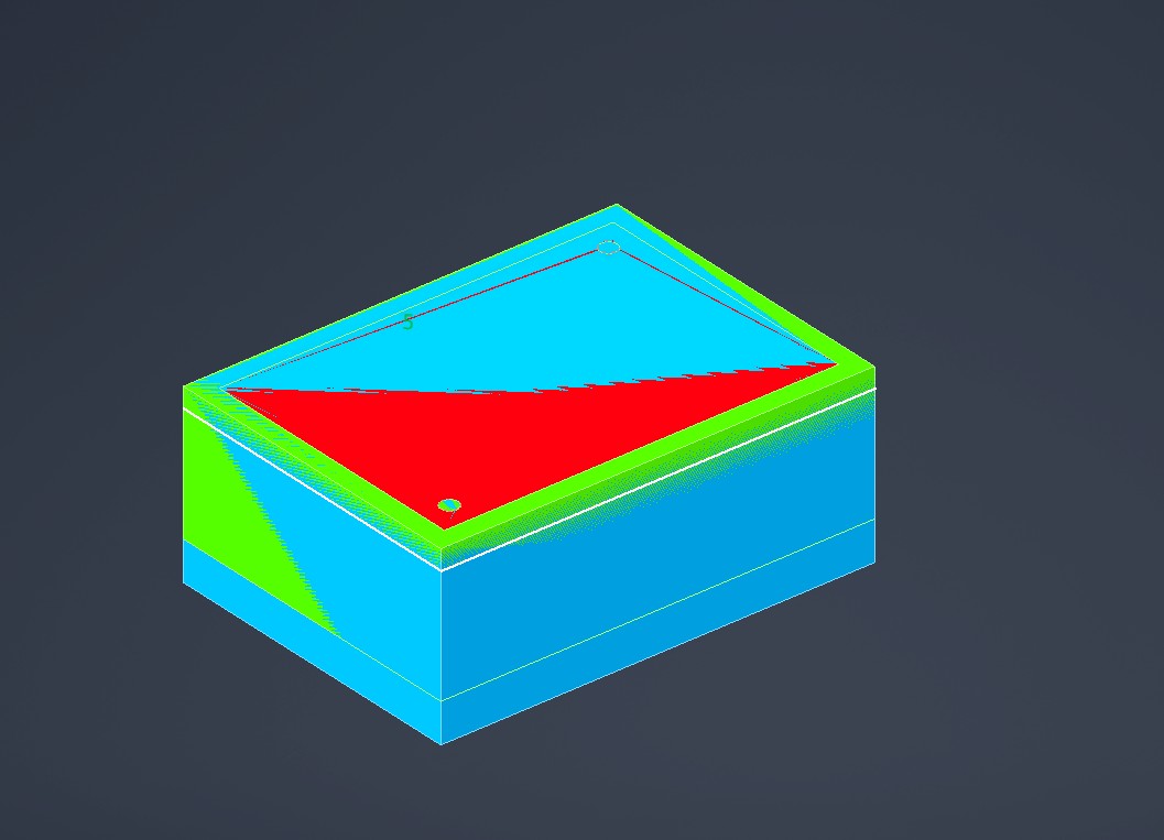
We can negate the lower mold as well to see what our final negative mold will look like:
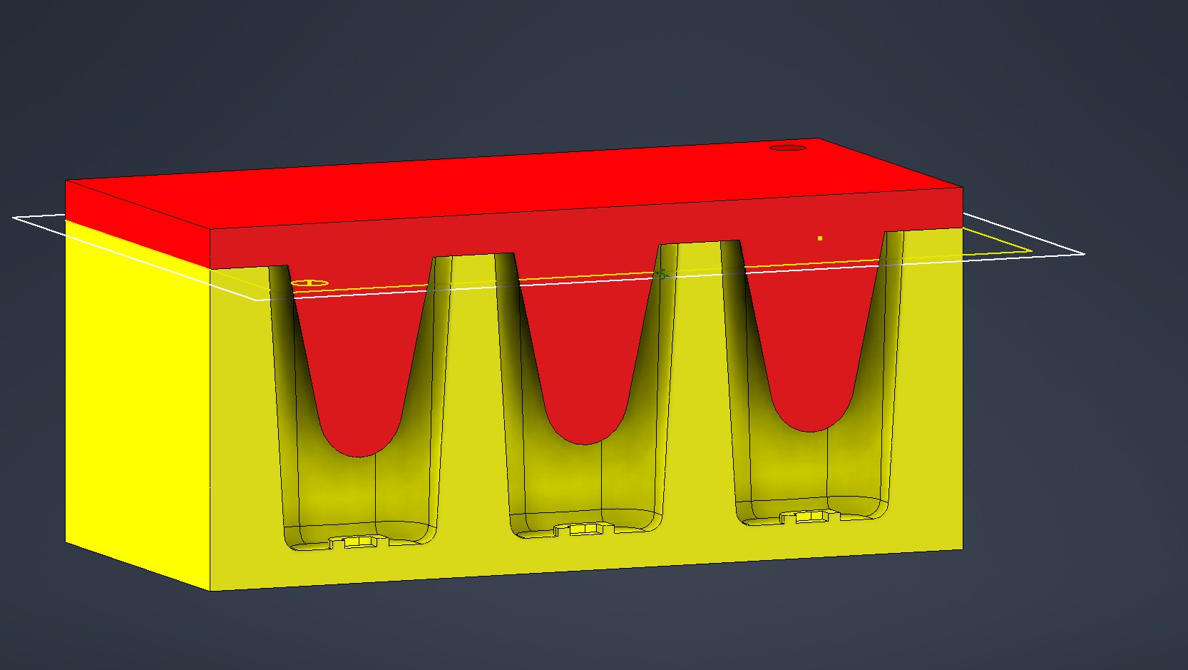
With a section view we can see inside. At first I was worried that we need to design venting holes etc. But seeing that we will use water, a low viscosity fluid, this should be fine.
MDX-40
We will use the Roland MDX-40 mini mill for making the molds for the molds. The mold-molds, if you will. Technical specs below:
| MDX-40 | Technical specifications |
|---|---|
| Work area (XYZ) | 305x305x105 mm |
| Spindle motor | Brushless DC motor, Maximum 100 W |
| Spindle speed | 4500 to 15000 rpm |
| Feed rate | XY: 0,1 - 50 mm/s Z: 0,1-30 mm/s |
| Material | Wood, resin, wax, plastic. |
The MDX-40 is quite similiar to the SRM-20, from electronics production week, and indeed, it can be configured for PCB milling as well. The MDX however has a sturdier frame, spindle speed control and an optional fourth axis, which can be used for general milling work. Like the larger Recontech, it also has a neat Z-probe, making Z-axis zeroing easier.
This machine is designed for soft materials with a belt driven spindle, so care has to be taken in ensuring that the toolpaths aren’t too hard on the machine. In the worst case, the belt will slip, the tool will grind to a halt, and the mill will continue feeding it into the material until something breaks. And that won’t be pretty.
CAM
As usual, we are doing CAM in Inventor’s CAM module.
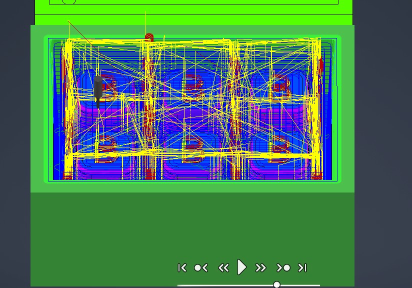
As a general rule, we will use a 3D pocket for roughing, and a 3D contour for finishing. For tools, we fortunately have quite long 3mm flat and ball mills. For the engraves on the shotglass bottoms, we will use the 1mm PCB flat mill, which fortunately the MDX-40 supports!
Inventor has a couple of Roland branded post processors pre-installed. The RML processor doesn’t seem to work, but the ISO processor spits out what appears to be generic nc code. Let’s roll with that.
Milling
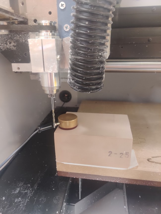
We need a 110x80x45mm stock piece for our bottom mold. Unfortunately, there weren’t wax pieces big enough around. Instead I’ll use a material called Sikablock.

(Sika means pig in Finnish. It’s funny I swear)
The real sikablock is a hard-ish plastic. Its widely used by machinists for test cuts, jigs etc.
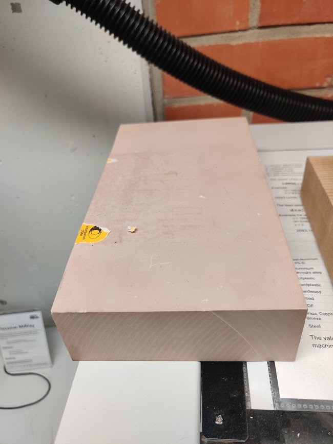
The sikablock I have is 50mm thick. It turns out that the MDX-40 only has 105mm of Z travel. This means that even at max Z, the inserted bit isn’t tall enough to clear the Z probe. Instead, I’ll have to zero Z the old fashioned way… Fortunately, for this mold an extremely accurate Z isn’t important. For the same reason I’m not using a planing operation.
Let’s get to milling!
The long bit clearly causes quite a lot of resonance. Ear protection is recommended.
What is also recommended is tightening the milling bit properly. The climb operation caused the mill to dig itself in, and ruining my first piece :(.
Fortunately, the two sided tape broke before the machine. Otherwise I’d be in real trouble!
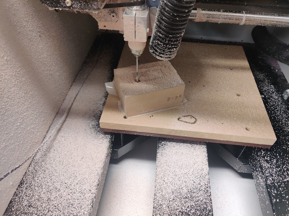
I got a new piece, attached both the piece and bit better, and turned the milling speed to 70%.
Now we are cooking! With a small tool and 70% speed, this will take a while…
The jankyness of the movement is probably since i forgot to put on smoothing in CAM!
The climb milling is lifting the chips out of the pocket, but there is quite a lot sticking to the top of the part. Fortunately, the roughing pass will leave a slight amount of material unmachined, and the finishing passes will have much less material to deal with.
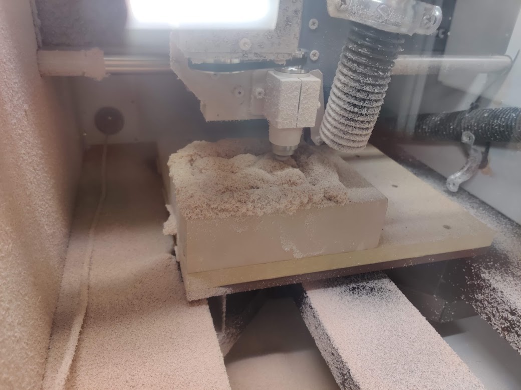
About 3h of milling later… We are done!
The results are really nice! For some reason, my plane finishing step straight up ground away a couple of mm. Weird.
next step is the upper mold part.
At this point, the little CNC mill was in near constant use, so I decided to try 3D printing for the opposite mold part.
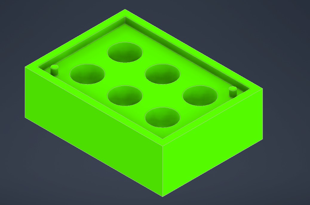
The model at this point is not optimized for 3D printing, let’s fix that. First, we delete the bottom faces.

We have now turned the 3D model into a surface, in fact, the minimum surface necessary for the mold.

Then. we give it a bit of thickness, this way, it is printable with the minimum amount of material.
Cura has a neat feature called make overhang printable. This means that horizontal overhang is made 45 deg. and extended to the closest support.
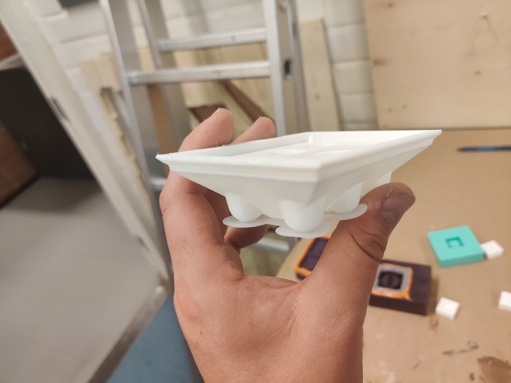
3D-printing was a lot more convenient than milling!
Casting
For making our final mold, we are using foor grade silicone
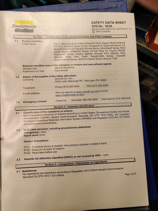
According to the datasheet at least…
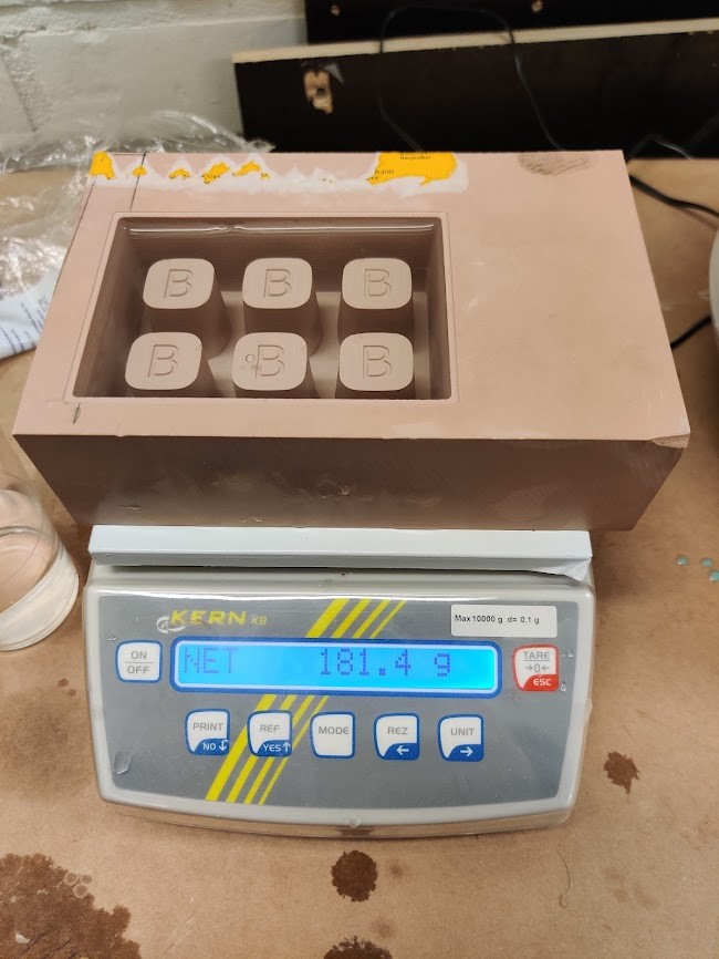
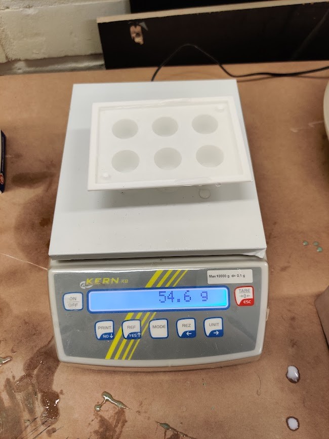
I filled both molds with waster, and measured the tare weight. We should need approx 225g of silicone (assuming the density is about the same)
On to mixing. THe silicone comes in two comoponents, which are mixed in a 1:1´ration, both weight and volume. After this, it is thrown in a vacuum chamber to suck out the excess air.
This step also took quite a while. I was running out of time, so I didn’t bother getting all the air out. This mold is regardless a prototype.
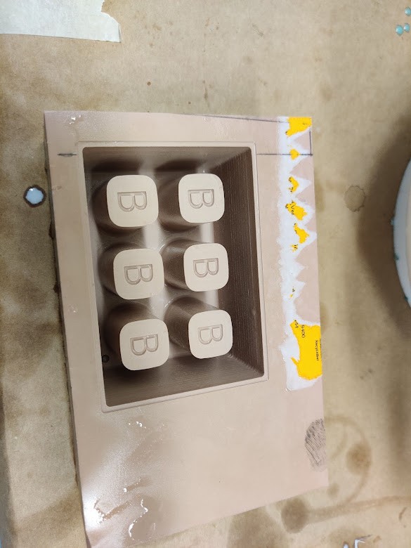
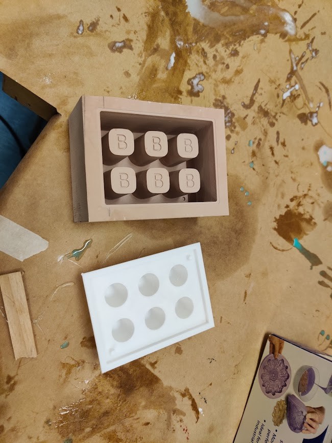
It turns out that I have way less silicone than needed. I barely got one of the molds filled. I therefore have only one functional mold out of 6. Should still be valid to probe the concept.
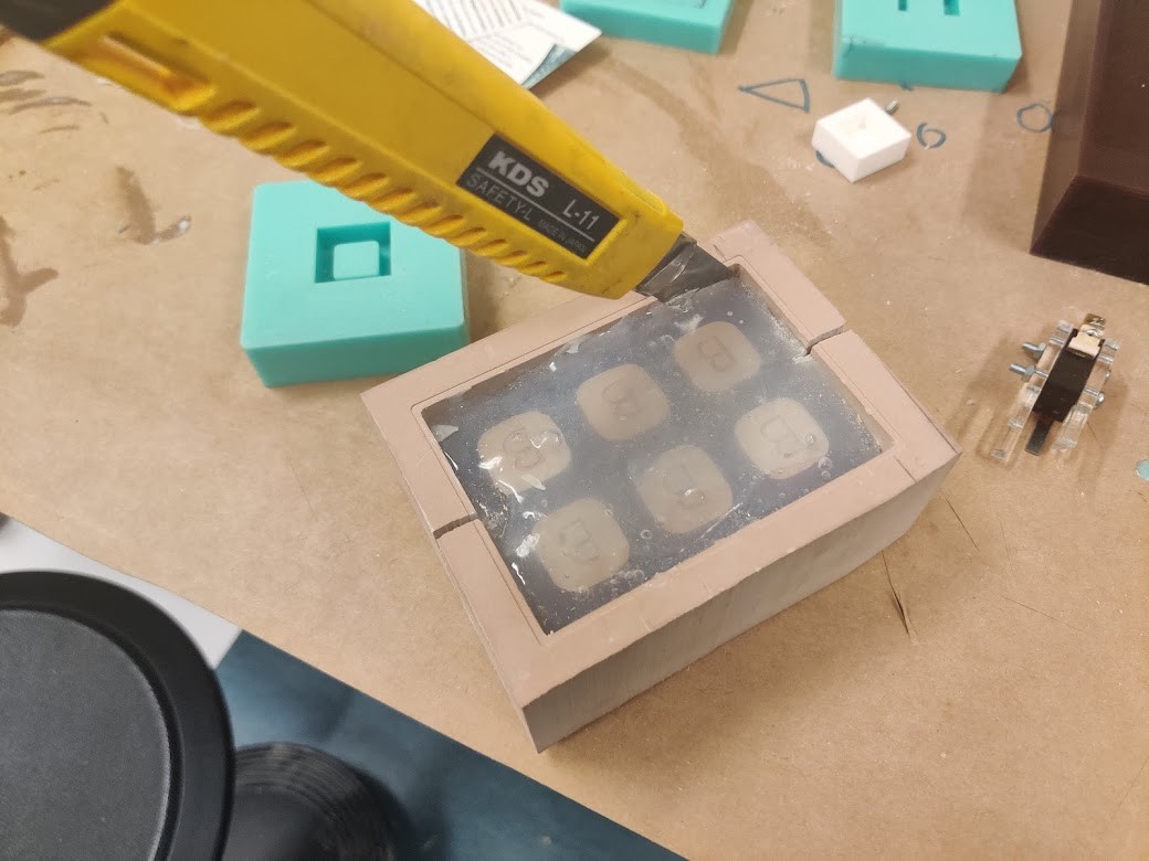
Getting the bottom mold out turned out to be extremely difficult. With a combination of box cutter, saw and Finnish swear words, I finalyl got it out. Mold was destroyed in the process though.
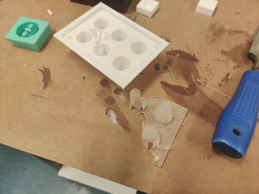
3D printed mold worked much better, and the silicone was easy to remove.
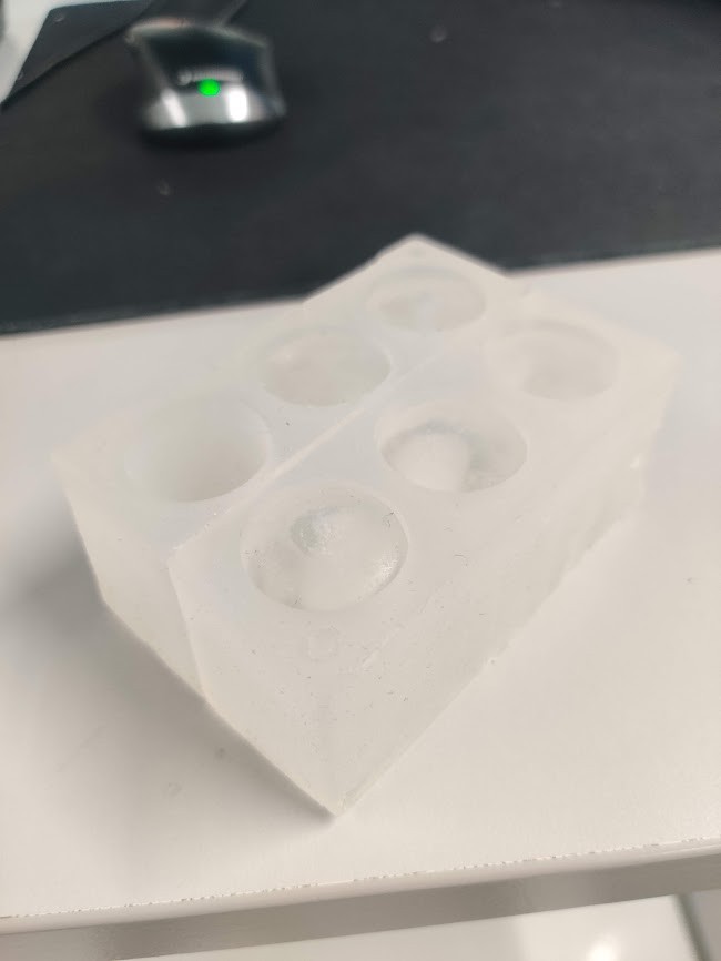
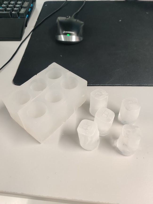
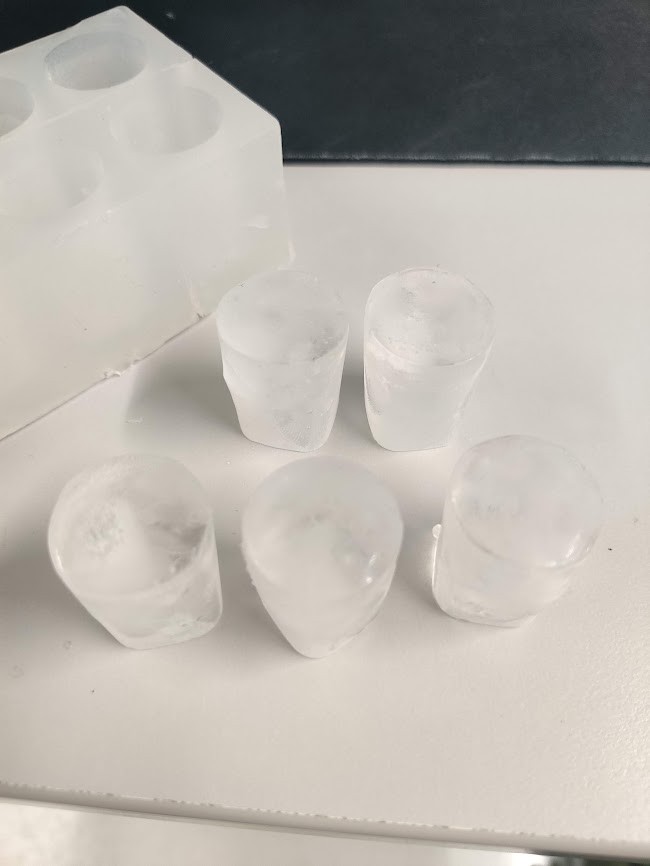
Finally, some photos from testing. These became fancy ice cubes instead of shotglasses, as they are too small. For the nbext revision I’ll learn to do unit conversions…
Design files can be found here