14. Networking and communications
This week we make two microcontrollers talk to each other in their own language!
Group assignment
I teamed up with Saskia to try serial comms between two random board. See our group assignment here
In brief. We got serial communications quickly working between two entirely different microcontrollers. Yay UART.
Adressable leds, WS1812b
For a networked system I have an obvious application, my final project’s addressable led system, often called neopixels.
I’ve written a general summary of the neopixel programming here. Let’s however here take a deeper look on how this is achieved on the technical level. Datasheet time
As the LEDs are on a single line, there isn’t a dedicated clock line, unlike for instance SPI. This means that staying within timing parameters is critical for a readable signal.
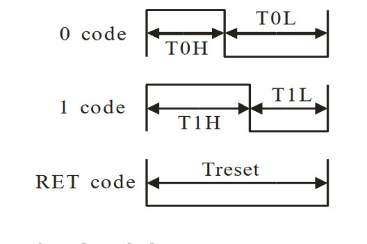
As can be seen in the diagram, a binary 0 is represented by a high signal of 0.4us followed by 0.85us low. A 1 is reversed, with a 0.8us long high and 0.45us low.
Total transmission time for a single bit is 1.25s, with an allowed error of 600ns, that’s an error marginal of 48%, which is surprisingly high. That’s however cumulative, as the individual high low times have an allowed error closer to 20%. 1.25us translates to a data rate of 800kHz.
The desired RGB color is transmitted in fixed size 24 bit blocks. That translates neatly to 8-bit values for each of the three colors. In a WRGB neopixel the data block is logically 32 bits. This control value then sets the correct voltage to each LED segment using the built in voltage controller.
How then can we code address an individual led? Easy.
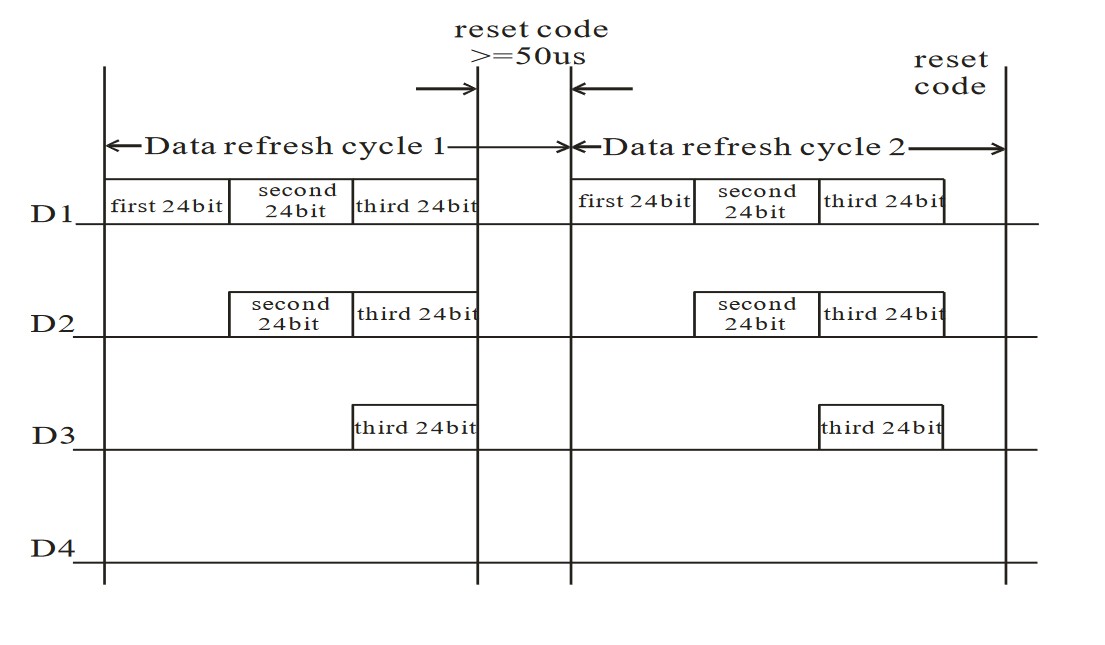
After a LED receives a 24 bit data block it then starts forwarding following data to it’s data out line. In other words, the LED passes on following data blocks to leds further up the chain This repeats until a reset code (a low of over 50us) is sent, making the LEDs accept instructions again.
For the code to address the LEDs, it needs to know beforehand how many there are in the chain, to essentially pre-address each 24 bit block before sending the chain.
For videos and what not of the LEDs working, I suggest heading to my final project
Interesting calculations
Having read the datasheet, we can calculate some characteristics for our application. In this case, my final project.
The final project has 10 LEDs. every LED requires 24 bits, thus the total bits per refresh is 240. Let’s call this a frame.
with a 800kHz bit rate, each frame takes 300 us, to transmit. Adding a 50 us reset delay, we get a total frame time of 350us. Thus, we have a theoretical framerate of 2857fps!
As movies often use 24fps, we are clearly not near the limits of the protocol yet (Fun fact, getting to a 24fps refresh rate would in theory require over 33 000 LEDs on the same line!)
Mic check 2, I2S boogaloo!
So my microphone experiment’s of last week didn’t go so great. I wanted to use an analog mic with opamp, but failed.
Maybe instead we should go digital?
Fablab has these nice i2s mics available, which might just do the trick.
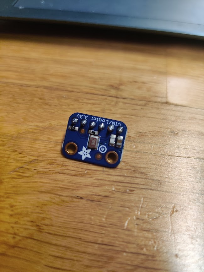
They come in both breakout and SMD variants. I’m going to start with a breadboard experiment and move on to a full custom PCB.
I2S
I2S (or Inter-IC Sound) is a interface standard, specifically designed for transferring digital sound. As such, it has a fairly high bandwidth
WIkipedia has a bit of math to calculate ballpark bitrates.
Let’s assume we’re using stereo CD quality audio. In that case, we have two streams of 44.1kHz samples, with each sample being 16 bit. Thus, our total bitrate is 44.1 kHz × 16 bits × 2 = 1.4112 Mb/s
This bitrate is quite high for an entry level microcontroller. Indeed, hardware I2S support is usually only found at higher tiers of microcontrollers.
For our project we won’t be using a high end chip, so what gives?
For our application, we won’t be needing full CD quality audio, far from it. Our mic is only used for audio level sensing. So quite big spaces in the samples are acceptable. Furthermore, our system is not stereo, further halving bitrate.
Instead of hardware I2S, we can actually emulate an interface in software, courtesy of Neil G himself!
The code is a bit hacky, but fairly simple in principle. The code has a delay function, that actually just completes a certain amount of clock cycles. Then a bunch of reads are done to parse together a 32-bit word from the I2S mic.
Now the trick is to find out how to change 3 bytes in a sample to a single one…
First attempt results:
So, It wasn’t as easy as thought… especially debugging on an essentially one directional circuit is pretty hard. In the future i’ll try to include some kind of serial in my chips, just because debugging becomes much easier. In the end, the mic didn’t work, and I couldn’t figure out why. Therefore, the final project will have to do without a mic for now.
Teensy
On the other hand we had some Teensy microcontrollers laying around fablab.
It turns out that these are really nice for a few reasons:
- 32-bit processor ARM processor, with loads of juice
- Easy programming through USB and the Teensyduino extension. Also most arduino code translates nicely.
- Libraries for both neopixel and I2S.
My first attempts were on a Teensy LC, but it turns out that the “low cost” aspect means that I2S functionality is cut out.
Instead, I went for Teensy 3.2, a very similar but higher performance chip.
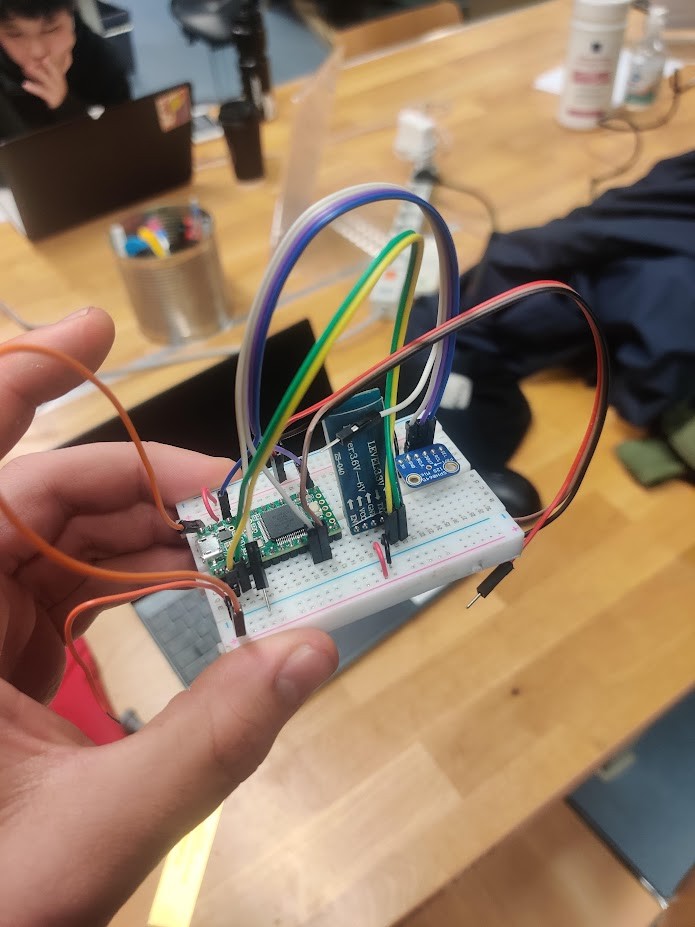
Development boards are also nice, since they can be built on a breadboard. This means that wiring errors take seconds to fix, instead of using hours to make a new PCB ( ask me how I know....)
For audio in general the Teensy manufacturer has provided a Design tool
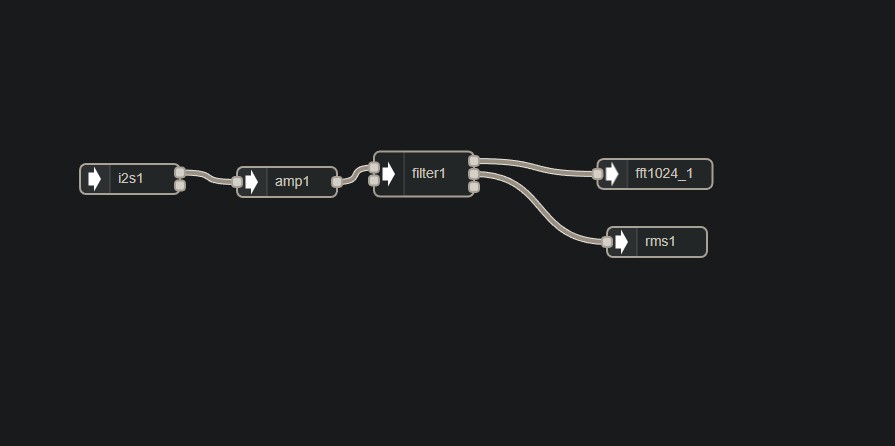
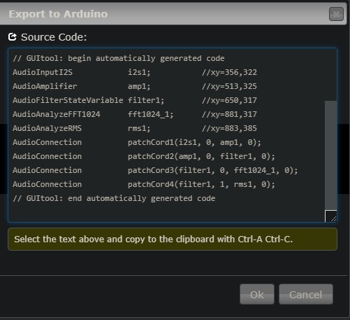
With the audio design tool, one can easily patch together a series of audio processing features, and export the proper code. The Teensy will then run this asynchronously from the main program. Note that the i2S device needs to be connected to specific pins on the teensy
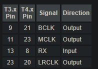
MCLK in our case is not necessary. Neither in theory is LRCLK, but it’s still connected.
As you can see there are premade analyzer functions. The RMS analyzer returns a value from 0-1 describing the short term average volume. Essentially the output of a VU meter. Just what we want.
FFT 1024 is more interesting. This feature returns a 1024 point fourier transform analysis. The specific algrorithm, FFT is known as one of the most important algorithms of all time, and is used for a wide variety of uses in computers. But in our case it can show the relative strength of frequencies in our audio stream.
The async nature of the builtin functions means that our main function simply needs to check whether new data is available every loop.
Anyway, I’m running a simulated VU tool with the Neopixels of my final project. As you can see, the mic functions.
The code can be found here