LED Vest mk4
Fourth time’s the charm
As detailed at it’s own page my last generation Led vest survived for a fairly long time, but eventually broke due to too weakly designed connectors. For the next version i set out to design an even more ruggedized version, while also implementing new functionality.
WLED.
The main new function is implementing a WLED based driver. WLED is an open source adressable LED controller software, designed to run on ESP-32 and -8266 series chips. The software can be controlled through a wide range of interfaces, with Wifi being the main one. Wifi can even be used to sync multiple instances. The LED routines are also much more impressive than my self coded attempts. Finally, many builds have sound reactivity and native I2S support. In short, WLED has a huge number of useful features for this kind of project.
For WLED to work i need to switch to ESP series of controllers.
COTS Ledstrip
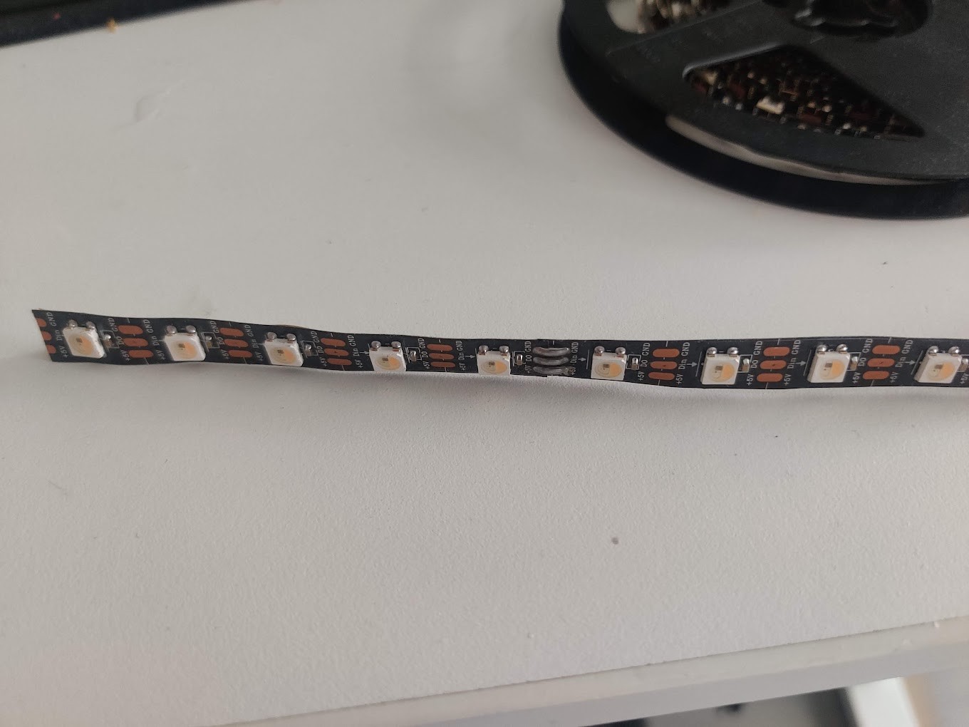
I came to the realisation that commercial 30led/m ledstrip has nearly the same spacing as my currently fully custom implementation. WRGB strip is surprisingly cheap on AliExpress, so I bought 7.5m of different kinds to experiment with home lighting.
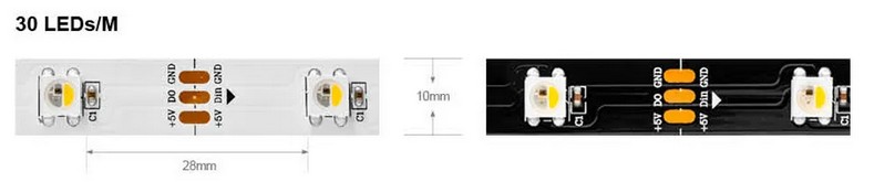
 This is 60/m strip
Using COTS leds has the main benefit of skipping all the tedious work with flexible PCBs, and also the varying quality of my soldering work. They can also be configured with a modest IP rating, which shouldn’t harm my efforts to waterproof the setup. The ledstrips also have cut points after every led. This means that I can even make the two individual leds out of ledstrip.
New connectors
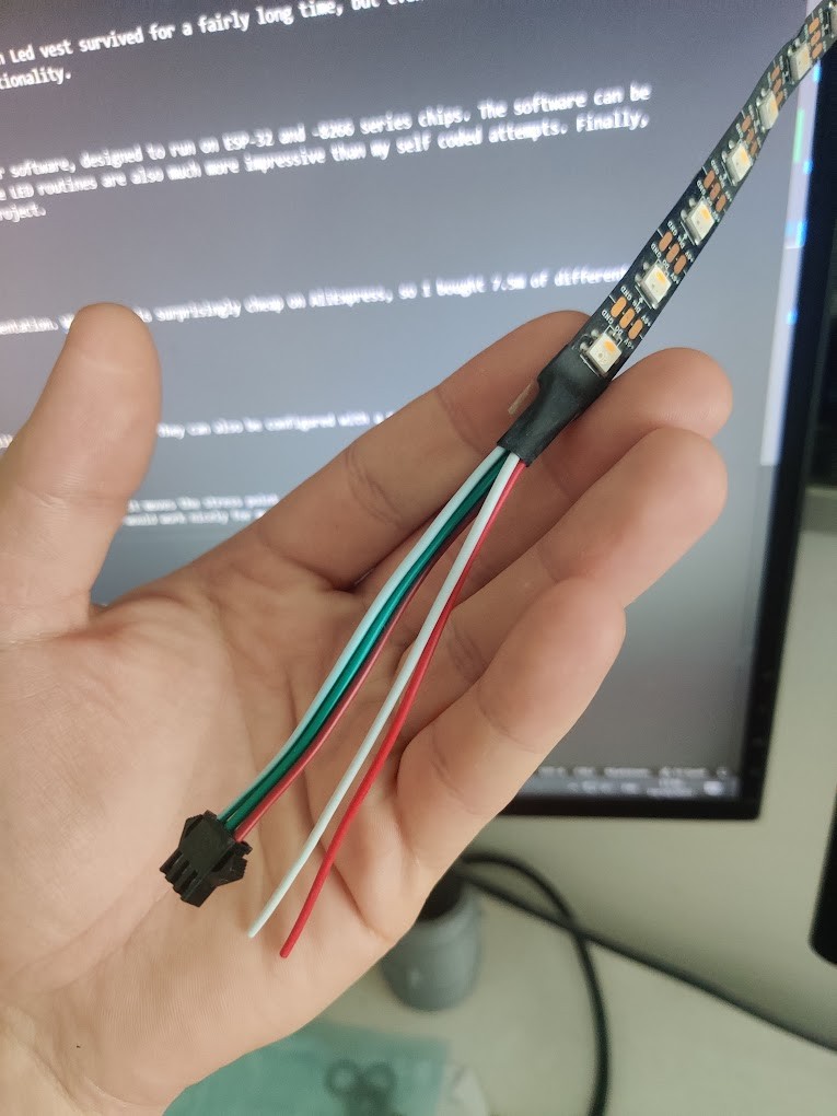
The COTS ledstrips use JST-SM pigtail connectors at the end of a short piece of wire. This is quite smart, as it moves the stress point of the connector away from the fragile flexible board. They also use a clever method of strain relief: A piece of heatshrink between the ledstrip and the wire. I thought these solutions would work nicely for my application, so I shamelessly copied them.
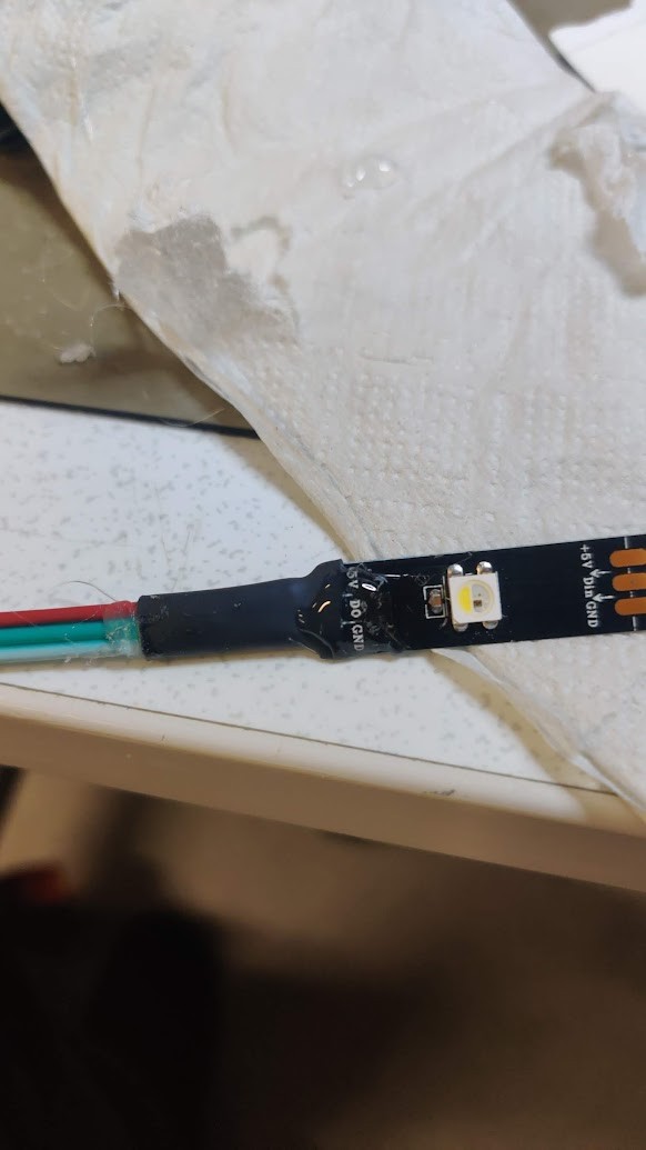
My bootleg version uses some hot glue to secure everything.
New button design
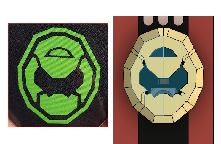 Experimental Doom theme, didn’t work out
I wanted to refresh the button design, to match all the other new features. After a bunch of drawing, and iterating in CAD I ended up on a circular design, instead of the old rectangular. As the new ledstrip is much narrower than my old full width version, The bottom support brackets can be much stronger.
I had some trouble printing the super thin bending sections on the old ledsa, so I instead designed them with V-notches at the ends to make them bendier.
I also realized that I could incorporate the strain reliefs and lower housings at the end of the LED strips.
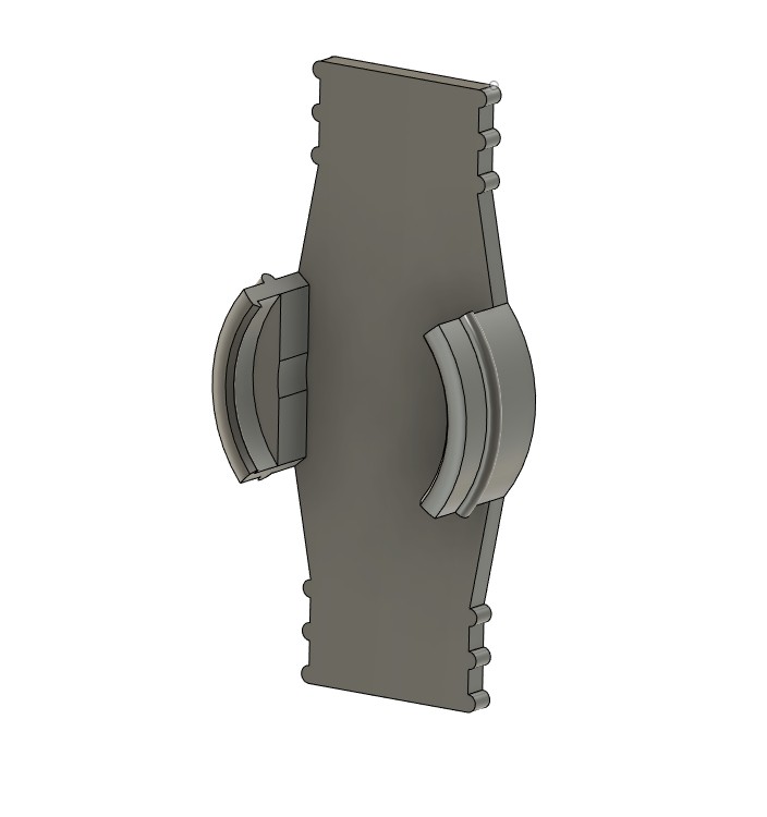
The heatshrink wraps around the ribbed part, hopefully transferring strain directly to the housing and substrate, instead of the solder joints. The main strip end connectors have a single point, and the single units have a double. The single units bottom housing has a much thicker base, as they don’t need to be flexible. As before, the final LEd in the chain will have a unused connector at the end. I have a feeling I can find a use for it, however..
Driver module
In my previous experiments with ESP’s I have used the ESP8266 based ESP-WROOM-02 chip. For WLED sound reactive, the more powerful ESP32 series are recommended.
Via fablab I got my hands on a Seeed Studio XIAO ESP32C3. This is a super compact ESP32 module, with just the right amount of I/O for this project. Perfect, I thought.
Not so fast.
The C3 variant of the ESP32 is apparently quite new, and has limited WLED support. I got stock WLED running on my unit, but was after hours of trying unable to compile a functioning sound reactive build myself. The Xiao will have to wait for tbetter compatibility
Instead, I had to source an older ESP32 from somewhere.
ESP32 D1 mini
After a visit to DeFa, I got my hands on a ESP32 D1 Mini
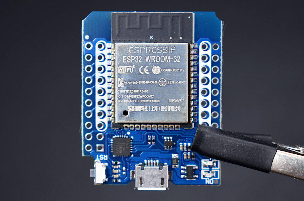
This board runs an older and fully compatible ESP32. It’s way larger than the XIAO, and uses pin headers for connectivity. After my last struggle with directly soldered pins I decided to make my board as a removable shield for the ESP, making it much easier to remove in the highly likely case I mess it up somehow.
Design
Another advantage of the D1 was that I could prototype everything on a breadboard beforehand. This ensured that The pins I wanted to use were functional, and so forth.
Like last time, I decided to run the LEDs on 3V, as this would save me the trouble of sourcing a logic level shifter. Instead, I need to install an external regulator to ensure that tle LEDs get enough current. a 1A unit should be plenty.
WLED supports a wide range of configurable physical IO. I decided on two push buttons and a potentiometer. The buttons can be bound to three presets each. From my experience, this is enough for 90% of use cases. The Pot will be used for brightness control. According to WLED documentation, the Pot will shut off the leds at max and min value. I didn’t want this to happen at max, so I put a small resistor in series to prevent the pot from ever reaching full Vref.
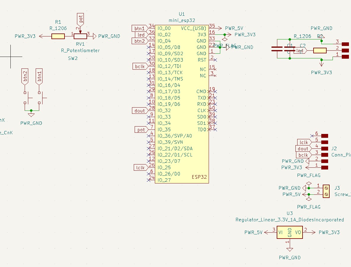
Someone has fortunately made a ready footprint in KiCAD for the D1, so that part of design was easy. Otherwise the board will have the physical IO, a screw terminal for 5V power, a simple pinout for the LEDs, and a header for the same I2s mic breakout as used before. I considered going for an SMD MEMS mic, but its still freaking tiny! If I ever end up mass producing the boards, It would be a cool option to order assembled though…
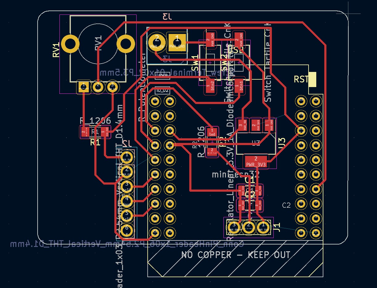 Tracing went unusually well, not a single extra jumper resistor was needed
Ready driver
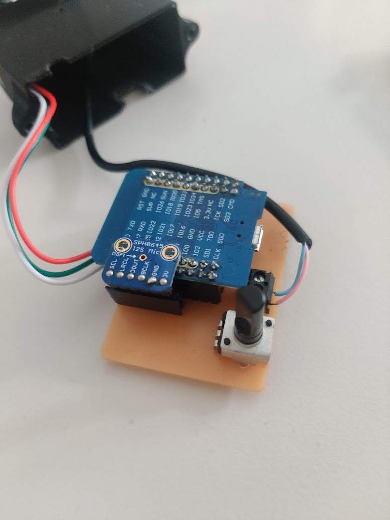
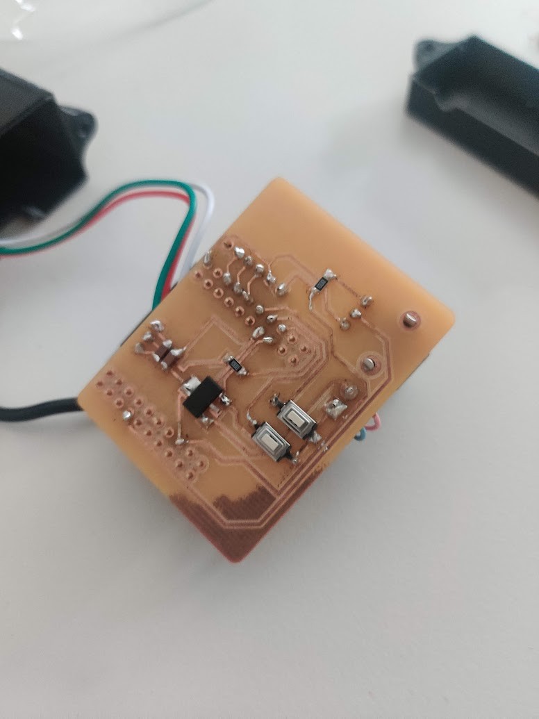
For once, the board actually came out good on the first try! The corner of the board was evidently a bit lower, as the hatching hasn’t cleared all of the copper. But this doesn’t impact function. I designed a very quick and dirty 3D printed housing for initial use. The housing has room to improve, For instance, the cables are currently not strain relieved. Especially 5V power tends to wiggle itself out. Also, the mic module is 180deg from intended. oops! fortunately the headers allow it to be simply flipped.
Assembly and result
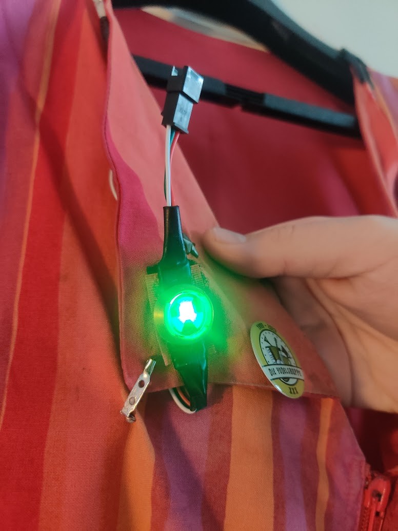
As i was on an AliEx shopping spree, I also acquired some red velcro (Impossible to find anywhere in Finland!). The LEDs are again wrapped in red vinyl, to provide the proper color and water resistance. This time neither side had ready applied adhesive. After some experiments, I ended up using textile glue, which is flexible, yet evidently strong enough.
When laser cutting the windows, I decided to put a little radiation warning trefoil in them as a decoration. This is hard to spot, looks really cool from up close.
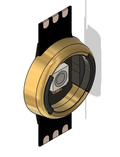
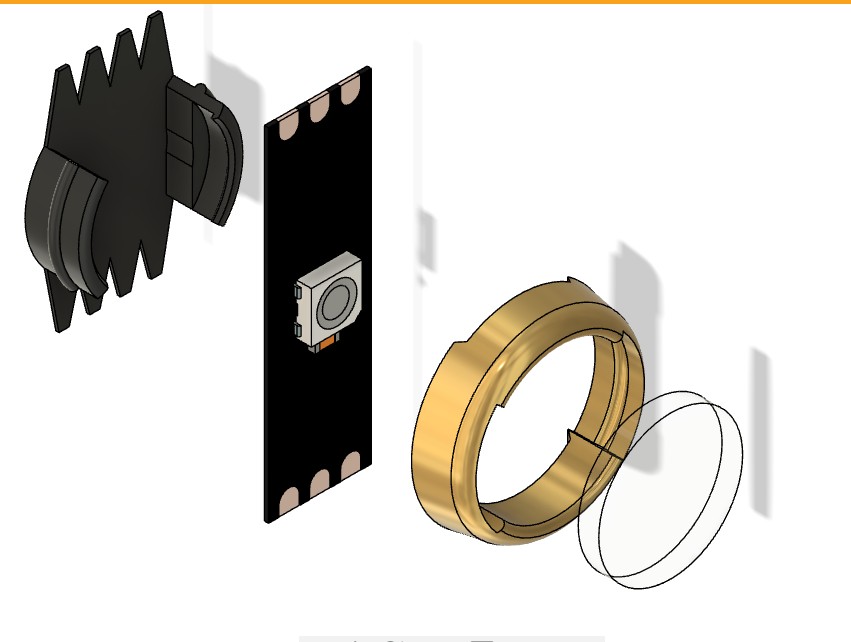
The buttons were delayed for a bit, as fablab’s Form 3 SLA printer was out of action until October. Fortunately I got the prints done, and the results were excellent. The gold colored upper shells were done with my own printer and filament. I went for a trial and error method of finding just the right size offset so that the buttons are possible to assemble, yet hold together well.
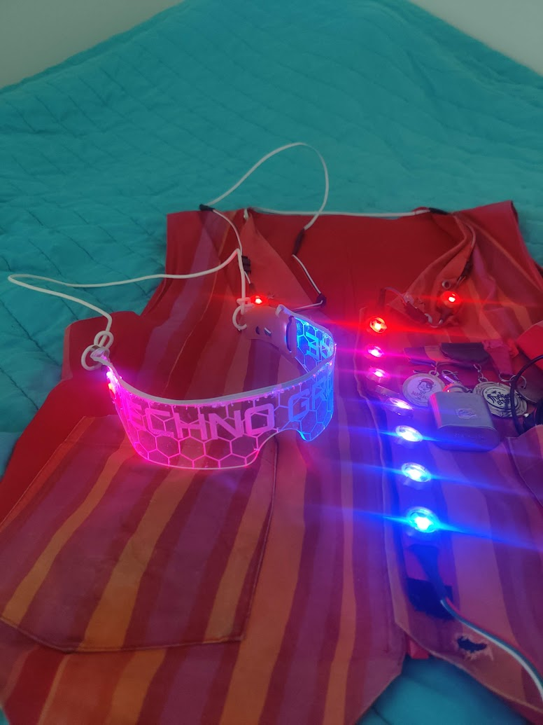
Behold, mk4!
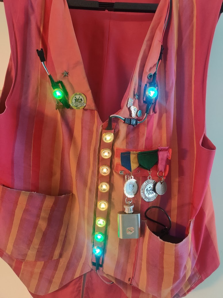
Overall the new versions definitely have the best build quality so far. Also WLED has really cool sound reactive modes!
There are still a few WIP items:
- Redo vest pass-troughs with a larger diameter so that cable connectors can be passed through them.
- Design better electronics housing, Ideally with interface to hold battery bank in position.
As for the unused connector, here is a sneak peek of what I have been working on for the last couple of months, more to come…