8. Computer controlled machining
This week revolves around CNC with the big boy Recontech machine, Fun!
Group Assignment
Our group assignment this week consisted of the introduction to our big Recontech CNC machine, introduced below. link to assignment
CAM
This time we’ll work with proper 3D CAM. Yay! As a test, I booted up Inventor and threw together a very quick planar object.
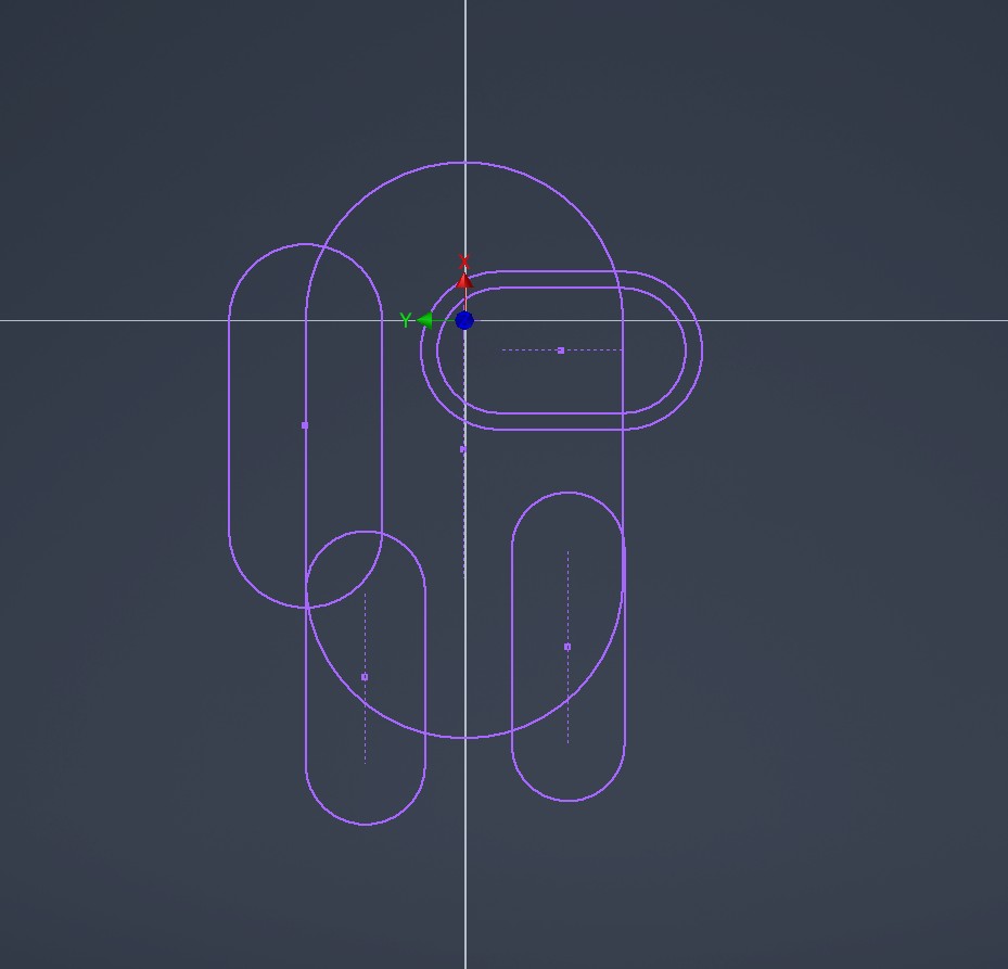

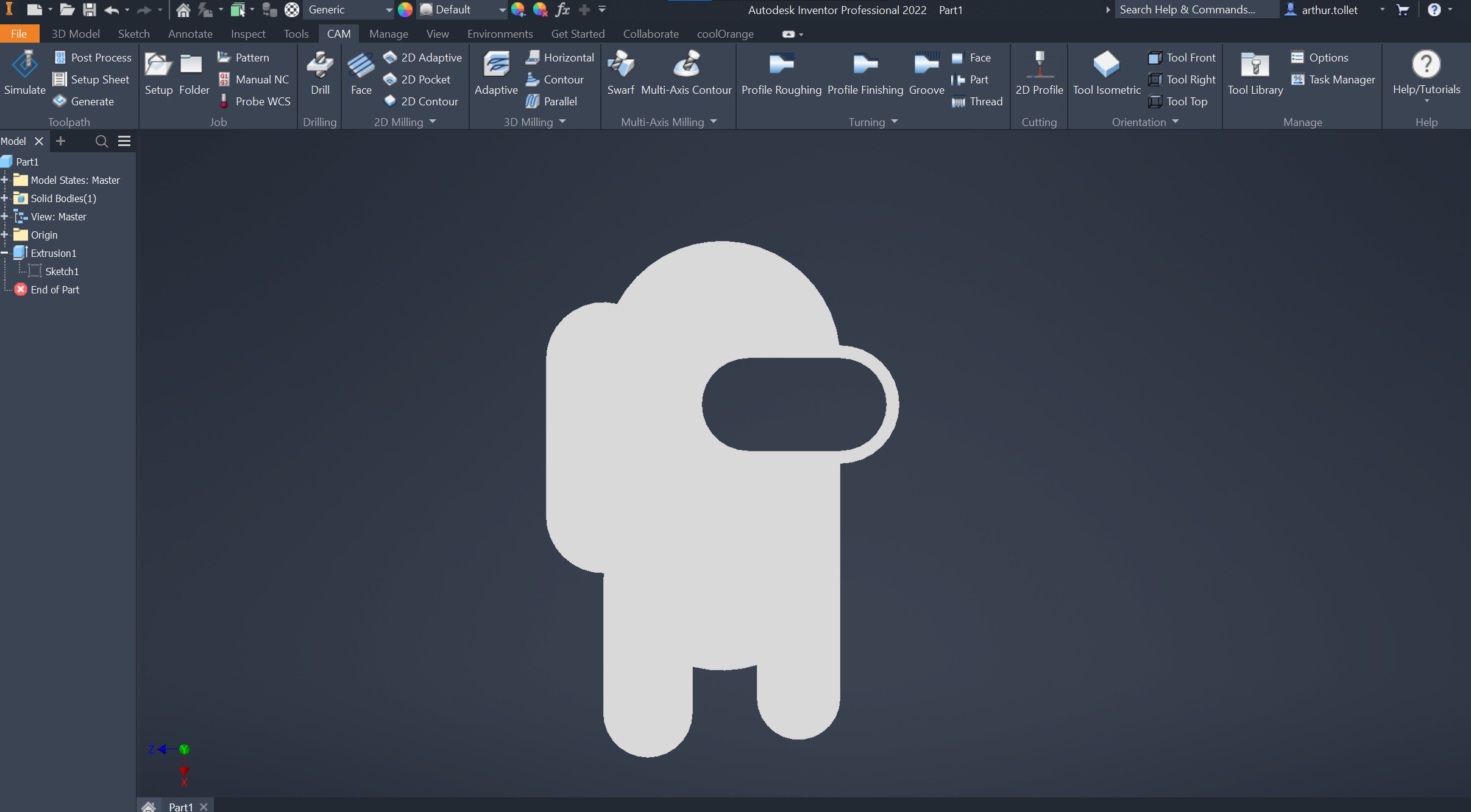
Ha Ha.
With the unusually suspicious model, we can move to the CAM environment.
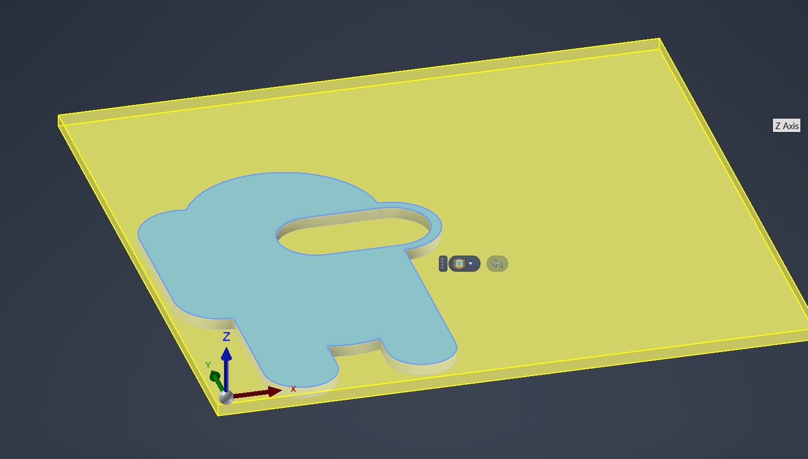
So. Let’s imagine we’d like to cut this out of a sheet of some material using the CNC. We first have to setup the stock. This is surprisingly done from the big button that says setup
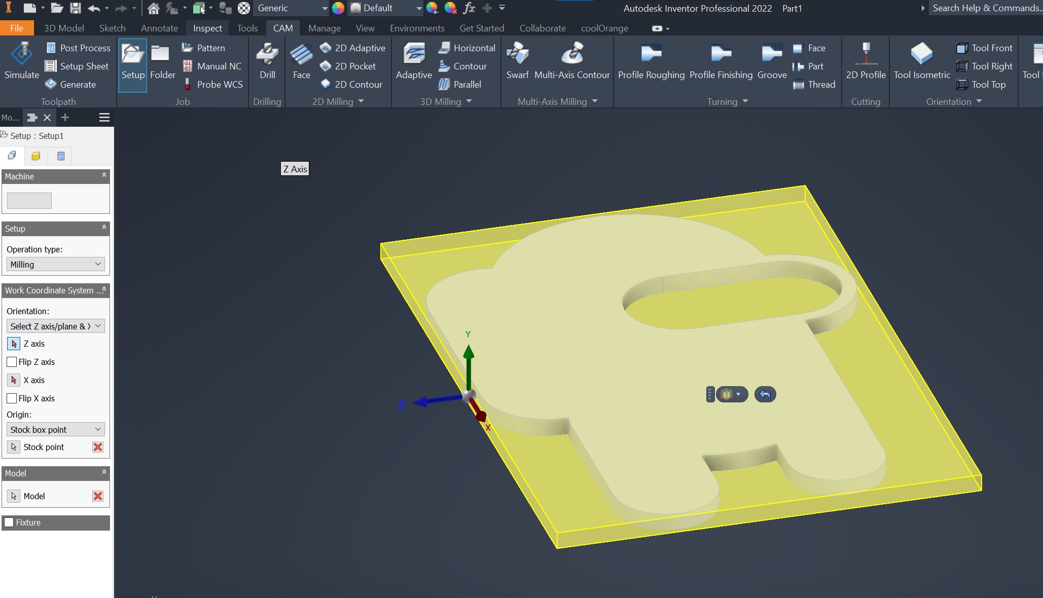
The program automatically generates a stock, and puts out coordinates in yellow. We have to change these though.
First off coordinates.

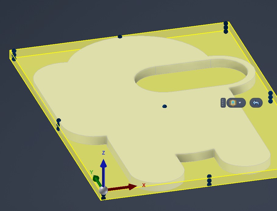
Like in 3D-printers, Z generally points upwards. So we did that, messed around with the X and Y axis, and set the origin in the corner.
Let’s say that we have a 500x500x10mm piece. We can define that from the stock menu.
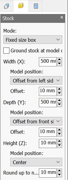
We also defined that the model is neatly in the corner, with 10mm marginal. This let’s us use the material most efficiently
We are happy with the setup, let’s move on to the actual milling.
As we only have a flat object, we’ll only need to cut it out from the stock. 2D contour is a good operation for this.
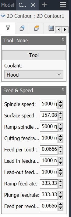
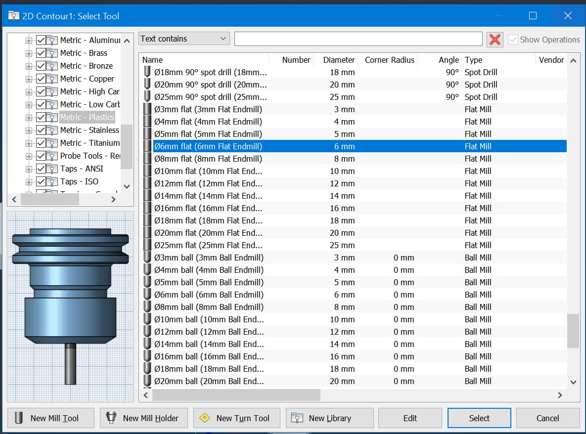
Now for tool selection, I don’t actually know what tool I’ll use, so let’s just go with a sample 6mm flat mill from Inventor
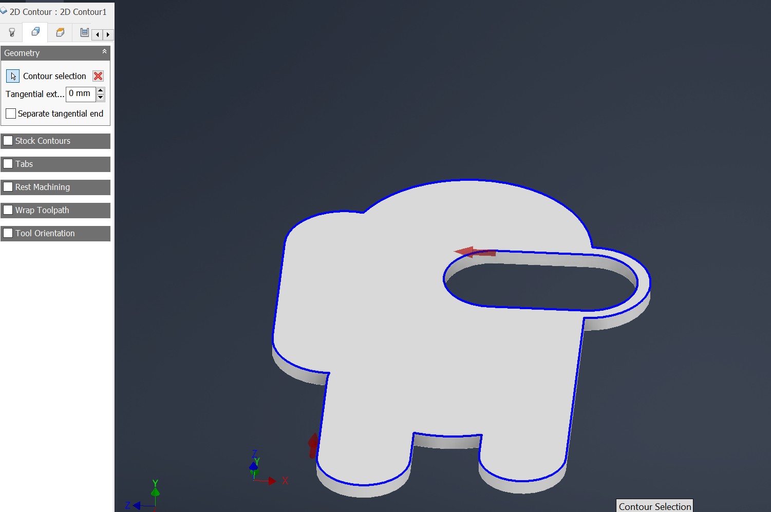
Now we simply select the contours we’d like to mill, like so:
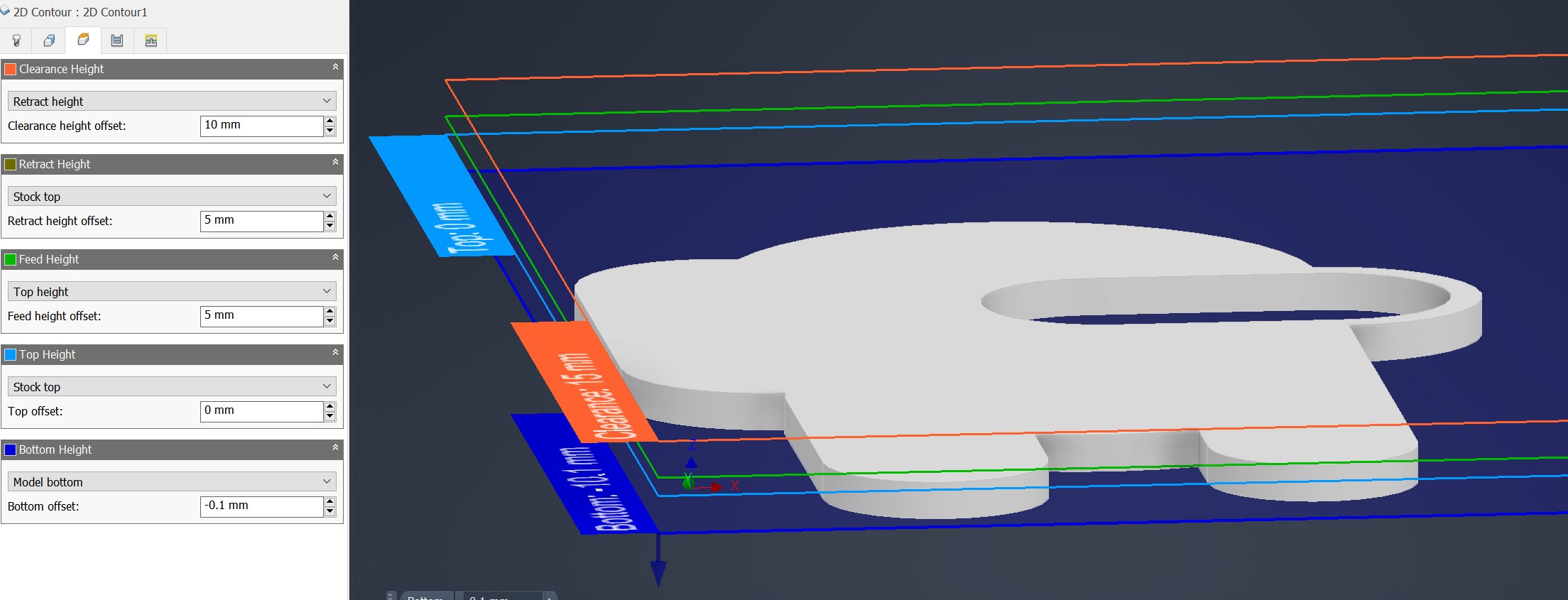
Next, from the heights tab, we can set depth. Set bottom depth to model bottom, + a small offset, perhaps 0.5mm extra. We’ll use a sacrificial bottom piece to avoid milling the CNC table…
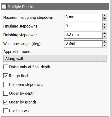
And finally, we don’t want the mill to plunge the entire way down immedeately. Let’s check multiple passes, and only let it mill 3mm at a time:
Alright! press okay to generate toolpath.
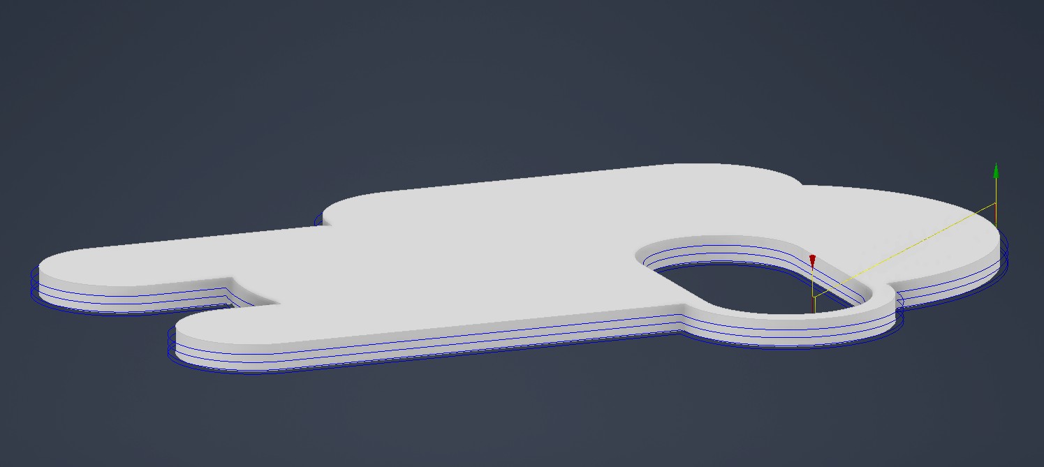
We can see what the operation looks like using simulate:
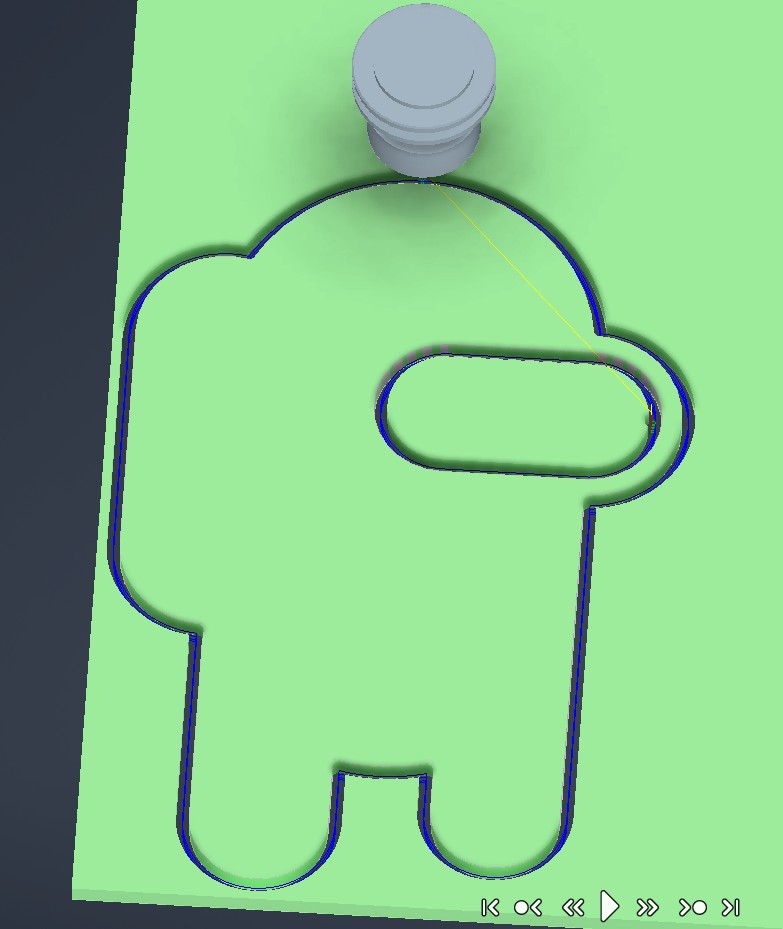
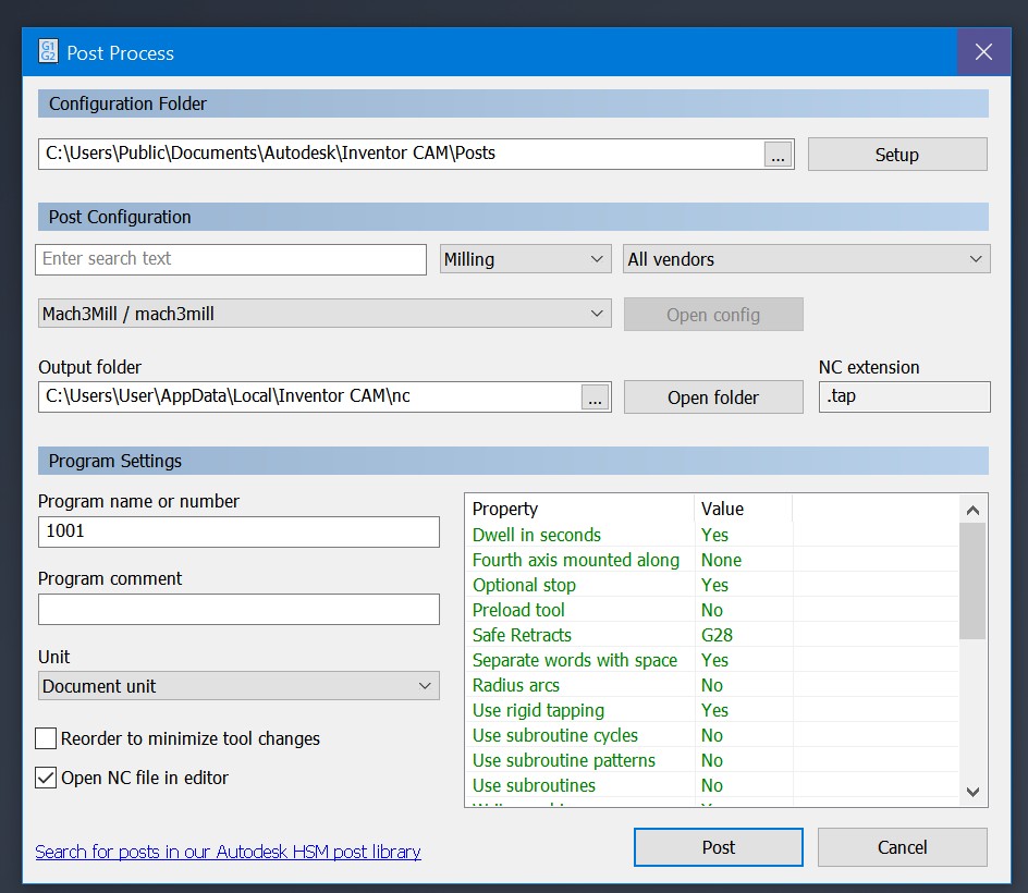
Everything looks good (except for the core concept on why we are doing this) so we can click post process to finish the program. Mach3mill is thankfully already an option without installing my own stuff.
Here is a video of the simulation in meme format. Sorry (not sorry)
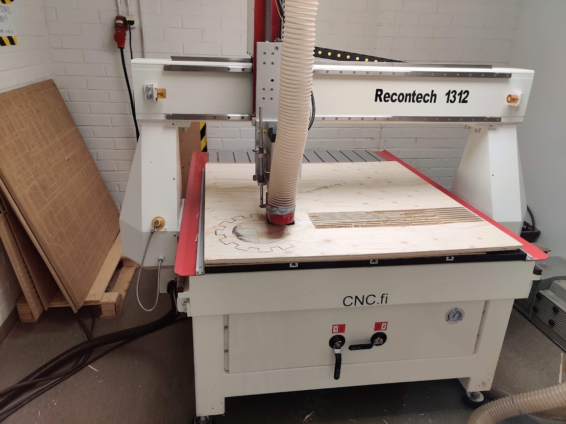
Recontech 1312
The actual mill we’ll be using is the Recontech 1312
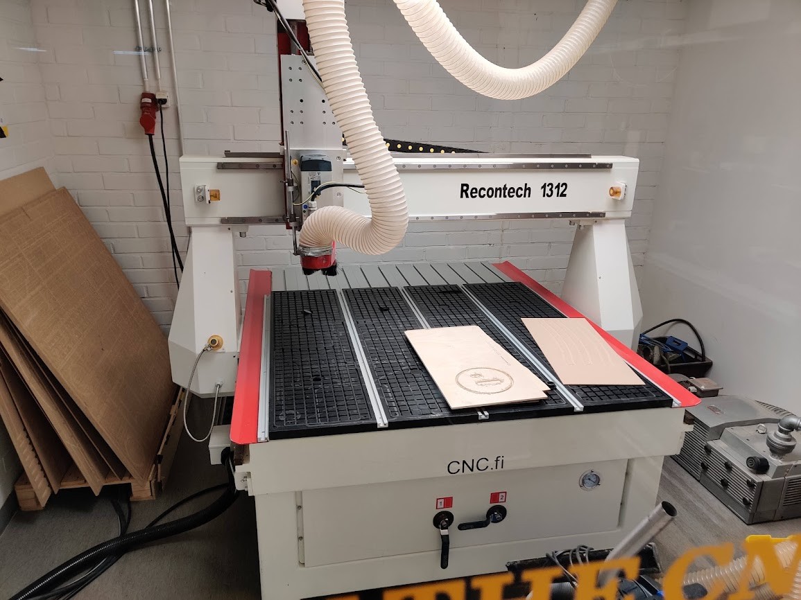
Some specs for the big boy :D
| Recontech 1312 | Specs |
|---|---|
| Work Area | 1250 * 1200 * 200mm |
| Fast travel speed | 0-25000 mm/min (416mm/s) |
| Feed rate | 0-20000mm/min (333mm/s) |
| Spindle speed | 0-18000 rpm |
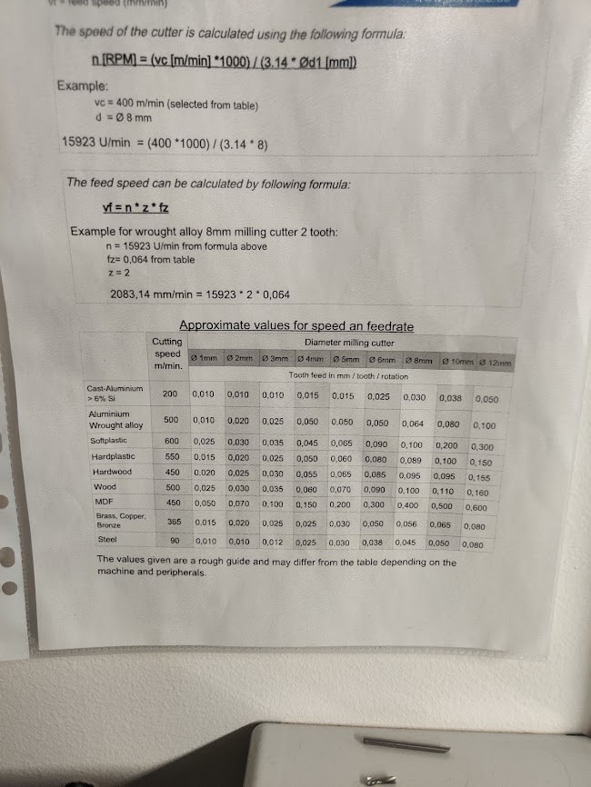
For feeds & speeds, this useful table is provided. Inventor CAM can directly tke an inout of curring speed (surface speed) to calculate feedrate.
THe recontech Is in it’s own room, which must be evacuated when the machine operates. There is a computer running mach3mill that controls everything, which coinveniently can be accessed both inside and outside the room.
Pieces can be held on in multiple ways, the primary one being a vacuum system in the table. a suction cup is essentially built by setting rubber strings and plugs on the table. A piece of MDF can be used as a sacrificial layer between the router and the table, the MDF is porous enough to let the suction through.
The tools use a pretty standard collet, and are zeroed using a Z-probe. The CNC programs are loaded as NC files. press the big green button for the fun to begin!
Bed end project
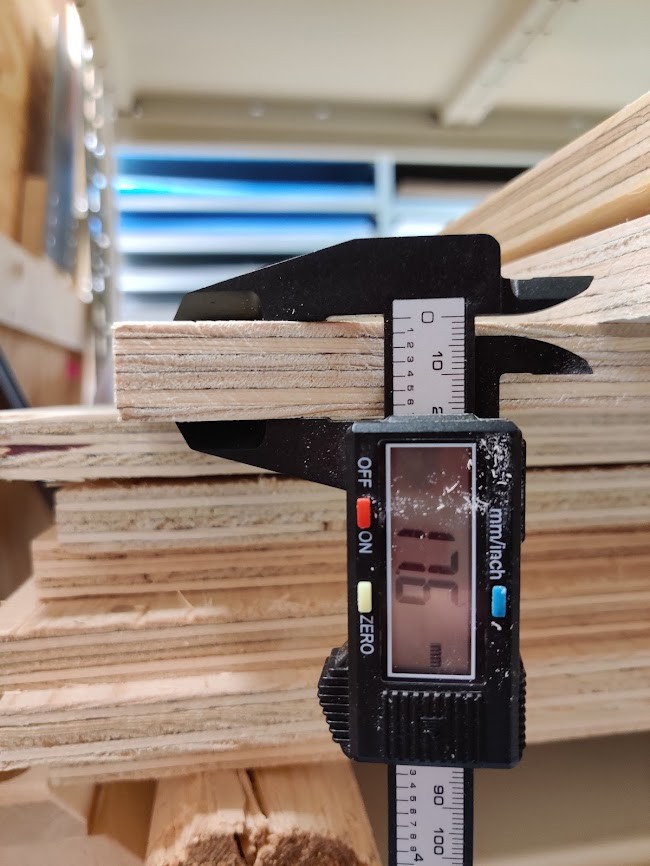
For our assignment, we each got a large-ish piece of plywood
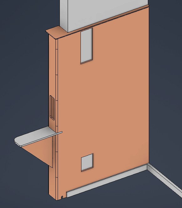
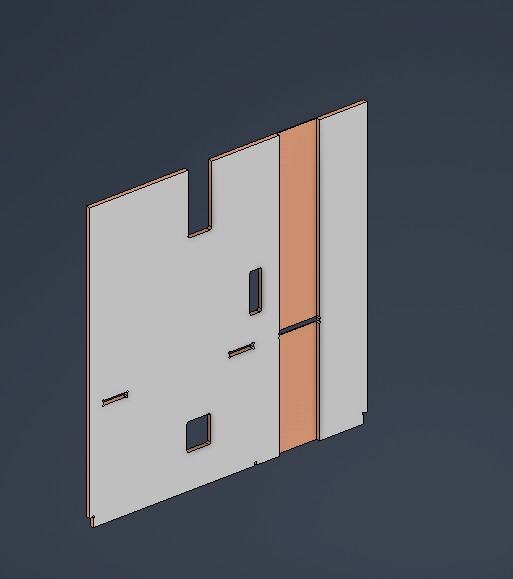
I’d like to design a bed end with a built in nightstand for my home. The plan is to have it wrap around a wall, with some features, such as a lught switch, a wall outlet and a footer board. First step was to replicate the wall in CAD
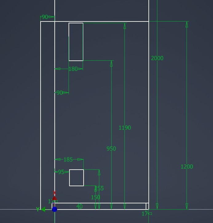
I used this basic scetch as a base for the parts:
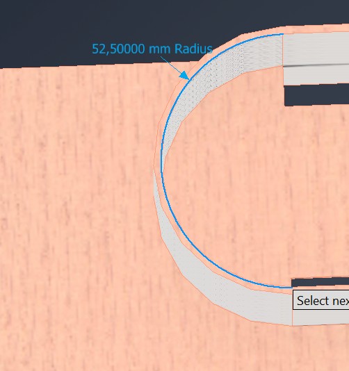
At this point I ran into a bit of a problem. I would like to avoid sharp edges in the nightstand, so I don’t hurt myself. The recontech doesn’t have a radius mill available, and 3D milling the fillets would be fairly slow.
Instead I had an idea, what about a kerf bend?
I modelled the bend as a sheetmetal object, with extrusions for full thickness, In this way, I could use sheetmetal unbend to get the flat pattern.
We then move to CAD. At this point I needed to calculate the material i need to remove for the kerf bend to bend correctly.
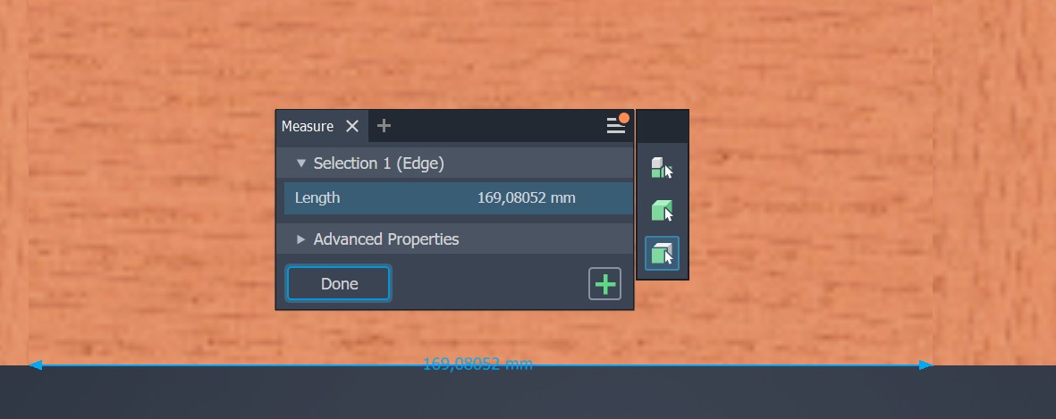

It turns out that there are online kerf bend calculators I could have used. Oh well :)
Next step is the CAM setup. I first tried to mill the flexure with the pockets modelled as physical features. apparently however, pocket and contour programs wouldn’t work with this. line trace mode also wasn’t working that well.
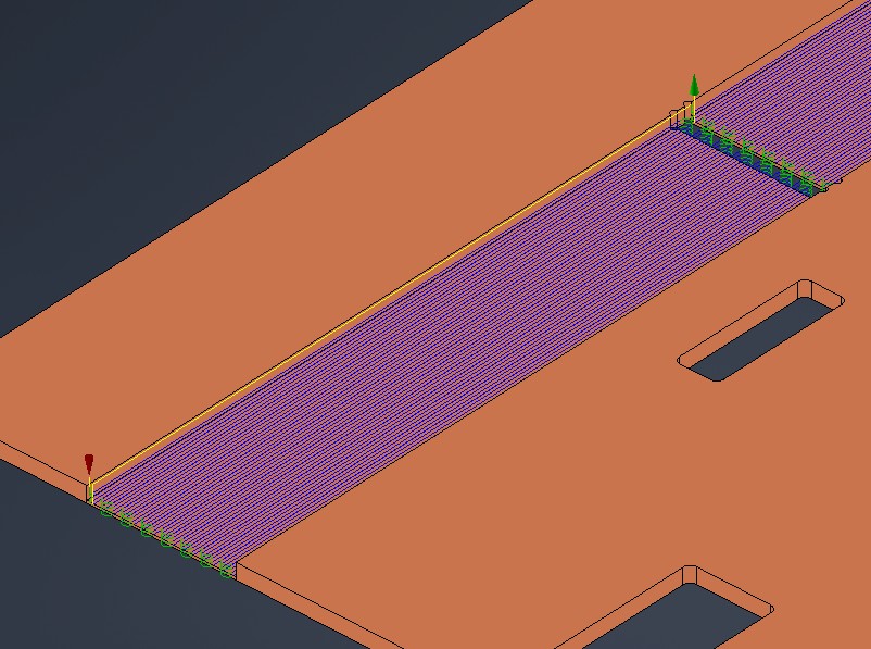
Then i discovered that face milling has a stepover option.
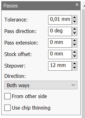
Usually, the stepover value is slightly less than the tool thickness, but setting it to more I easily and efficiently got a good toolpath for the kerf cut operation.
The rest of the toolpaths are a combination of multi level conture and 3D milling. I initially tried some test cuts.
I decided to cut a couple of test pieces. The results were…interesting.
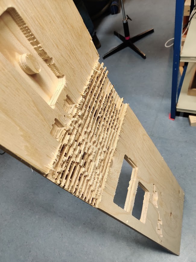
First off, an upcut mill really shreds the top layers, in my bedend, these in principle are hidden, but this still looks really nasty.
Also the wood didn’t bend well enough. I tried running hot water over it to soften the lignin, but that didn’t work as well as hoped either. The wood is quite low quality (probably spruce) with a lot of branches and such, which degrades bend performance.
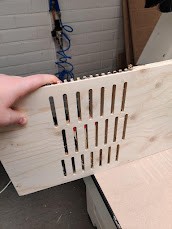
I also tried even more material removal, but this design straight up broke in half.
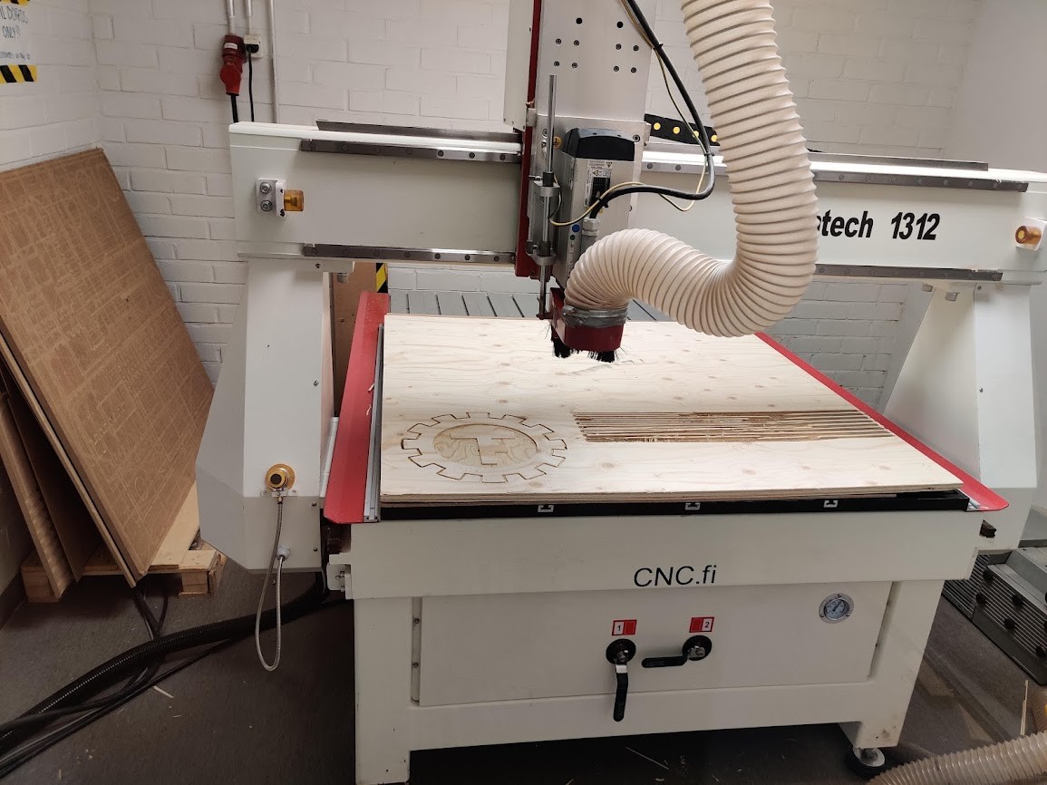
I decided to try a full scale piece, and ran into more trouble. The wood is quite warped, and had trouble adhering to the suction. During milling it then broke off, making the piece unsuitable for the bedend.
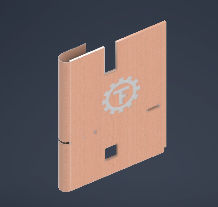
It was quite late at this point, and I really wanted to get something done, so I thought up an alternative plan:
I decided to make our student association logo from the remaining material. This was a very simple CAM process, with a 2D pocket and contour. I maked sure to use the downcut mill this time first.
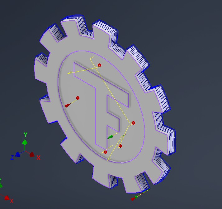
For the last step of the contour milling i switched to upcut, to ensure that the bottom looks as nice. Here is the end result:
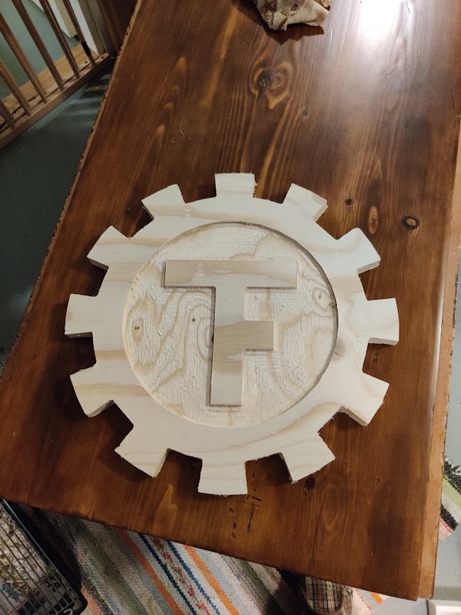
You really can see the difference between upcut and downcut..
Design files for this week can be found here