13. Sensors & Input devices
This week was about teaching our microcontrollers to react to the the environment for fun & profit
For this week i decided to investigate how to get an audio response for my LED vest project
Our group assignment can be found here
Research
I first investigated what mics we have available at fablab. It turns out there are two options
The first one is an electret mic. An extremely simple analog device. The electret bassically works as a variable capacitor, creating a weak analog signal from the audio. The simplicity also means it needs an external preamp.
The other option is much more fancy, a digital MEMS mic with built in microcontroller. This puppy reads audio and outputs a full i2s signal. These are also available as both breakout board versions, and even tiny SMD components. Amazing.
At first, I was very interested in the MEMS mic, especially since it hs so many features built in. However, the MEMS only runs on 3.3V. As my system will be 5V, this is a problem.
While I could have a separate 3.3V bus, I don’t need a veryu good quality audio signal to essentially simply read it’s volume. Thus, the electret mic is better for my purposes.
Op-amp
For the analog mic, I will need a pre-amp to amplify the signal before feeding it to the microcontroller. Apparently, an operational amplifier or op amp is the bees knees for this kind of work.
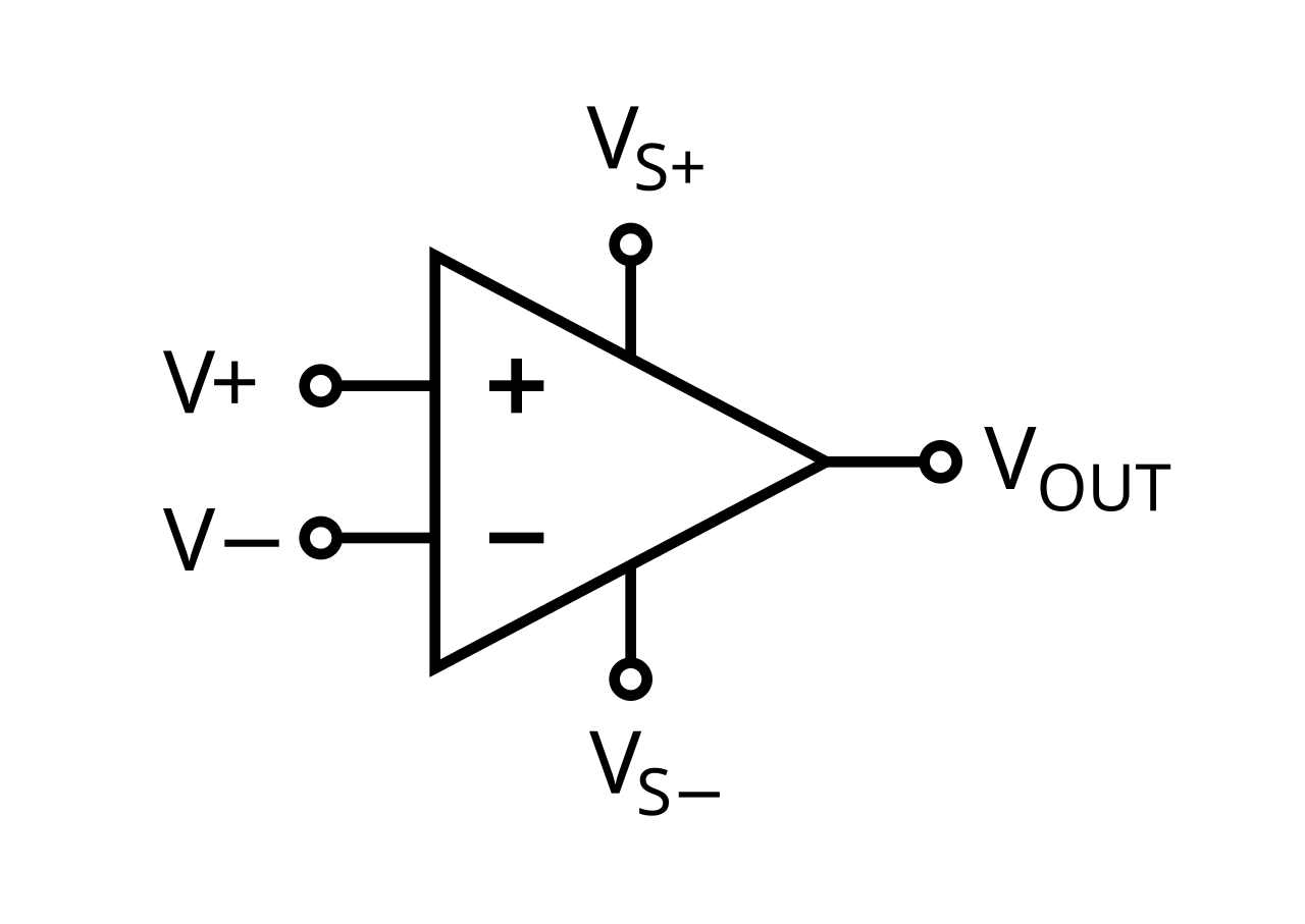
Allegedly, the op amp is amazing and used everywhere. I’ve never really understood the wiring of them though, they need a fair amount of external components to work.
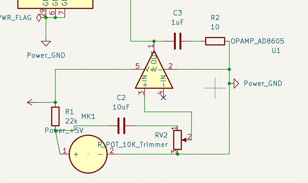
I messed around in KiCAD using some circuit examples I found online. I’m still a bit confused about what i’m doing though.
Kris hinted that there is an electret opamp example board! yay!
From this I can develop my own flavor variant.
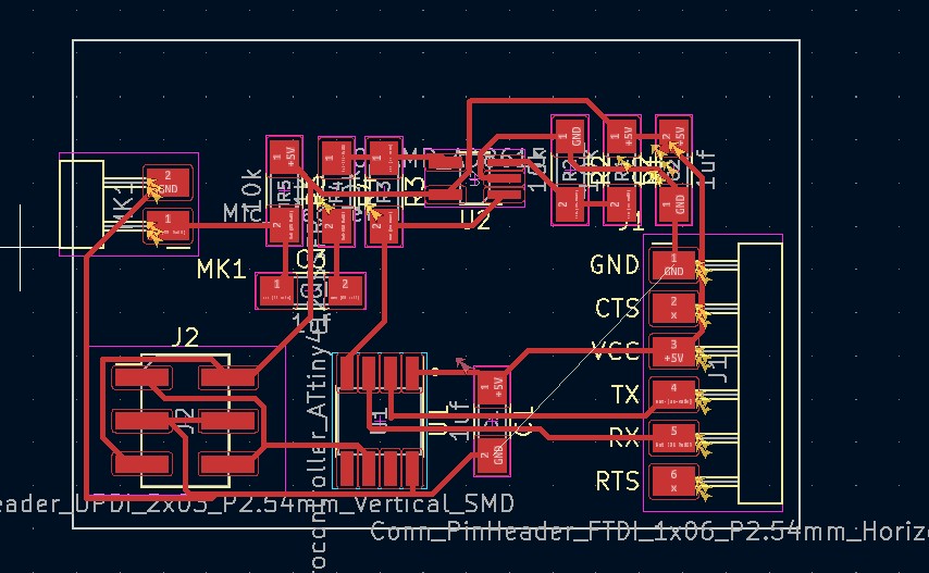
First step will be reverse engineering the example board. I will make one from scratch in KiCAD, since I want to integrate the entire circuit later to something else.
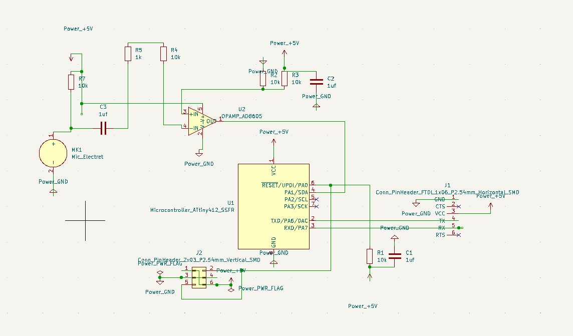
I made some changes to my board The original board didn’t use UPDI, so i switched to using that. I’m somewhat unsure if the components match, but they’re hopefully ok.
The problem here is that as far as I can find there is no documentation on the board…That’s unfortunate. For instance, there are two connections between the microcontroller and the opamp. One is from the opamp output, so I will assume thats the audio in, but the other one I have no idea anout. I’ll connect it to a PWM equipped outlet and well see…
Last ground lead making my life hard… WIll probs just solder in a jumper!
After finishing that board, I instead decided tyo make an Arduino shield to begin with. Just to reeduce risk. The shield also has two pots and a button to work as controls for the arduino.
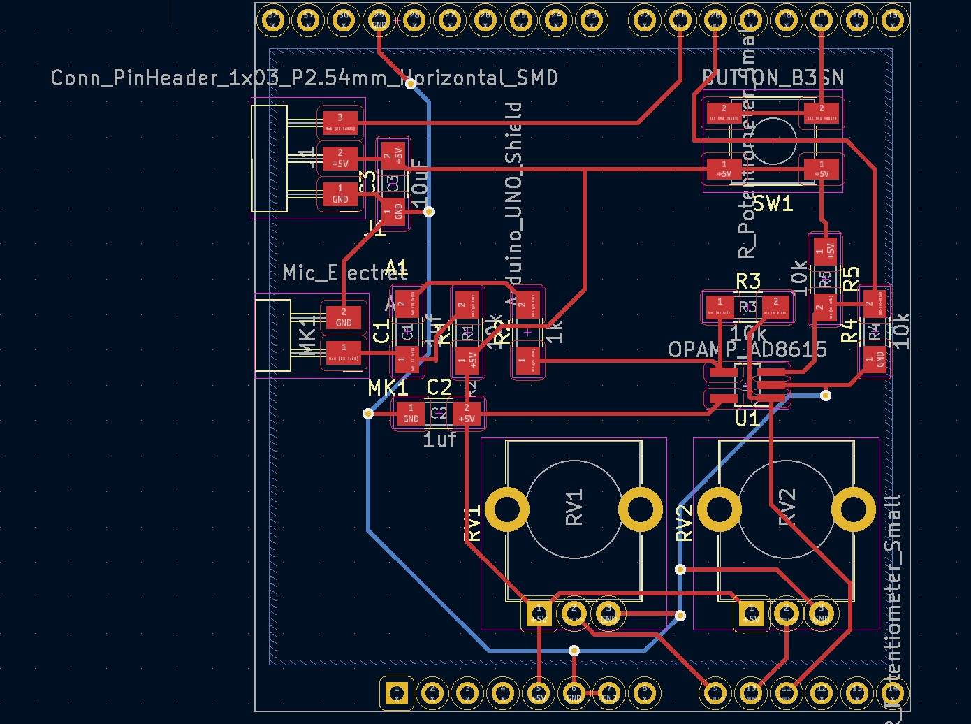
As previously, the traces just wouldn’t work out in one plane. I wonder if there is an easy way to add 0 Ohm resistors as jumpers…
What I decided to do instead was make a one and a half sided board. This means I use the bottom side fo the board as a ground plane, with vias. Getting the ground traces on the other side makes my life much easier.
Or so i thought
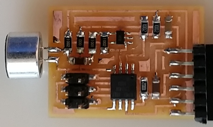
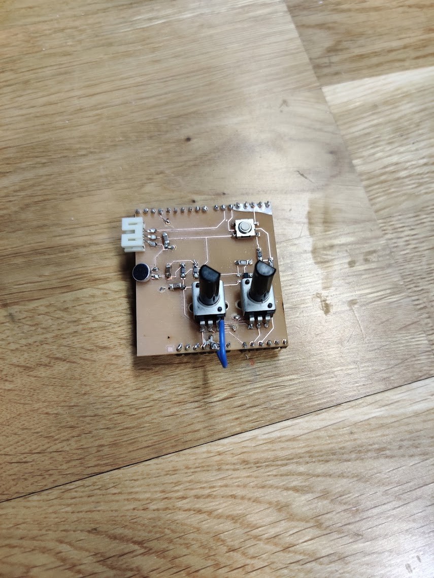
Board milling went alright, but there were some issues at fablab. For instance, someone has broken the via press! I had to use The variant for the larger vias, so the via connections were quite unreliable. Lot of soldering and a jumper used to compensate.
Soldering the opamp turned out to be a pain in the a**. Especially since early on, a tgrace decided to yeet itself forom the board. A lot of suffering and burned fingers later, I got it attached.
Testing
I wrote a really simple test program again.
//#include <Adafruit_NeoPixel.h>

#define BUTTON_PIN   2

#define PIXEL_PIN   6  // Digital IO pin connected to the NeoPixels.

#define OPAMP_PIN   5

#define PIXEL_COUNT 10  // Number of NeoPixels

#define POTPIN1       A0

#define POTPIN2       A1

#define AUDPIN       A2

void setup() {
Serial.begin(9600);
pinMode(BUTTON_PIN, INPUT_PULLUP);
pinMode(POTPIN1, INPUT);
pinMode(POTPIN2, INPUT);
pinMode(AUDPIN, INPUT_PULLUP);
pinMode(OPAMP_PIN, INPUT_PULLUP);
//Serial.println("Pot1 Pot2 AUD");

// put your setup code here, to run once:

}

void loop() {
int y1 = analogRead(POTPIN1);
int y2 = analogRead(POTPIN2);
int y3 = analogRead(AUDPIN);

analogWrite(OPAMP_PIN, y1 / 4);

//Serial.print(y1);
//Serial.print(" "); // a space ' ' or  tab '\t' character is printed between the two values.
//Serial.print(y2);
//Serial.print(" "); // a space ' ' or  tab '\t' character is printed between the two values.
Serial.println(abs(y3));

// put your main code here, to run repeatedly:

}
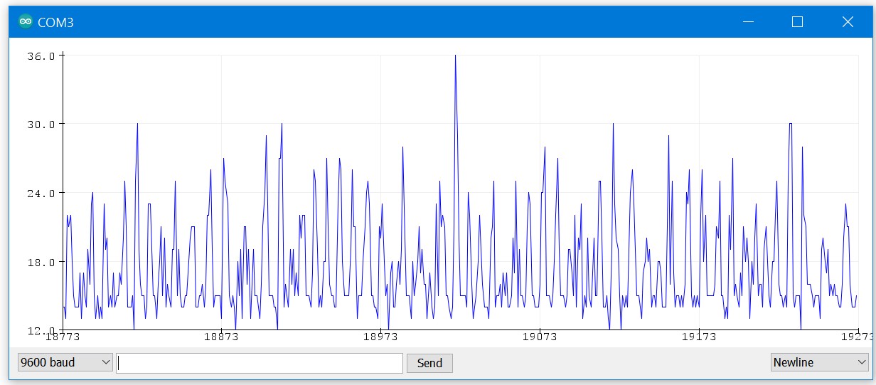
There are good news and bad news. The mic is working. As in it does pick up sound. The bad news, is that it does really poorly. I doubt that the opamp is actually working. Bottom line is, the signal is unusable :(
Might have to rethink that digital mic again…
Design files can be found here