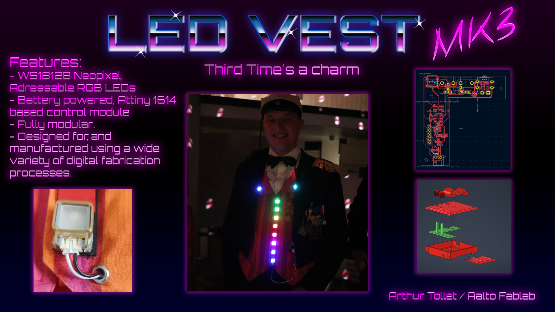
LED Vest mk3. Fab Academy final project
Video Presentation Woo!
Background
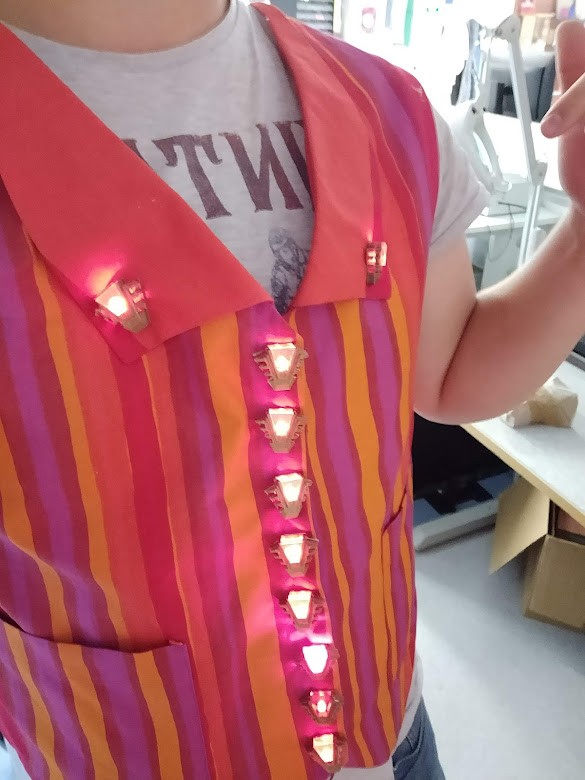
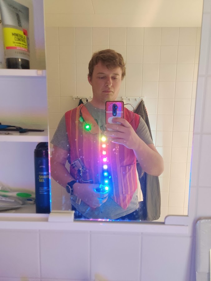
I have been experimenting with incorporating LED buttons to my student band uniform. My current solution uses silver laced conductive sewing thread. That solution however is ill suited for the hight-wear environment, and breaks all the time. While the thread is fairly easy to fix, it’s clearly not a good solution. Also, the thread has such a high resistance that the LEDs are fairly dim., and the wiring needs to resemble a ring circuit to ensure steady glow.
A flexible circuit could be the solution. Perhaps I could make a substrate that attaches to the front of the uniform with velcro. That way, the entire electronics module could be removed for maintenance or upgrade. In general, modularity is never bad.
With the sewing thread i had a hard enough time just trying to keep the V and GND leads from shorting. With the substrate however i could not only skip that problem, but perhaps integrate data lines for addressable LEDs.
Idea
I drafted two general ideas using diagrams.net:
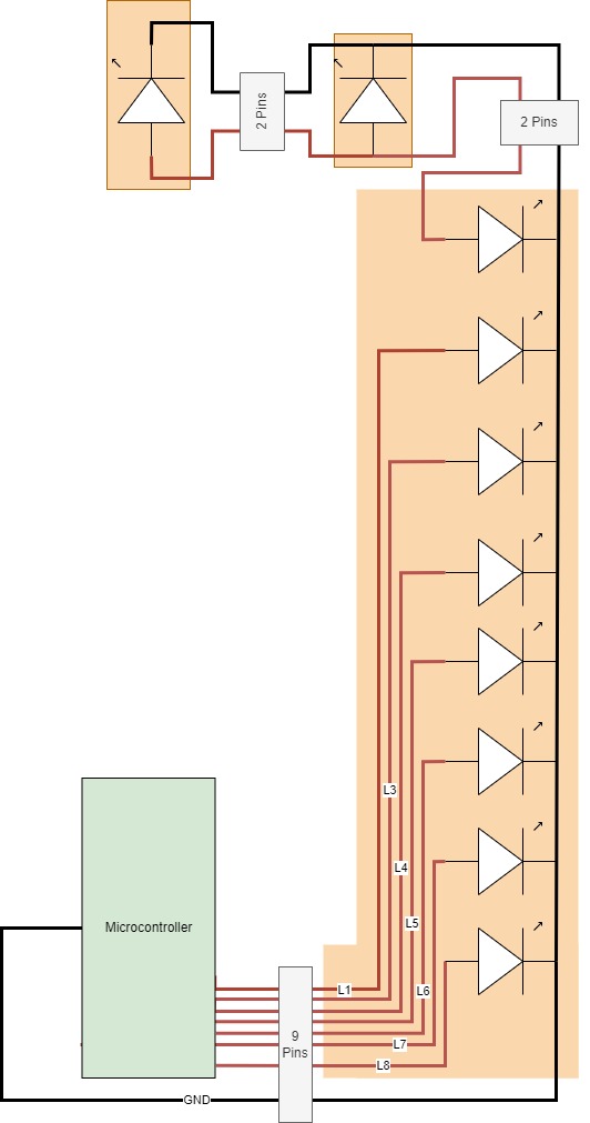
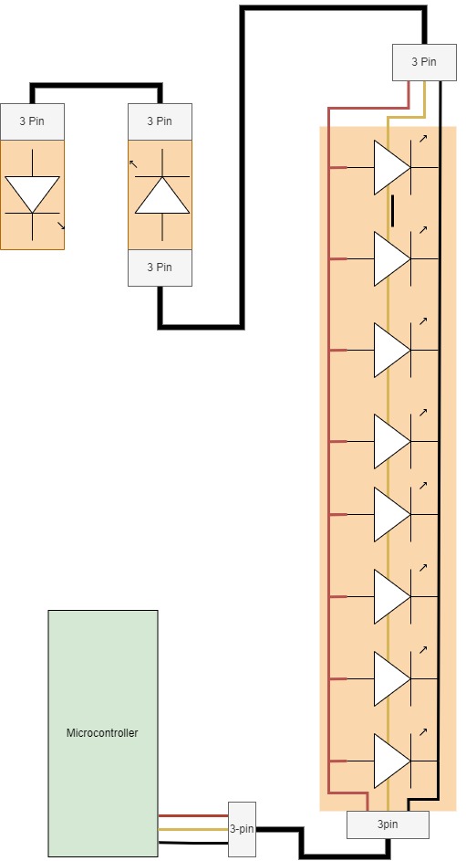
The first has parallel controlled leds, whereas the other uses an unified data line for them all.
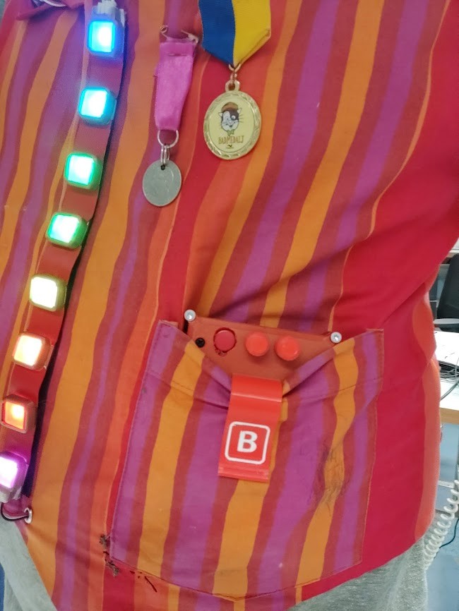
As you can see from the previous vest image, the lights, 10 in total, are arranged in a line of 8, and two individuals. The line would be a single flexible substrate, whereas the individuals would need another solution. Ideally, those too are detachable.
The vest opens from the front, so the connector to the right upper led needs to go behind the back.
There are advantages and disadvantages to both solutions. Addressable leds are apparently quite cheap these days, so i’m inclined to go for that approach. I wonder if the LEDs should be in parallel or series?
Neopixel
Neopixels are adressable LEDs. They are built around the WS2812B control chip.
These LEDs come in a bunch of sizes, even a 5mm throughhole type. I borrowed some of these from Aalto design factory (Ty defa <3), and built a prototype circuit on a breadboard.
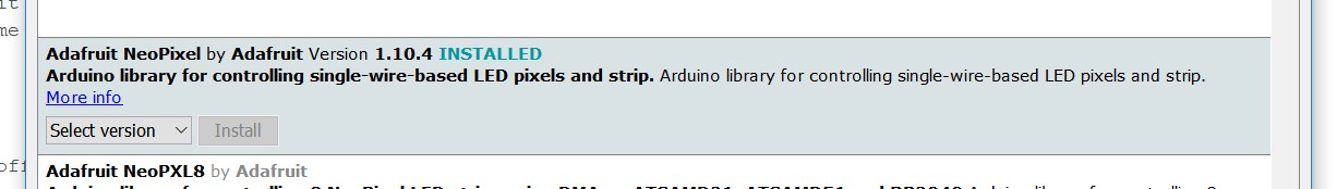
Getting the neopixels working was very simple. I just had to install a neopixel library through the Arduino IDE library manager
I modified my own test program from one of the included examples. The included one simply cycled through 8 alternative light cycles using a button. I modified it by reducing modes to 3, making them loop forever, and using interrupt logic on the button to interrupt said infinite loops. I also added a potentiometer. In the first two modes it is used to set LED brightness (Although one of them is LEDs off, so brightness doesn’t really apply there). In the final mode, Rainbow, the potentiometer is used to set animation speed. In the final control unit I’d like to have this control setup as well, one button and one potentiometer.
Below is my code.
  #include <Adafruit_NeoPixel.h>
  #ifdef __AVR__
  #include <avr/power.h> // Required for 16 MHz Adafruit Trinket
  #endif

  // Digital IO pin connected to the button. This will be driven with a
  // pull-up resistor so the switch pulls the pin to ground momentarily.
  // On a high -> low transition the button press logic will execute.
  #define BUTTON_PIN   2

  #define PIXEL_PIN    6  // Digital IO pin connected to the NeoPixels.

  #define PIXEL_COUNT 10  // Number of NeoPixels

  #define POTPIN       A0

  volatile bool interrupt;

  // Declare our NeoPixel strip object:
  Adafruit_NeoPixel strip(PIXEL_COUNT, PIXEL_PIN, NEO_RGB + NEO_KHZ800);
  // Argument 1 = Number of pixels in NeoPixel strip
  // Argument 2 = Arduino pin number (most are valid)
  // Argument 3 = Pixel type flags, add together as needed:
  //   NEO_KHZ800  800 KHz bitstream (most NeoPixel products w/WS2812 LEDs)
  //   NEO_KHZ400  400 KHz (classic 'v1' (not v2) FLORA pixels, WS2811 drivers)
  //   NEO_GRB     Pixels are wired for GRB bitstream (most NeoPixel products)
  //   NEO_RGB     Pixels are wired for RGB bitstream (v1 FLORA pixels, not v2)
  //   NEO_RGBW    Pixels are wired for RGBW bitstream (NeoPixel RGBW products)

  int     mode     = 0;    // Currently-active animation mode, 0-9

  void setup() {
    pinMode(BUTTON_PIN, INPUT_PULLUP);
    strip.begin(); // Initialize NeoPixel strip object (REQUIRED)
    strip.show();  // Initialize all pixels to 'off'
    attachInterrupt(digitalPinToInterrupt(BUTTON_PIN), intf, CHANGE);
  }

  void loop() {
    interrupt = false;
    if(++mode > 2) mode = 0; // Advance to next mode, wrap around after #2
    switch(mode) {           // Start the new animation...
      case 0:
        colorWipe(strip.Color(  0,   0,   0), 50);    // Black/off
        break;
      case 1:
        colorWipe(strip.Color(255,   0,   0), 50);    // Red
        break;
      case 2:
        rainbow(10);
        break;
    }
  }

  // Fill strip pixels one after another with a color. Strip is NOT cleared
  // first; anything there will be covered pixel by pixel. Pass in color
  // (as a single 'packed' 32-bit value, which you can get by calling
  // strip.Color(red, green, blue) as shown in the loop() function above),
  // and a delay time (in milliseconds) between pixels.
  void colorWipe(uint32_t color, int wait) {
    while(!interrupt){  //while button isn't pressed

      for(int i=0; i<strip.numPixels(); i++) { // For each pixel in strip...
        strip.setBrightness(map(analogRead(POTPIN), 0, 1023, 0, 255)); //set brightness from 0-255, depending on the 10-bit POTPIN value
        strip.setPixelColor(i, color);         //  Set pixel's color (in RAM)
        strip.show();                          //  Update strip to match
        delay(wait);                           //  Pause for a moment
      }
    }

  }

  // Rainbow cycle along whole strip. Pass delay time (in ms) between frames.
  void rainbow(int wait) {
    // Color wheel has a range of 65536 but it's OK if we roll over, so
    // just count from 0 to 3*65536. Adding 256 to firstPixelHue each time
    // means we'll make 3*65536/256 = 768 passes through this outer loop:
    while(!interrupt){
      for(long firstPixelHue = 0; firstPixelHue < 65536; firstPixelHue += 256) {
        wait = map(analogRead(POTPIN), 0, 1023, 50, 1);  //set animation speed from 100-1ms, depending on 10-bit POTPIN value
        for(int i=0; i<strip.numPixels(); i++) { // For each pixel in strip...
          // Offset pixel hue by an amount to make one full revolution of the
          // color wheel (range of 65536) along the length of the strip
          // (strip.numPixels() steps):
          int pixelHue = firstPixelHue + (i * 65536L / strip.numPixels());
          // strip.ColorHSV() can take 1 or 3 arguments: a hue (0 to 65535) or
          // optionally add saturation and value (brightness) (each 0 to 255).
          // Here we're using just the single-argument hue variant. The result
          // is passed through strip.gamma32() to provide 'truer' colors
          // before assigning to each pixel:
          strip.setPixelColor(i, strip.gamma32(strip.ColorHSV(pixelHue)));
        }
        strip.show(); // Update strip with new contents
        delay(wait);  // Pause for a moment
      }
    }

  }

  void intf() {
    interrupt = true; //Interrupt function, set interrupt flag to true
  }
System overview
The final system will consist of 4 components:
- Pocket mounted control box with battery
- Velcro-mounted flexible PCB with 8 Leds in-line
- Two individual PCB mounted LEDs. With velcro or riveted buttons
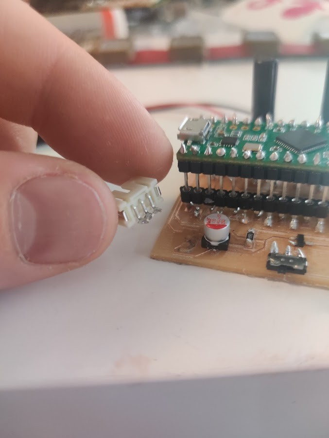
Everything will be connected with 3-pin JST connectors.
I had the opportunity to order LEDs, so I got some 5050 package SMD ones. THese should be the smallest possible package. The plan is to directly solder these to the flexible substrate.
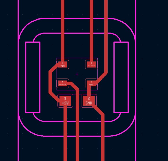
Circuit design
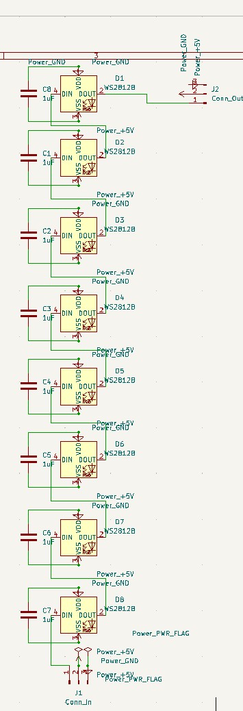
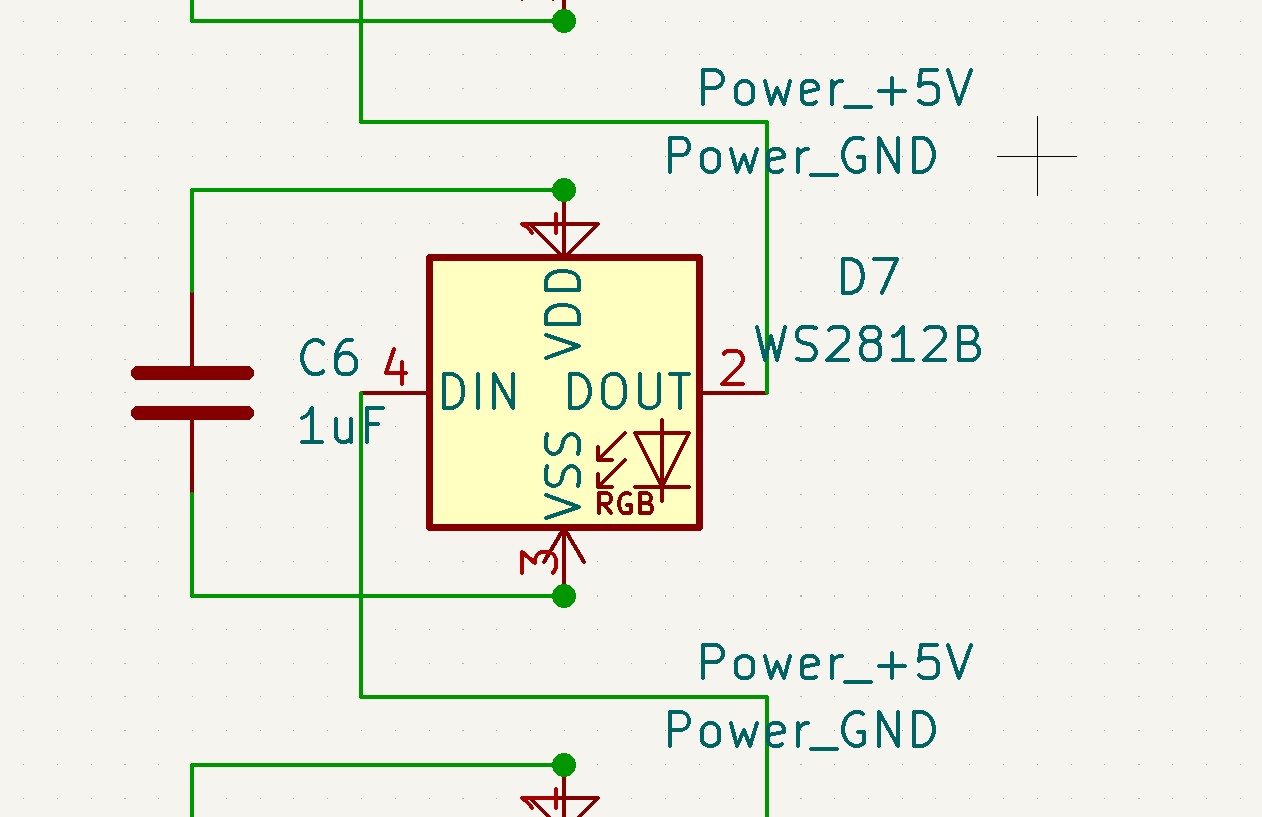
Circuit design of the flexible strip is quite simple. The LEDs are connected to +5V and GND, and chained on the data line, furthermore, input capacitors are provided for every LED, according to recommendations.
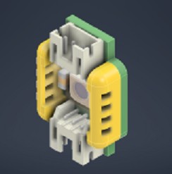
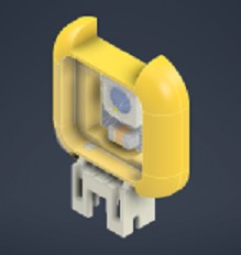
Button design
So this proved to be the most time consuming part (I wrote that before I started debugging!)
The button itself needs to protect the electronics, be rugged and have some kind of locking system. It also needs to actually be possible to fabricate. And most importantly it needs to look good. This is probably the biggest challenge for an engineer, like me.
I’m now up to design revision 7… Help!
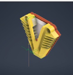
No but actually, design 7 is pretty good…
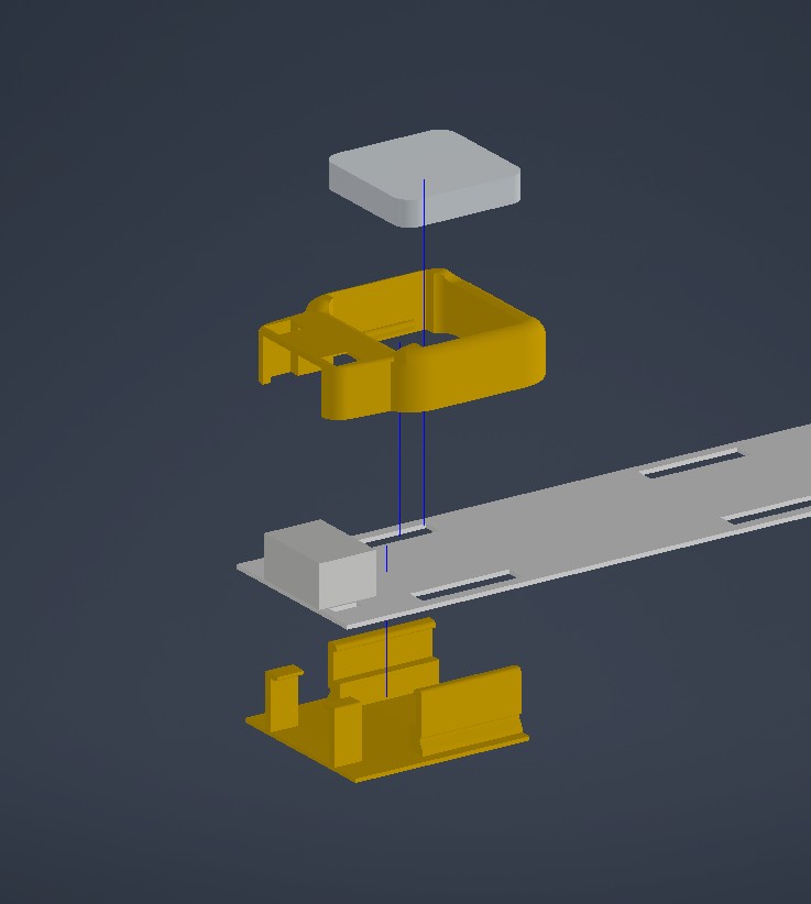
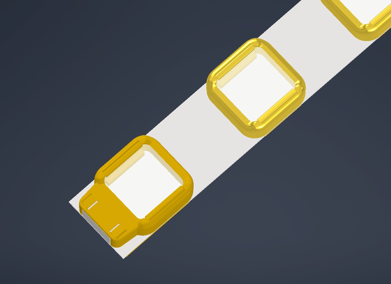
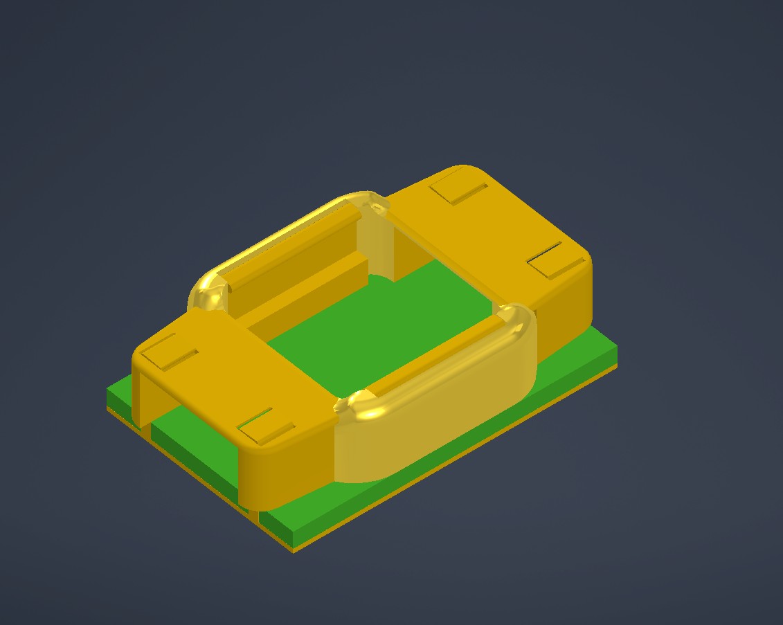
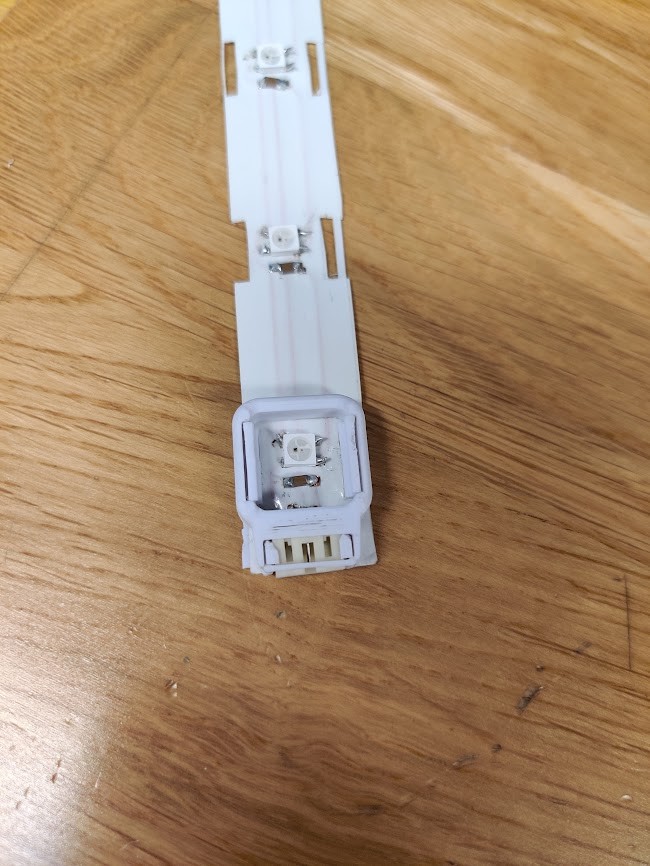
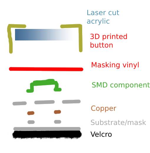
The button consists of a top and bottom shell, and an acrylic window. The shells and window interlock when assembled, hopefully getting a solid join. Furthermore, the flexible PCB is pinned between the shells. In this way, the components shouldn’t experience too much flexing.
And of course, the buttons have three flavours.
One plain, one integrating one JST connector, and one with double JST connectors. THe biggest model is also designed for a 1.6mm PCB, since it doesn’t have to flex.
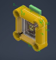
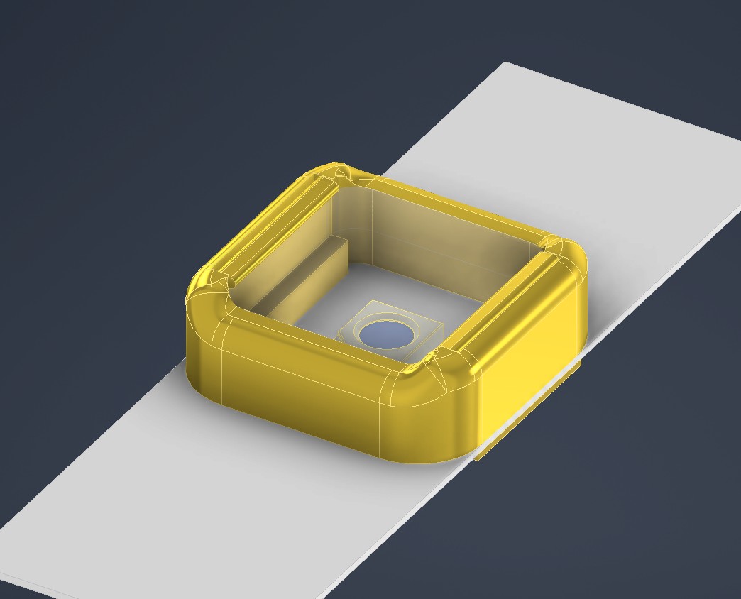
I arranged the buttons in an Inventor assembly. I then created a PCB placeholder in assembly. From this, I sketched out edge cuts and a courtyard as two separate sketches. These were then exported to KiCAD.
LED VEST BOM
| Assembly | Amount | Item | Price/unit | Price total | Link |
|---|---|---|---|---|---|
| LED strip | 8 | WS1812B Neopixel, 5050, SMD | 0,3727 | 2,9816 | https://www.digikey.fi/en/products/detail/adafruit-industries-llc/3094/6058485 |
| 8 | 10uF SMD Capacitor | 0,109 | 0,872 | https://www.digikey.fi/en/products/detail/kemet/C1206C106K4PAC7210/12701324 | |
| 1 | Flexible substrate | 0 | 0 | https://www.digikey.fi/en/products/detail/3m/80610974364/4571237?s=N4IgTCBcDaIMwFsAEB2ADARjXALATjTBRAF0BfIA | |
| 6 | Button upper shell, type 1 | 0 | 0 | https://octofiber.com/2-85mm-pla-bronze-filament-0-75kg.html | |
| 6 | Button lower shell, type 1 | 0 | 0 | https://octofiber.com/2-85mm-pla-bronze-filament-0-75kg.html | |
| 2 | Button upper shell, type 2 | 0 | 0 | https://octofiber.com/2-85mm-pla-bronze-filament-0-75kg.html | |
| 2 | Button lower shell, type 2 | 0 | 0 | https://octofiber.com/2-85mm-pla-bronze-filament-0-75kg.html | |
| 8 | acrylic form cut window | 0 | 0 | https://www.etra.fi/fi/akryylilevy-xt-kirkas-3mm-10540003537 | |
| 2 | 3-pin connector, JST | 0,326 | 0,652 | https://www.digikey.fi/en/products/detail/adafruit-industries-llc/4391/10824267?s=N4IgTCBcDaIFYGcAuACADgCxQZgLRoEsA7EAXQF8g | |
| 1 | 30cm velcro strip, hook side. | 0 | 0 | N/A | |
| 1 | red vinyl, 20cm strip, for masking. | 0 | 0 | N/A | |
| Individual leds | 2 | WS1812B Neopixel, 5050, SMD | 0,3727 | 0,7454 | https://www.digikey.fi/en/products/detail/adafruit-industries-llc/3094/6058485 |
| 2 | Button upper shell, type 3 | 0 | 0 | N/A | |
| 2 | Button lower shell, type 3 | 0 | 0 | N/A | |
| 2 | acrylic form cut window | 0 | 0 | N/A | |
| 4 | 3-pin connector, JST | 0,326 | 1,304 | https://www.digikey.fi/en/products/detail/adafruit-industries-llc/4391/10824267?s=N4IgTCBcDaIFYGcAuACADgCxQZgLRoEsA7EAXQF8g | |
| 2 | 3cm velcro strip, hook side. | N/A | |||
| Controller pcb | 1 | C1 10uF | 0,109 | 0,109 | https://www.digikey.fi/en/products/detail/kemet/C1206C106K4PAC7210/12701324 |
| 1 | C2 100uF | 0,67 | 0,67 | https://www.digikey.fi/en/products/detail/united-chemi-con/APXF6R3ARA151ME40G/5824773 | |
| 1 | J2 Conn_PinHeader_UPDI_2x03_P2.54mm_Vertical_SMD | 0,38 | 0,38 | https://www.digikey.fi/en/products/detail/amphenol-cs-fci/10125394-T0803ALF/7589635 | |
| 1 | J3 Battery holder 3x AAA | 1,68 | 1,68 | https://www.digikey.fi/en/products/detail/keystone-electronics/2479/303824 | |
| 1 | Conn_PinHeader_1x03_P2.54mm_Horizontal_SMD | 0,326 | 0,326 | https://www.digikey.fi/en/products/detail/adafruit-industries-llc/4391/10824267?s=N4IgTCBcDaIFYGcAuACADgCxQZgLRoEsA7EAXQF8g | |
| 1 | SPH0645LM4H I2S MICROPHONE BOARD, | 6,4 | 6,4 | https://www.digikey.fi/en/products/detail/adafruit-industries-llc/3421/6691114?s=N4IgTCBcDaIIYBM4DMBOBXAlgFwASbAGcQBdAXyA | |
| 1 | J5 Conn_PinHeader_1x05_P2.54mm_Vertical_THT_D1mm | 0 | 0 | N/A | |
| 1 | Q1 MOSFET_N-CH_30V_1.7A | 0,38 | 0,38 | https://www.digikey.fi/en/products/detail/nextgen-components/AO3400-5-8A/14288066 | |
| 5 | Resistor 1206 | 0,09 | 0,45 | https://www.digikey.fi/en/products/detail/yageo/AC1206FR-10510RL/14286769 | |
| 2 | R_Potentiometer_Small | 0,91 | 1,82 | https://www.digikey.fi/en/products/detail/bourns-inc/PTV09A-4020F-B102/3781123 | |
| 1 | SW1 BUTTON_B3SN | 0,5 | 0,5 | https://www.digikey.fi/en/products/detail/e-switch/TL1100F160Q/59082 | |
| 1 | SW2 SWITCH_AYZ0102AGRLC | 0,81 | 0,81 | https://www.digikey.fi/en/products/detail/c-k/AYZ0102AGRLC/1640108?s=N4IgTCBcDaIIIE0BaAGAjCscDiAlAMgMIgC6AvkA | |
| 1 | U1 Regulator_Linear_LM3480-3.3V-100mA | 0,69 | 0,69 | https://www.digikey.fi/en/products/detail/texas-instruments/LM3480IM3-3-3-NOPB/270720 | |
| 1 | U2 Microcontroller_ATtiny1614-SSFR | 0,86 | 0,86 | https://www.digikey.fi/en/products/detail/microchip-technology/ATTINY1614-SSFR/7354615 | |
| 1 | 1 Shottky diode | 0,21 | 0,21 | https://www.digikey.fi/en/products/detail/infineon-technologies/BAR8802VH6327XTSA1/2337503 | |
| controller misc. | 3 | AAA batteries | 0,64 | 1,92 | https://www.digikey.fi/en/products/detail/energizer-battery-company/E92VP/14267524 |
| 1 | Lower shell, 3D printed | 0 | 0 | N/A | |
| 1 | Upper shell, 3D printed | 0 | 0 | N/A | |
| 2 | Pot knob, 3D printed | 0 | 0 | N/A | |
| 4 | M3 screw. | 0 | 0 | N/A | |
| 3 | JST 3pin leads | 0,7 | 2,1 | https://www.digikey.fi/en/products/detail/adafruit-industries-llc/4336/10650639 | |
| 3 | Velcro strip, loop side. | 0 | N/A | ||
| Misc. | 1 | Humpsvakar band vest | 0 | 0 | https://humpsvakar.fi/ |
| Total cost | 25,86 | € |
PCB manufacturing
I laid out the flexible PCB in KiCAD
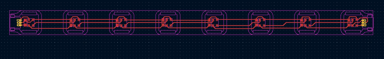
The board itself was fairly straight forward design. Traces are quite thick, 0.6mm to account for the manufacturing process. The courtyard and edge zones made it really easy to get the buttons centerd to the apertures.
The ready boards were exported to SVG using KiCAD’s plot function. Or they should have been. I used KiCAD export->SVG instead.
Opening the files in Inventor, I noticed that the Export function draws traces as single vectors. Oh well, nothing that outline stroke and pathfinder can’t fix :D
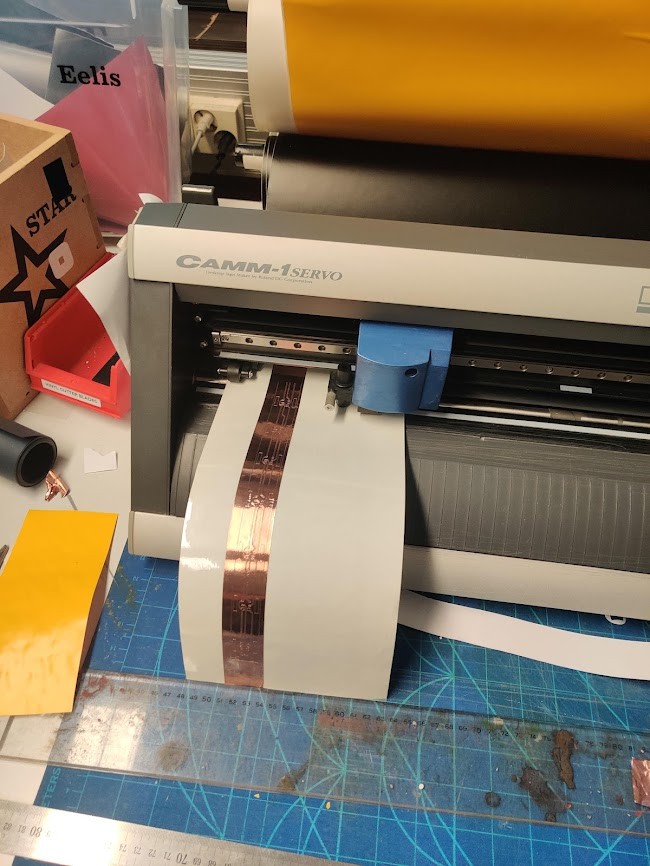
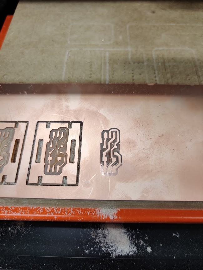
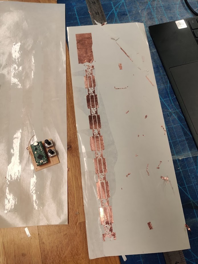
Flexible PCBs are made with the vinyl cutter, with two magical ingedients. copper tape and cuttable, heat resistant substrate.
I’ve written about the process in the week 4 Assignment
I could only find a thin strip variant of the copper tape at Fablab, but that fortunately wasn’t a big issue, since my board is so narrow.
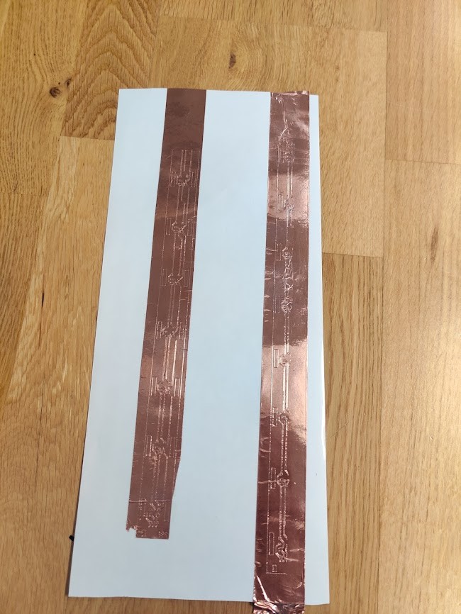
A couple of attempts failed, when the cutter hit it’s limits. I redid using “roll mode” to eliminate the height limit.
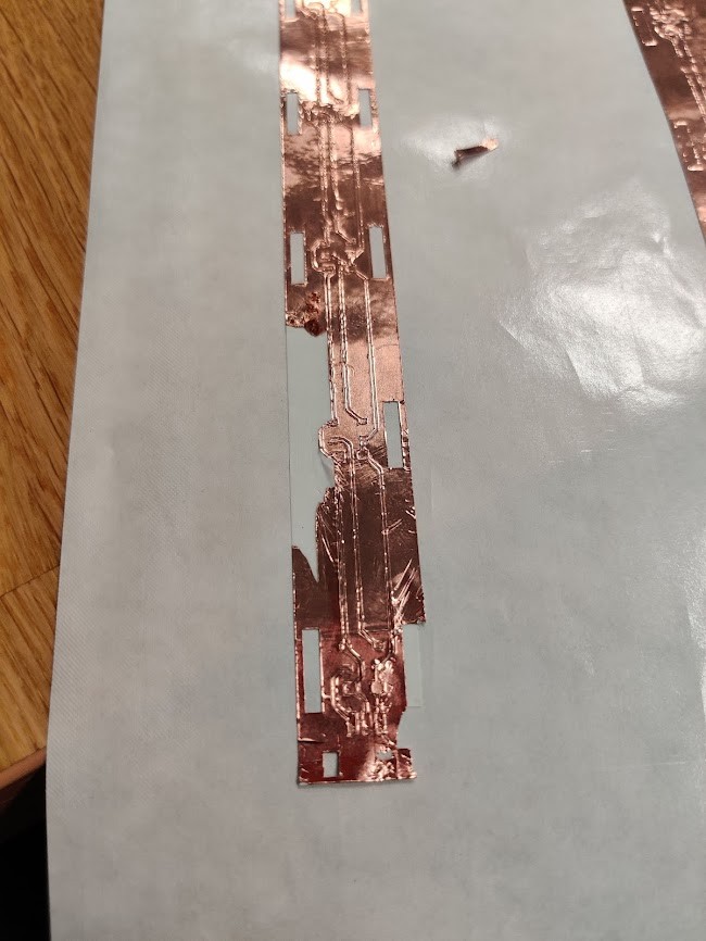
The ruined pieces were also useful as a testbed. Turns out, that my cutting force was a bit too high, and the substrate also got cut quite deep. This combined with that the copper glue unexpectedly was stronger than the substrate’s meant that weeding the traces like this would rip everything off!
To combat this, I glued another layer of substrate under the first one. In this way, I could use the first layer as part of the weeding.
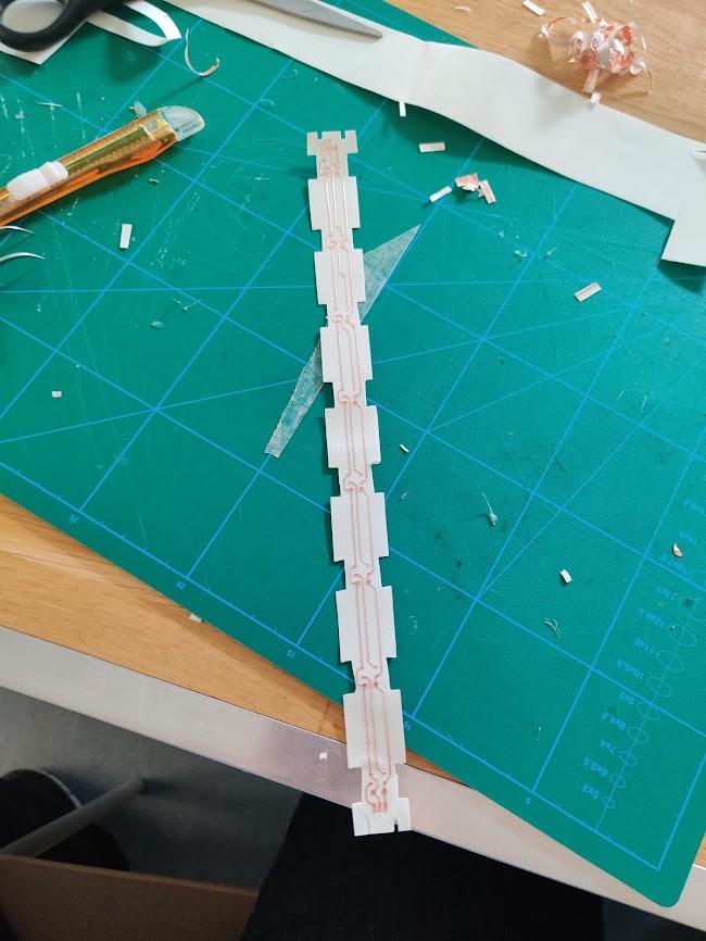
Weeding complete!
I cut a separate solder mask, which I aligned on top. This not only makes soldering easier, but also attaches the traces more securely to the board. Soldering was uneventful and everything is going to plan!
The edges of my different layers were a bit uneven. so i trimmed them using a paper guillotine fablab happened to have handy. I might have trimmed a bit too much, but we’ll fix that in post.
This is the approximate layout for the layers. 9 in total!
The standalone pixels took way more time than expected. First off, my boards were all kinds of messed up, with too thin traces.
Not to forget boards ruined due to unlevel bed :/. Eventually the boards were ready though.
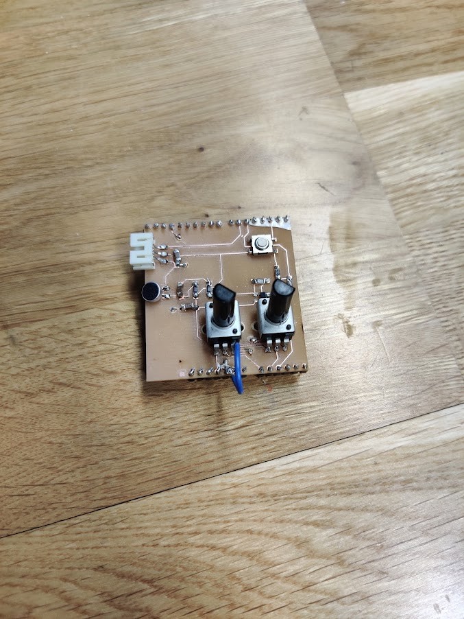
For driving the leds, I’m using my input devices Arduino shield. My input device, the analog mic, doesn’t work, but At least the Arduino, pots and buttons are good.
Testing
So testing didn’t start well. the LEDs wouldn’t light up. Furthermore, the strip pulled too much current from the Arduino, making it brown out. Not good…
After hours of searching for short circuits, I found the issue:
The KiCAD symbol is “wrong”!
~~Turns out that the KiCAD symbol for neopixel has the VCC and VDD pins flipped. I’ve been running reverse polarity on my leds all the time! Oof~~
Hi I’m from the future. The lib symbol was right all along In reality, the issue was that I had connected VDD and VSS wrong. ~~Turns out, the S in VSS doesn’t mean source~~ Okay i read up on this. the Neopixels use the same nomenclature as FETs. Where Vss indeed means source voltage . Of course, the source of a FET is either negative or at ground, whereas the Drain (Vdd) is positive. I should just have read the datasheet… Okay Flashforward over.
Nervously, I flipped the two power wires in the JST connector
The leds light up! At least some of them. A couple of the solder connections seem to be bad. If I have to make another strip I will definetely make the solder pads bigger. And fix the neopixel symbol. If I can figure out how…
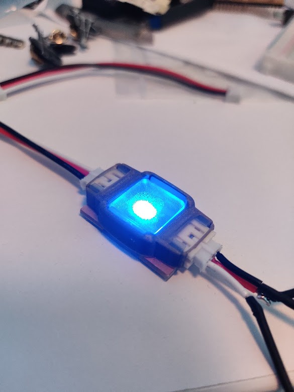
One of the standalone LEDs works. The other one doesn’t for some reason.
Implementations, problems, fixes. More problems
So good news and bad news.
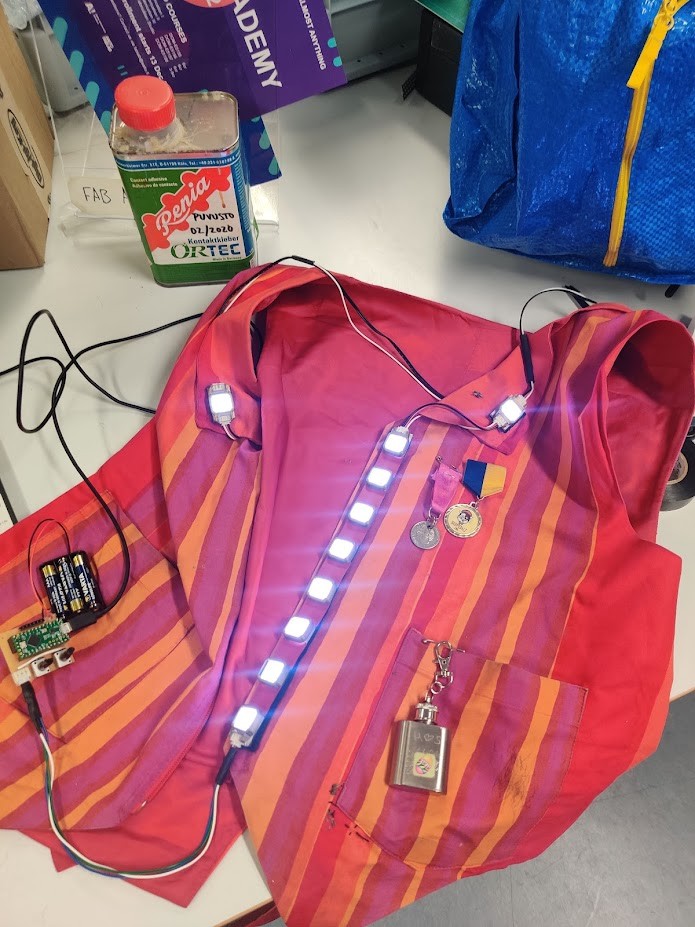
Good news is, that the strip works!
And it looks awesome 🤩
Bad news is that it doesn’t work very well.
First off: The JST connectors are quite strong. a bit too strong. Especially when SMD mounted, they tend to rip off the board! Especially the connections on the flexi boards are at risk.
Second: the strip has already developed some bad connections. This won’t do at all for a wearable. Clearly we need more copper in the flexing parts.
Third: The Arduino UNO shield is a bad driver when the buttons are installed. Its way too bulky
Need to figure out a more portable microcontroller.
The individual leds are fine I guess. Except that they’re still incorrectly wired!
Button strip, v3.1
So KiCAD has a feature called filled zones. With that I can essentially paint a box that will get filled with whatever net value I want. Defaults are VCC and GND, but by checking “hidden nets” one can even put in the communications line.
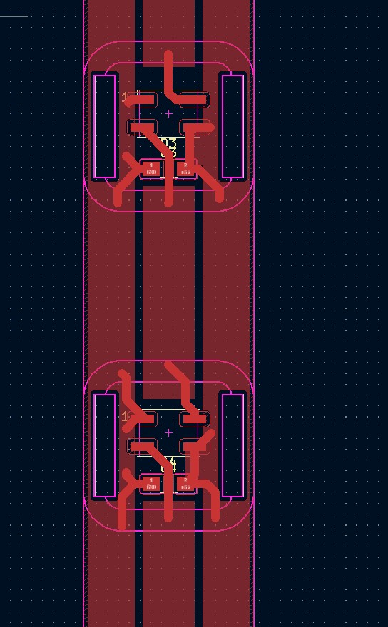
As you can see, the amount of copper has increased significantly. Hopefully our durability as well.
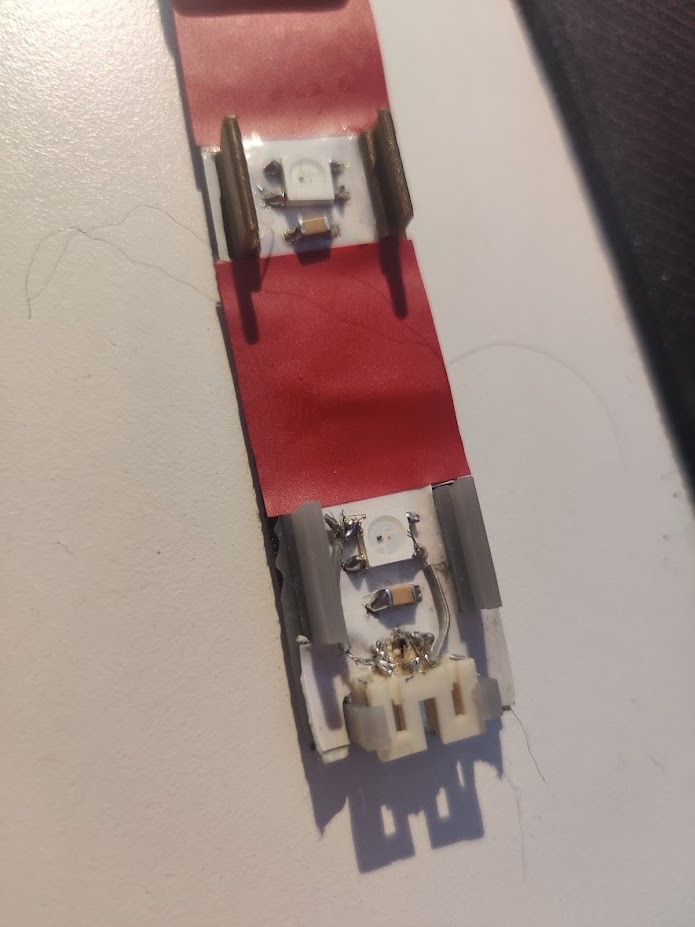
For the connectors, I will try using A through hole design, with the pins getting inserted through the PCB and bent on the other side before soldering. I’ll also glue them to the PCB to reduce strain on the copper.
v3.1, results.
As mentioned previously, I have been using the wrong polarity on the neopixels. This applies to the individual leds as well.
As the individual ones actually function quite well, I don’t want to redo them. Another option would be yet another hacked cable. But I have way too many of those already in the project.
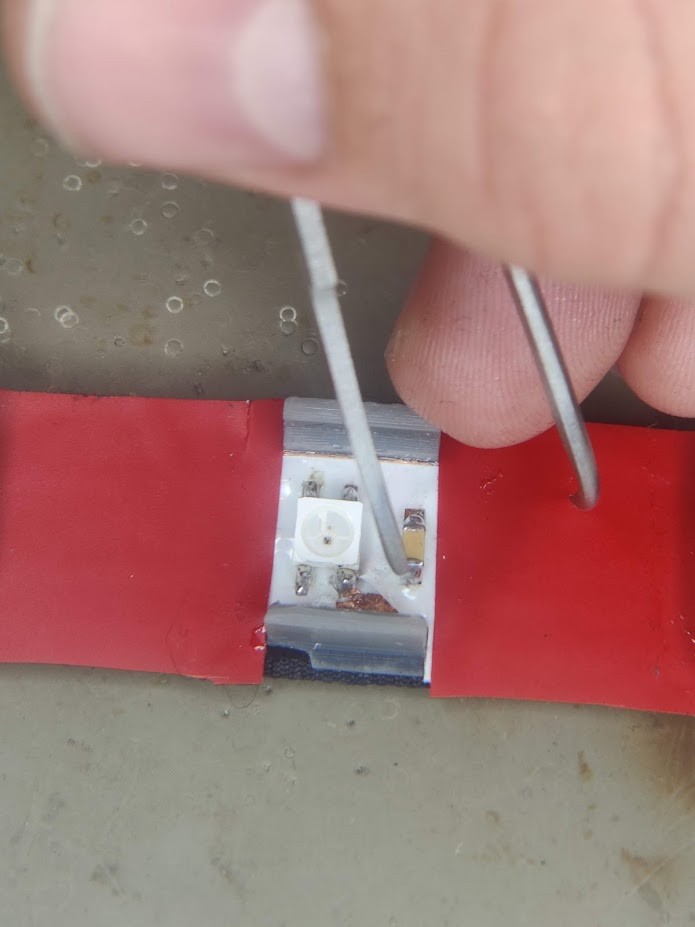
Instead, I realized that I can desolder and rotate the LEDs 180 degrees. This way, the polarity flips on the pins. By connecting the old output connector as input, the signals are routed correctly as well.
I did rip off some of the pads while desoldering. But on the other hand, my solder jumpers seem to work!
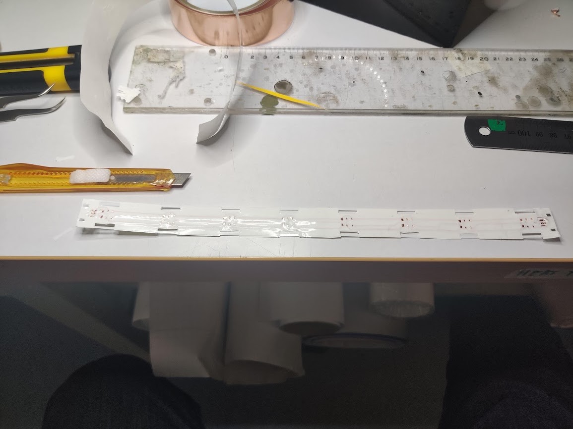
For the strip, the process was similar to last time. I reduced cutting force to 70g this time, to keep the substrate more intact.
Ironically, weeding was much slower this time, since the copper would often break when pulled, especially at corners. Maybe I’ve accidentally invented an easier method with the first attempt?
Anyway, Rest of the assembly was very similiar to the first time.
As usual, the board didn’t work on assembly.
One problem was with the input connector. The VCC line got an insufficient connection with the pad, since it goes under the connector, and was thus hard to solder. The solution was to solder a jumper from the connector to the LED pad.
(Ignore the second jumper: I ingeniously jumped signal to ground, and spent a bunch of time debugging that 🤦♂️.)
The other issue was the signal not getting through all the way. This turned out to be due to a badly weeded connection on the PCB. a bit of surgery solved that.
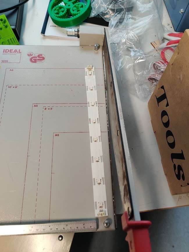
But now finally, we’re in business again!!
After solving the initial issues, the new LED strip is pretty solid! Bending no longer causes connection issues!.
At this point I took a risk. We had a little party with the orchestra for spring end. So I took the vest there. Durability testing at this stage of the process is… risky. But it passed! Instant hit with the rest as well!
Cable routing
With the vest miraculously still functional after last night. I wanted to figure out how to route the cables. Here, The sewing workshop upstairs proved very useful!
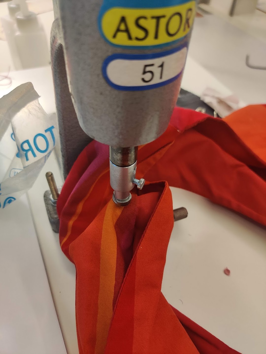
It turns out, they have a way to make riveted holes in fabric. This is usually meant as a way to reinforce holes for ropes etc. But works nicely for cables as well!
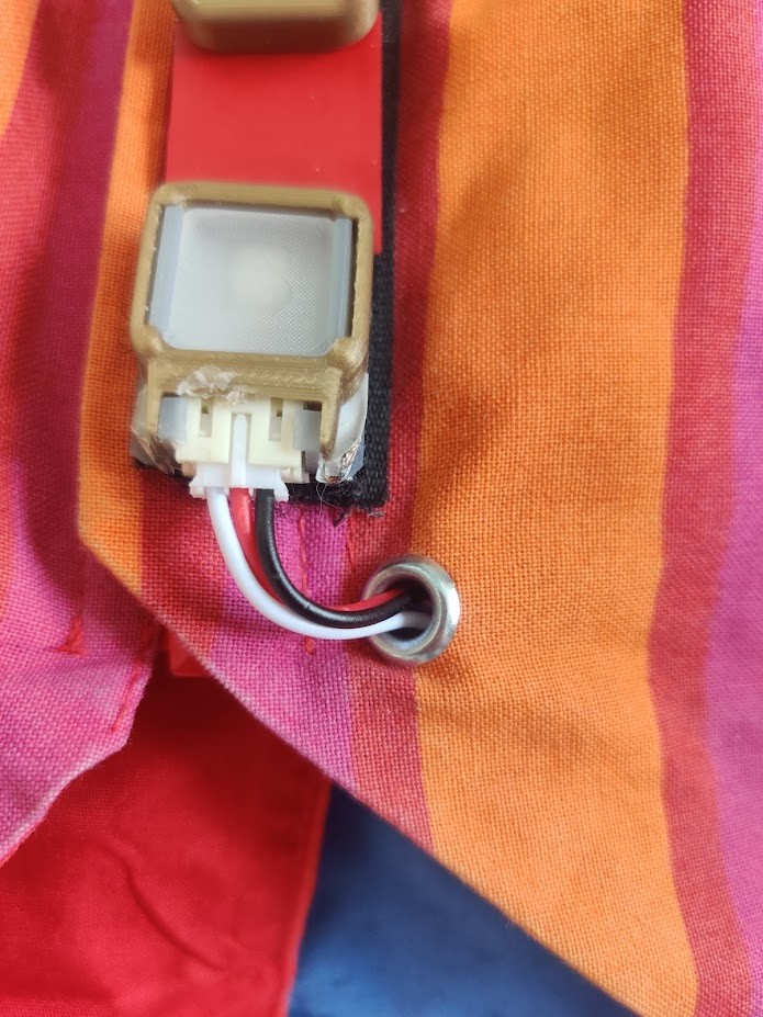
I now have a bunch of these in the vest, and they hide the cabling really well! Only step still is to secure the cable that goes around the back. I will probably do that with simple sewing.
LED controller, D11C
For fab academy, one of the goals is to get the final project to work with an embedded microcontroller. Thus, the Teensy won’t do.
I don’t need that much peripherals for this project, so in principle, an Attiny412 could work. However, the Attiny uses an UPDI programmer for programming, I’d much rather use USB directly.
Enter our old friend, the D11C. The D11C was used for the UPDI programmer, but is a fully featured microcontroller in it’s own right, and can thus be used for this project!
Looking at the Datasheet, and this handy pinout I found, we can see that the D11C as well, is pretty adaptable.

For a 32-bit chip, 16k is a fairly low amount of flash memory, but my program isn’t that complicated. the current Teensy SW uses about 10k, so there is even room to expand!
OF the 14 pin SOIC, two pins are used for USB, two for power, and 3 for the bootloader. Thus, we are left with 7 for GPIO.
The I2S mic is 3.3V, so our logic shall work with that voltage. With one exception. The Neopixels are worth keeping at source voltage. Thus, their logic needs to be level shifted back to source voltage
Systems we’ll need:
- Digital I2S microphone, two pins.
- Mode select button, 1 pin
- 2x Mode potentiometers, 1-pin each.
- Neopixel output, 1-pin, w 3.3V-5V level shifter.
- USB input
- 4-pin bootloader connection.
- Battery power input + power switch
- 5-3.3V regulator
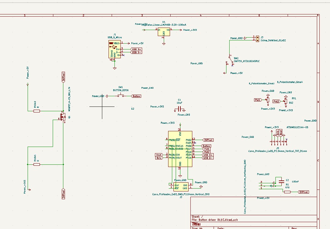
That’s a lot, off to Kicad!
I finally started using Kicad flags, for a more readable schematics. Thanks to Karl for his work figuring out the level shifter, which i blatantly copied. The levelshifter uses a FET and two resistors, how it works, I have no idea. But Karl’s does work so I’m hopeful!
Okay so This article sort of explains the level shifter. It makes sense if one considers tri-state logic, where the microcontroller will actually switch the signal to ground on LOW. Amazingly, this level shifter is even bi-directional. go MOSFET! That feature is not strictly necessary for us, but you can’t get much simpler either!
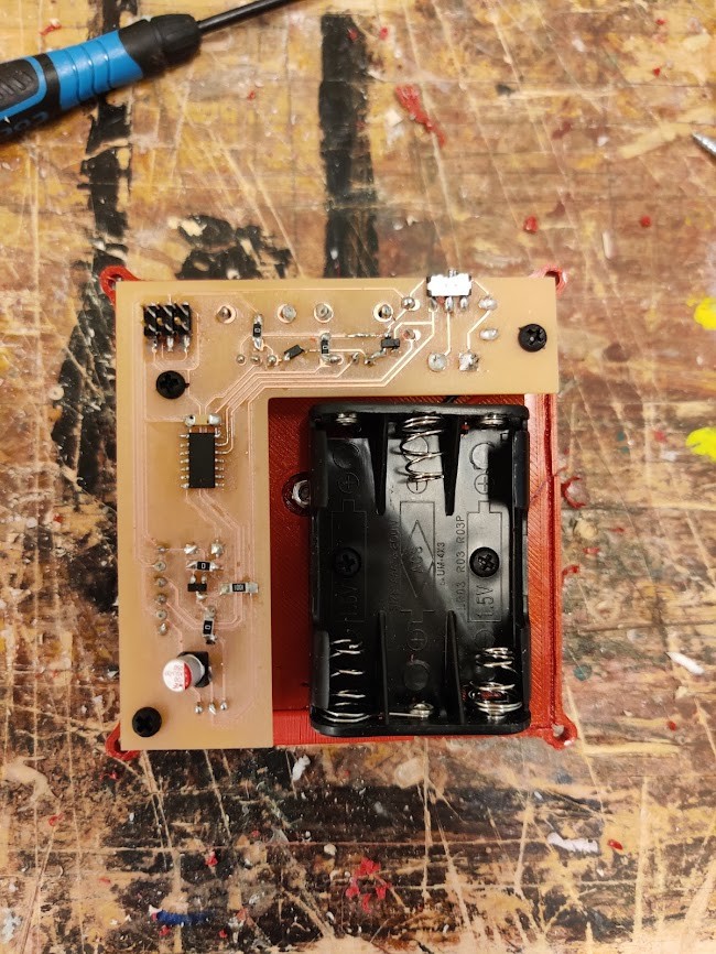
Off to PCB design. I want to use the same battery pack I’ve been using before, with 3x AA batteries. Partially inspired by smartphone motherboards, I configured the board to wrap around the batteries. That way, I can also have controls on top, and the LED connector on the bottom.
Behold!
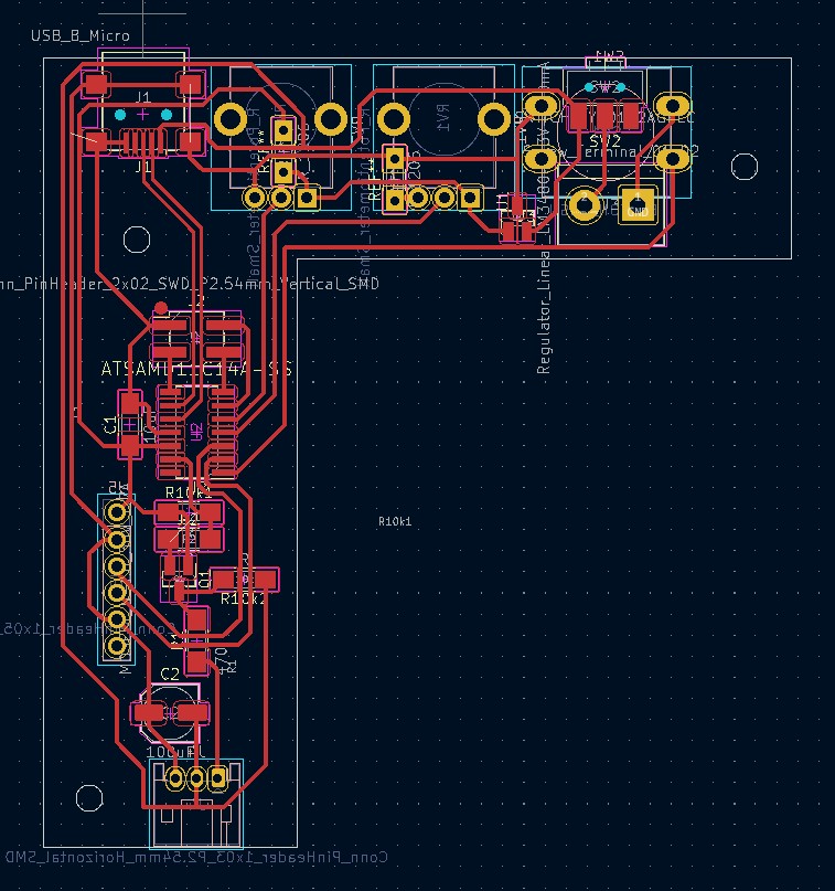
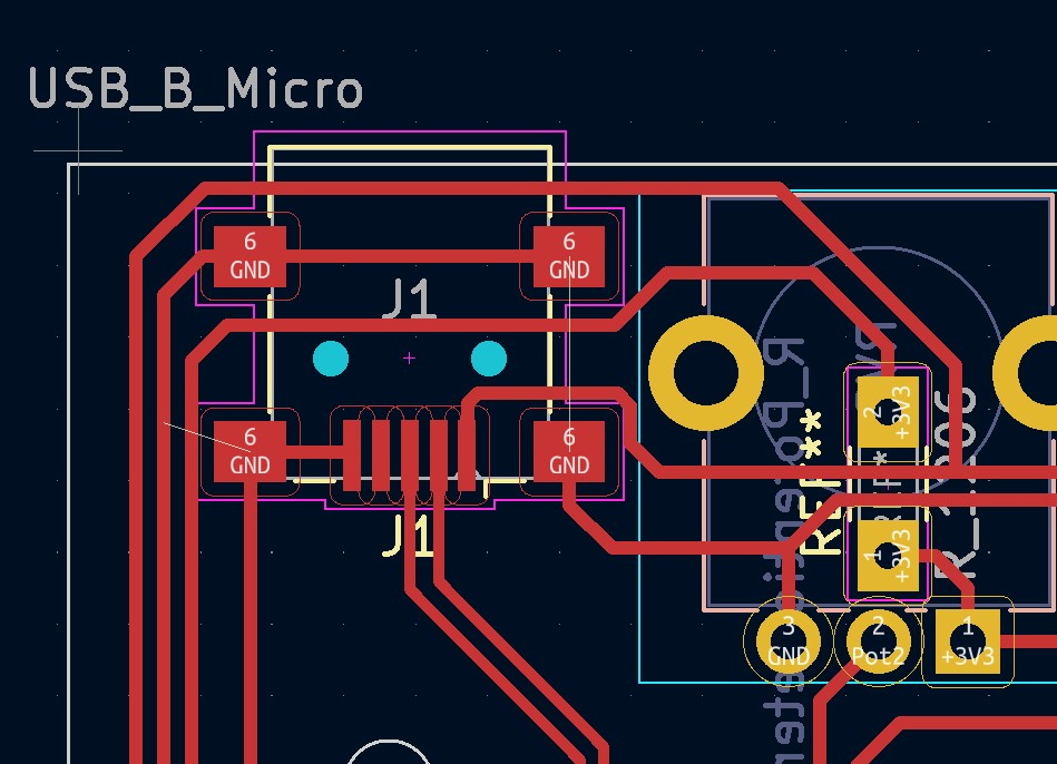
Seeing that the rivet press is broken, the board is designed for single layer. I’m using every trick in the book to make that happen. For instance. why not use the USB casing as a ground jumper! There are three jumper resistors in total as well.
The D11C is well populated, with just a single pin left unused.
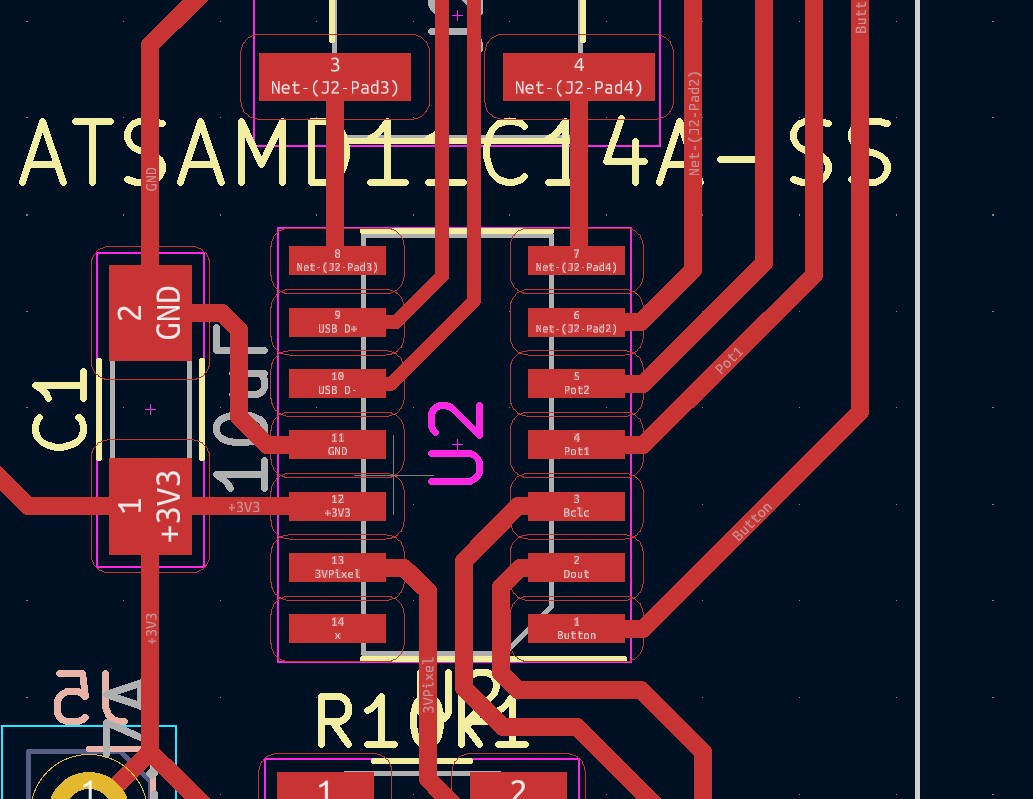
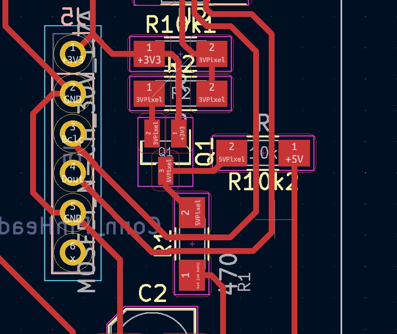
Level shifter circuit is neatly tucked between the processor and connector.
This time, I also remembered to put in mounting holes! These are M2.5, to be used with nylon standoffs available at the lab.
Control circuit, ATtiny 1614
Okay, so a couple of issues surfaced with the D11C.
FIrst off, SAM chips have different instructions than 32 bit ones. For instance, I can’t use Neil’s I2S code as is on a SAM chip. I could conceivably run the I2s library instead, but that will surely deplete the 16k of memory…
Instead, I decided to switch to an 8-bit AVR processor. The Attiny 412 doesn’t have enough IO, So I went with the Attiny 1614. This chip also has 16k of flash, but the 8-bit instructions take much less space.
/i/77443/products/2019-08-05T04%3A53%3A31.915Z-ATtiny_x14.png?1606306133)
Like the D11C, Attiny 1614 is on a 14 pin SOIC, but this time, I need only a single pin for UPDI, Compared to 3 fr the bootloader and 2 for USB. Thus, the microcontroller area is actualloy much cleaner in the new design.
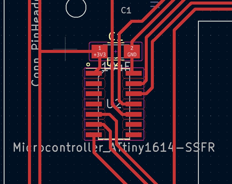
Despite needing a programmer, I think the tradeoff is worthwile.
Electronics housing
Next Step is designing a box for the electronics to live in. It has the following functions:
- Protect the electronics from wear
- Provide interface for the controls and connectors
- Slow water ingress
- Fix the electronics in the pocket
I started by exporting the board STEP file:

From the board i made a master sketch
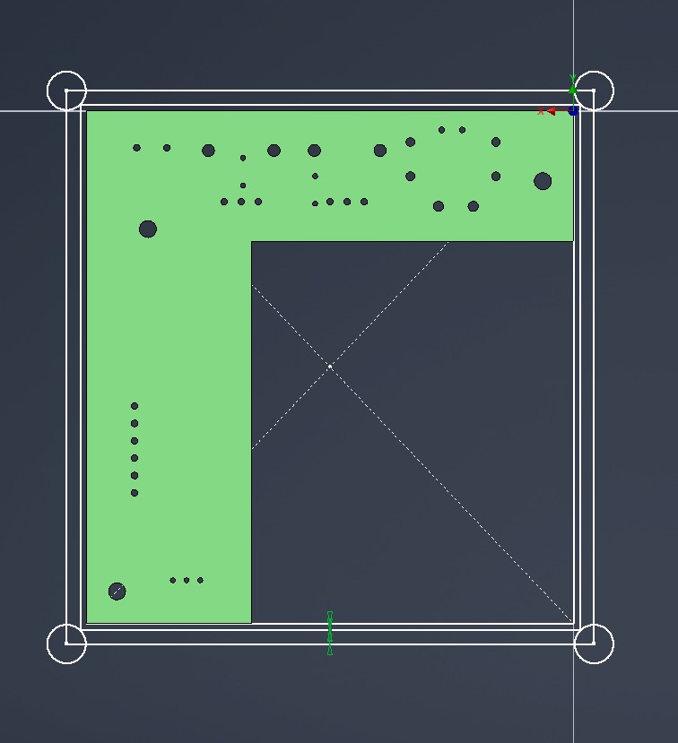
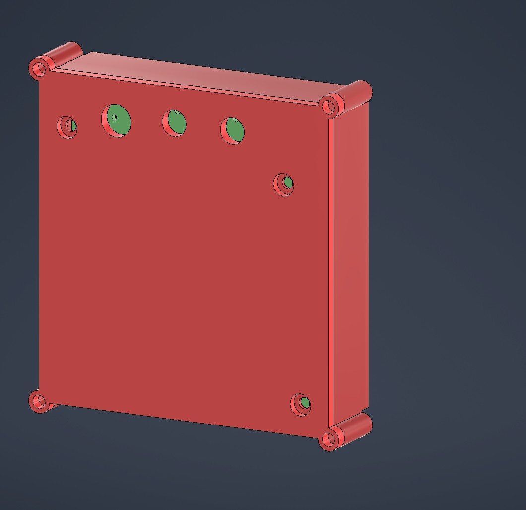
From the master sketch I extruded a box around the board. The box has holes for M3 screws in the corners, which will hold everything together.
During testing I’d noticed that the potentiometers are quite hard to turn by hand. So I wanted to design knobs with a good grip surface for them.
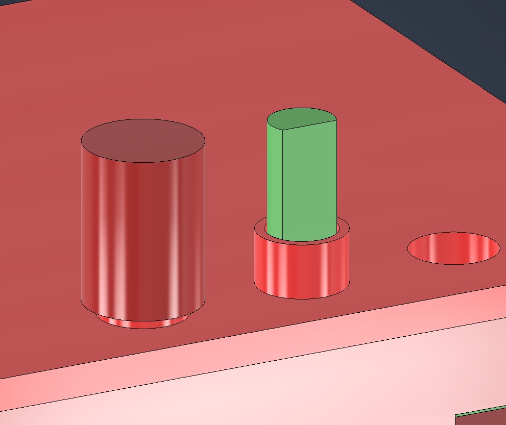
I first modelled dummy pots, and some features around those. The flange around the pot is to prevent dirt and water from getting inside throug the hole.
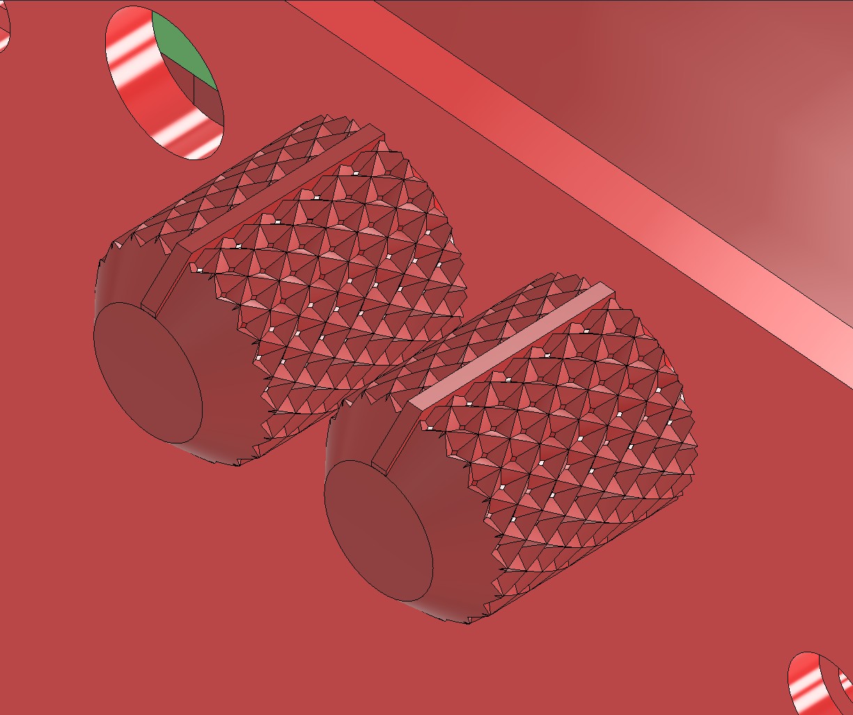
For the grip surface, I went with a crosshatch pattern.
I first swept a triangular shape along a steep spiral pattern around the cylindrical knob. Which i then mirrored.
By circular patterning both, we get a really nice gripping surface.
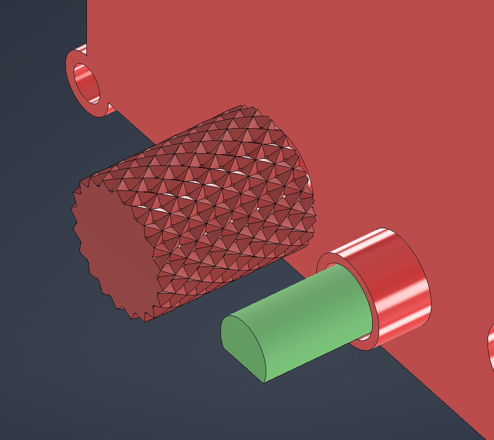
I chamfered the knob ends, and designed an indicator for telling the pot position.
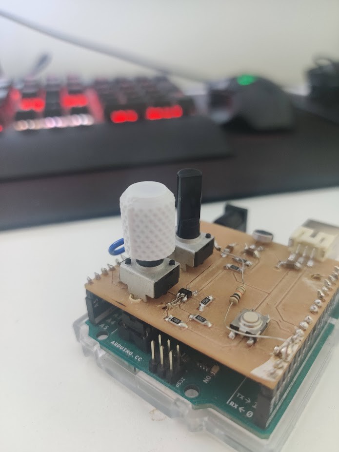
After a quick test print, we can verify that the knob works well!
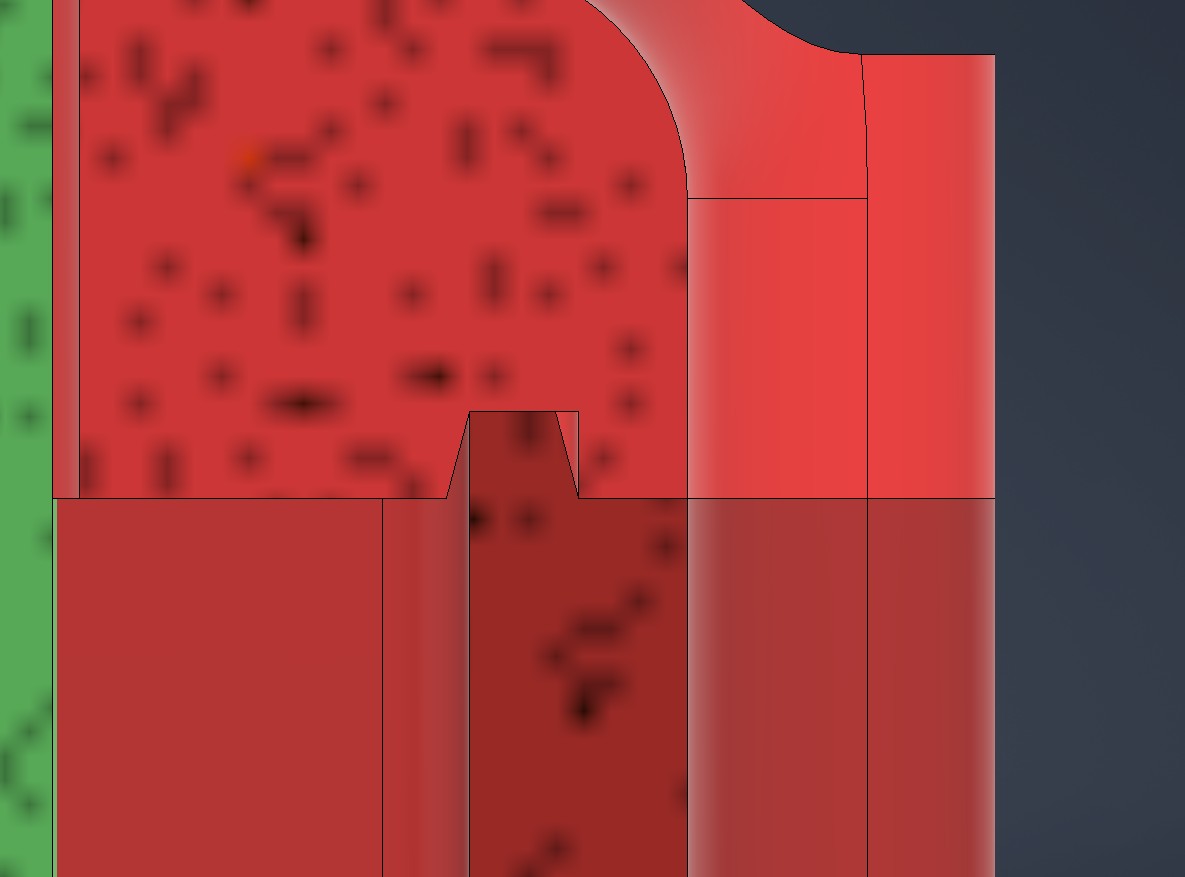
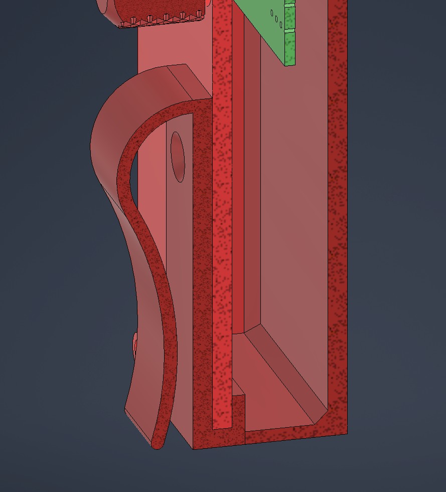
To hinder water ingress, and to hold the two halves together, I designed a flange between the cover and the housing. The flange has a 15 deg draft angle on both sides, to allow for the 3D printed parts to interlock solidly
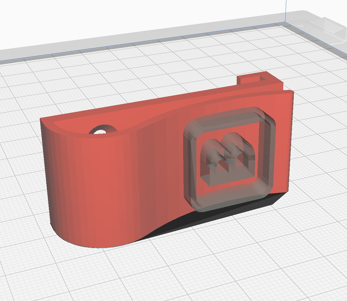
Finally, for preventing the electronics box from moving around the pocket, I designed a clip.
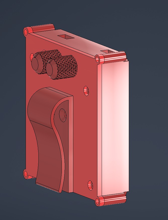
It wraps around the box cover on the bottom, and attaches by two M3 screws on the top. Hopefully I can tighten these with a low profile hex wrench.
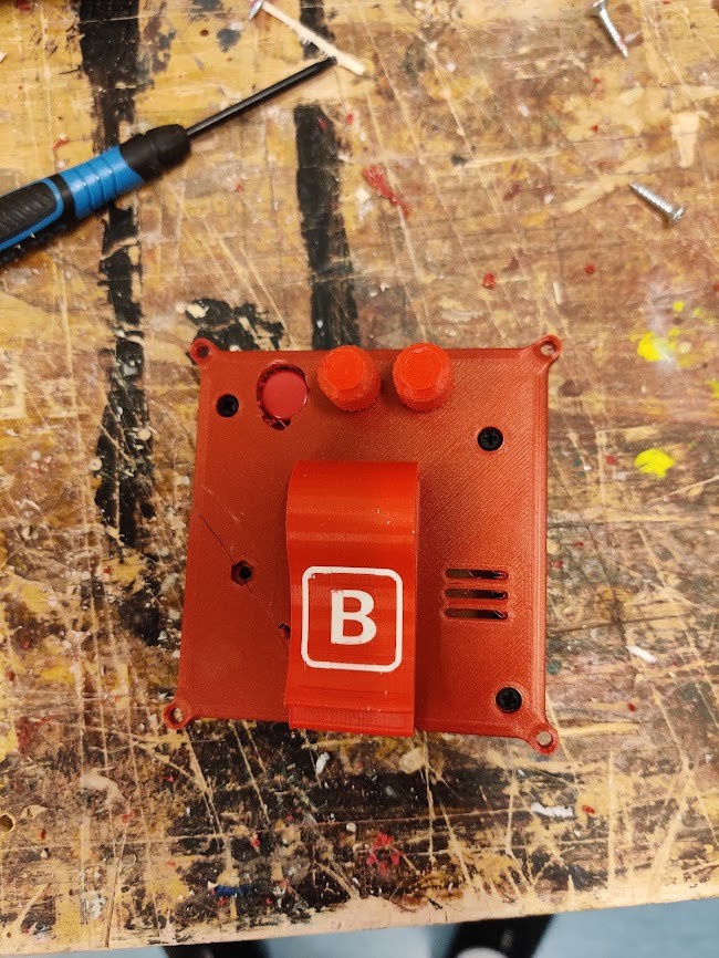
For the clip, I want to have my signature B emoji on the clip. I’m gonna go for dual extrusion 3d printing for this.
I first created a 3D B object using windows 3D builder. This was simply converted from a jpg.
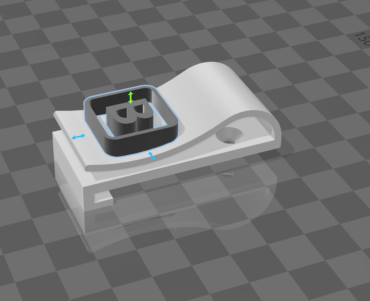
In cura, I can then define the other model as a cutting mesh, that modifies overlaps to use extruder 2.
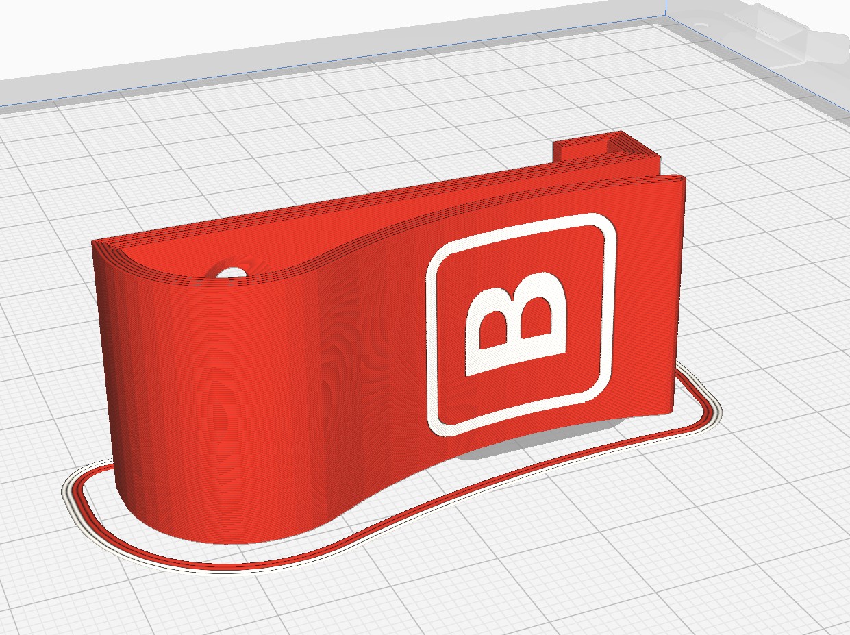
Let’s hope the result looks equally good!
I also added a cover for the battery compartment, so that I don’t need to unbolt the entire casing for battery switching.
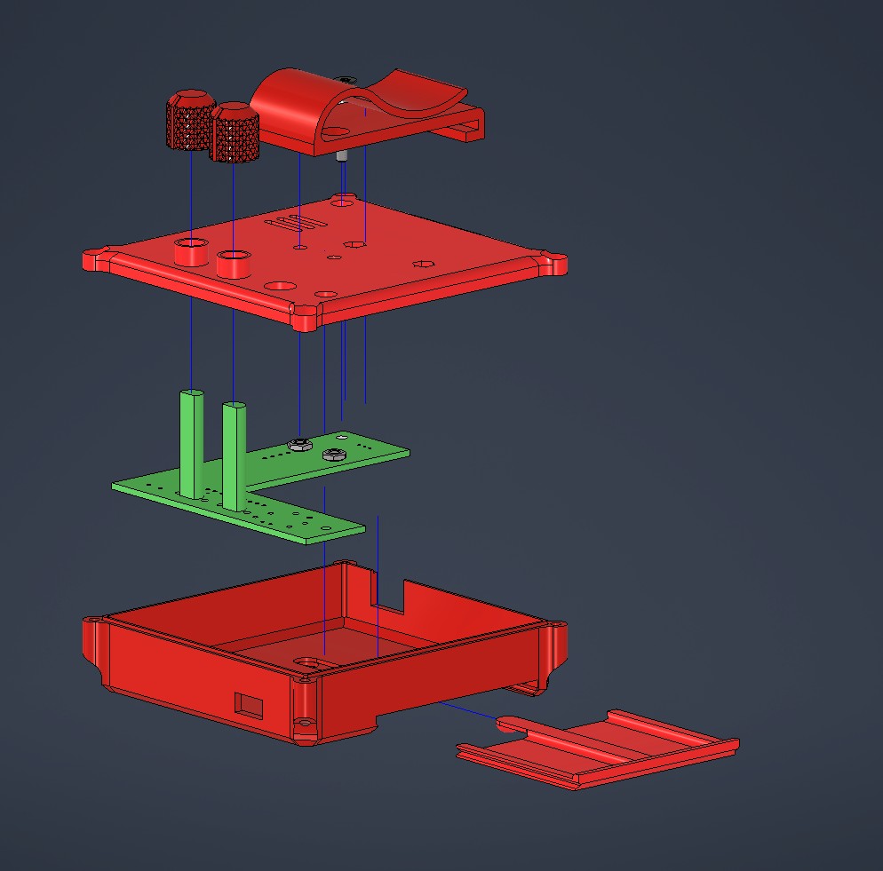
Exploded view of the complete assembly. Some bolts included as well.
Board manufacturing and testing, level shifting woes.
As usual, a couple of problems with the board became evident after manufacture. First off, fablab was out of 1614s! This was solved by cannibalizing some off old boards. OF course, the first two chips were non functional, and many hours of fun were had trying to debug them…
The second is that UPDI provides power as well, and 5V at that. I put the connector on the output side of the regulator. Previous experience indicates, that applying backwards voltage to regulators isn’t a good idea…
As a solution, I wired in a diode between the regulator and UPDI terminal. The microprocessor can take 5V, but the microphone module can’t, So it needs to be disconnected during programming. Oh well.
At this point I got to programming, the neopixel library gave an incompatible clockspeed error. THe error was fixed by following this guide, Just a quick edit to the library files
With the program loaded i plugged in the vest… and got nothing. Confused, I hooked the controller to the oscilloscope.
It turns out, the level shifter gives 2.8V instead of 5. Not great.
At this point i tried different pullup resistances, different mosfets and different voltages, but nothing was working. I even had 3(!) EEs at work look at the damn thing, and nobody could figure out what’s wrong.
I realized, that the level shifter I’m using is designed to be bi-directional. Since I don’t need that feature I could remove the input side pullup. Doing this had an immedeate effect. I then switched the high side pullup fron 10k to 1k and lo and behold… It works!!!
EEs 0, me 1.
Housing integration
For the housing I used a mystery filament (TM) I found at the lab, due to it’s nice color. It turned out that this wasn’t PLA, but cryptically labelled “PG”
Increasing temps made it print fine. A bit too fine. Bed adhesion was so good that one piece broke when i tried to remove it! Superglue time i guess.
It turned out I had got some of the measurements wrong for the housing, so some tuning with the Dremel was required.
The housing halves fit together really nicely, the draft angle on the flange clearly made a difference.
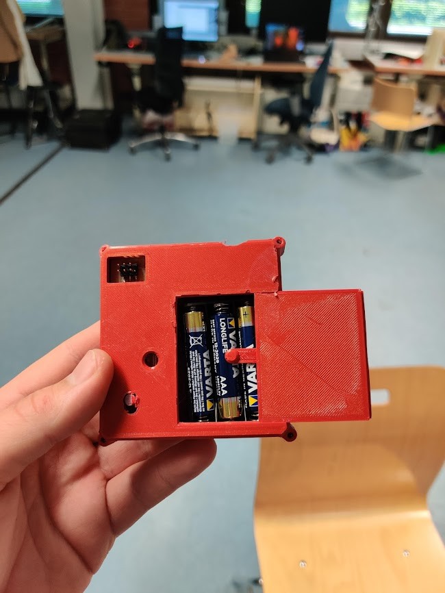
Final product, as installed. In general, I’m really happy with how the controls are accessible and how the control box is held in place!
Future plans
Now with a functioning product, the first step is using it, and testing durability. I suspect the strip itself has a few weakpoints, that might lead to connection issues in the long run. For the next version, I’m also looking to lengthen the lower 3d printed clamshells, to alleviate the weakpoints.
For further developments of the vest, Please see here
Design files
Following are download links for zip files: Arduino INOs Inventor 3D files Kicad designs

This work is licensed under a Creative Commons Attribution-ShareAlike 4.0 International License.