9. Embedded programming
This week was spent actually getting the attiny 412 to do something.
Group assignment
Our group assignment this week was to compare the differences between microcontroller architectures. link to group assignment
Board
Recall the board from week 7:
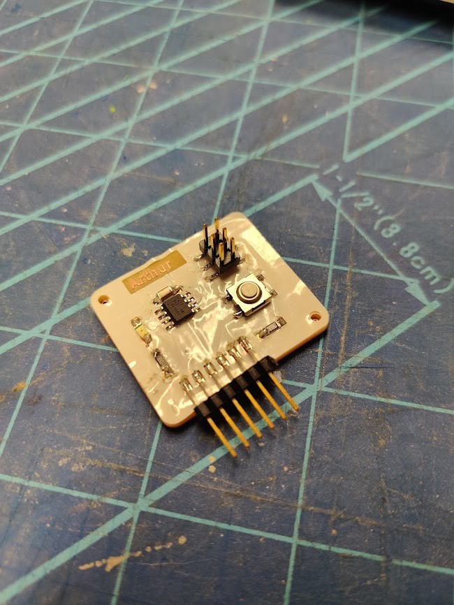
The board is stupidly simple, Its programmed by either UPDI or FTDI and has a push button and a led.
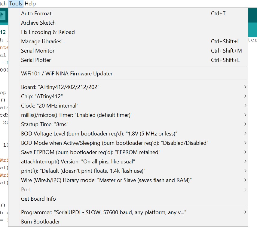
Programming ATtiny 412
To begin with, i used the familiar Arduino IDE for programming the 412.
I had to install some additional stuff to make everything work. this was all quite overwhelming, but thankfully Darren was close by to help. thanks Darren!
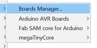
To get the programmer working I needed Fab SAM core for Arduino and for the attiny I needed MegaTinyCore. so far so good.
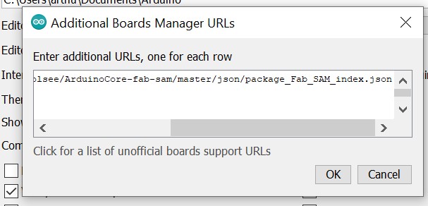
With these installed from the board manager we get a bewildering amount of options.
Most of these can be left as is, with the important ones being the target board.
PSA
IF THE PROGRAMMER BOARD IS SELECTED AS A TARGET, IT WILL GET OVERWRITTEN AND WONT WORK AS A PROGRAMMER ANYMORE! Don’t ask how i know this…
Datasheet
The 412 is provided with an extensive datasheet, almost all of it is gibberish like timing charts, block diagrams, info on registers etc. All of that is handled by the Arduino libraries, don’t worry about it!
The pinout on the other hand is very useful:

As you can see, for an 8 pin SOIC, the pins are incredibly multifunctional. 6/8 pins can act as digital or analog IO, and even support PWM, nice! Pins 0 and 5 support async interrupt, so it’s good that my button is on pin 5. that was totally intentional…
We of course, have 3 pins reserved already, namely for UPDI , and serial TX and RX. Thus, we have 3 pins left of which two are in use. One pin remains unused.
I initially had poor results in getting anything to happen. After messing around with the programmer, it turned out that the issue wasn’t there.
I had made a fatal logical error. I foolishly assumed that pin PA1 would correspond to logical pin 1 in the code.
How foolish. Obviously PA1 is pin 2. Did i mention it’s number on the chip? If you guessed 4 you are correct.
Brown numbers in the pinout diagram are what I should use in the code.
Programming
For my first program, I went very simple, see my code below
Intblink code.
//Simple button interrupt controlled led blinker
//init variables
#define LEDPIN  2

#define BPIN    3

//pin addresses in arduino are offset by +1 to their datasheet equals. took a while to find out!

bool speedb;
int del;

// the setup function runs once when the board is powered
void setup() {
// initialize LEDPIN as an output.
pinMode(LEDPIN, OUTPUT);
//attach interrupt to button. button is configures with a pulldown resistor, so interrupt will be called on RISING signal when the button is pressed.
attachInterrupt(digitalPinToInterrupt(BPIN), intf, RISING);
//initial values for variables.
speedb = false;
del = 1000;
}

// the loop function runs over and over again forever
void loop() {
//set delay according to interrupt bool variable
if (speedb){
    del = 200;
}
else{
    del = 1000;
}
digitalWrite(LEDPIN, HIGH);   // turn the LED on (HIGH is the voltage level)
delay(del);
digitalWrite(LEDPIN, LOW);    // turn the LED off by making the voltage LOW
delay(del);
}

void intf() {
//speedb variable is inverted when interrupt is called.
speedb = !speedb;
}
The program simply toggles between two blink speeds using the button.
(hey eval guys! more video of slightly better, yet custom, boards can be found here)
Arduino UNO
I’ve done some programming on Arduino UNO as well. you can check it out at the LED vest project page
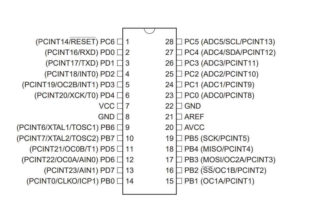
The UNO uses an ATmega328P This is a larger microcontroller on a 28 pin IC. Still AVR though, so programming is very similiar to ATtiny.
Other than that, Arduino has included an built-in USB interface, voltage regulation and other nice things.