9. Electronics production
This week I tried electronics manufacturing, using PCB milling, soldering and more.
PCB milling
Yes, it’s a PCB even if you mill it. I checked.
PCBs, or Printed Circuit Boards, are the key to doing anything more complicated with electronics. With a PCB, one can neatly pre-plan the attachment points and wiring for electrical components, increasing density compared to other methods.
There are many ways to make PCBs, this week we used milling. Milling is a fairly flexible, fast and cheap method to make simple boards in small numbers. On the other hand, mass production, or very dense ad complicated boards will be better served by other processes.
I had never milled a PCB before, but I have CNC milled metal parts before. PCB milling turned out to be fairly easy, more comparable to 3D printing than CNC, in my opinion.
Hardware
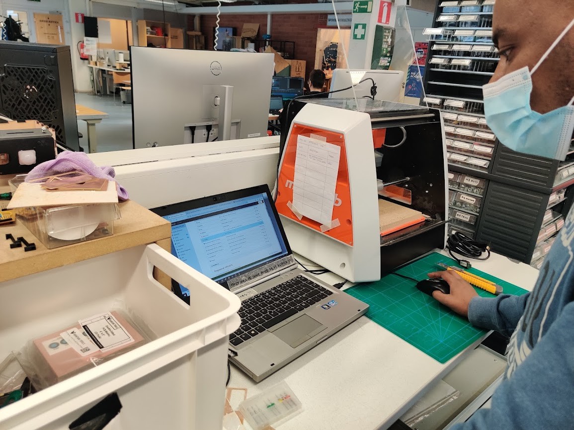
First off the machines, fablab has two PCB capable machines in use, and these models seem to be in almost universal use throughout the fab network:
- Roland MonoFab SRM-20
- Roland Modela MDX-40
Both machines are fairly similiar to use, differing mostly in size, speed and zeroing method. Both can in addition to PCBs be used to mill softer materials, such as wood and polyurethane.
For my first board i used the SRM-20.
Material
PCBs consist of one or more conducting layers, and an insulating substrate. Typically, milling is used for 1-2 layer boards. In my case, i only needed a single layer one.
There are different substrate materials available. We used very basic FR-1, which is essentially paper and plastic composite. Compared to other substrates, FR-1 has lower heat tolerance and can’t thus be used in an reflow oven. On the other hand, its easy to machine and does not produce hazardous particles when milled.
Group assignment
For this week’s group assignment, our task was to characterize the PCB milling process.
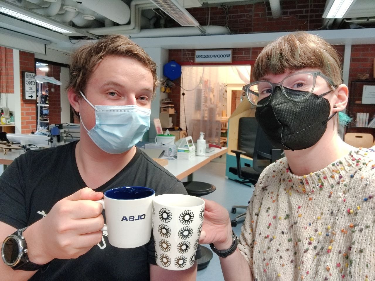
I joined forces with Katie and set out to investigate the mill.
We used the provided test board.

The board is provided in PNG format. To mill it, we need to convert it to gcode.
For this we use MODS. An online modular machining software.
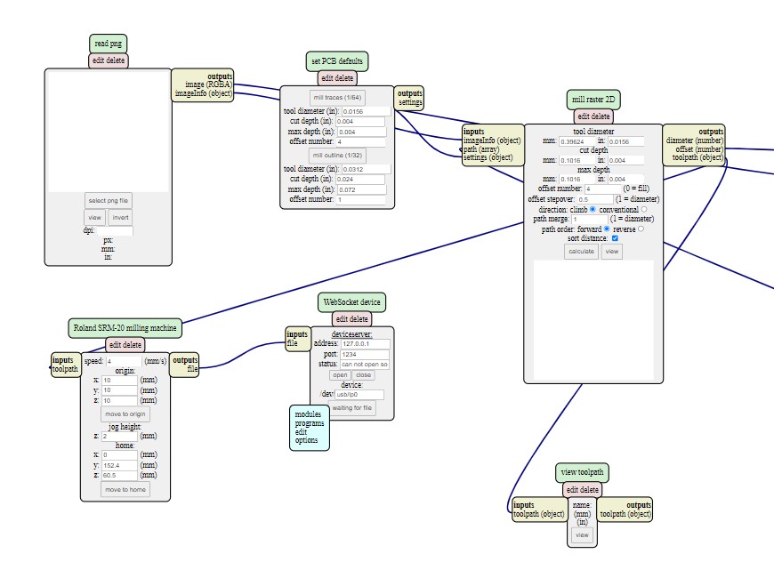
Using mods is quite interesting. In this case, we start by loading an entire pre-written program, “Roland/mill/SRM-20/PCB png” from the server. Mods programs are assembled by chaining various modules inputs and outputs together.
Our particular program takes an png silhouette image, and outputs a ready gcode file for our mill. THe default program outputs the file straight to a server, using the websocket module We can modify this by substituting it for a simple save file module, and save it locally.
Off to the mill. The milling was done with a 0.4mm bit, default settings.
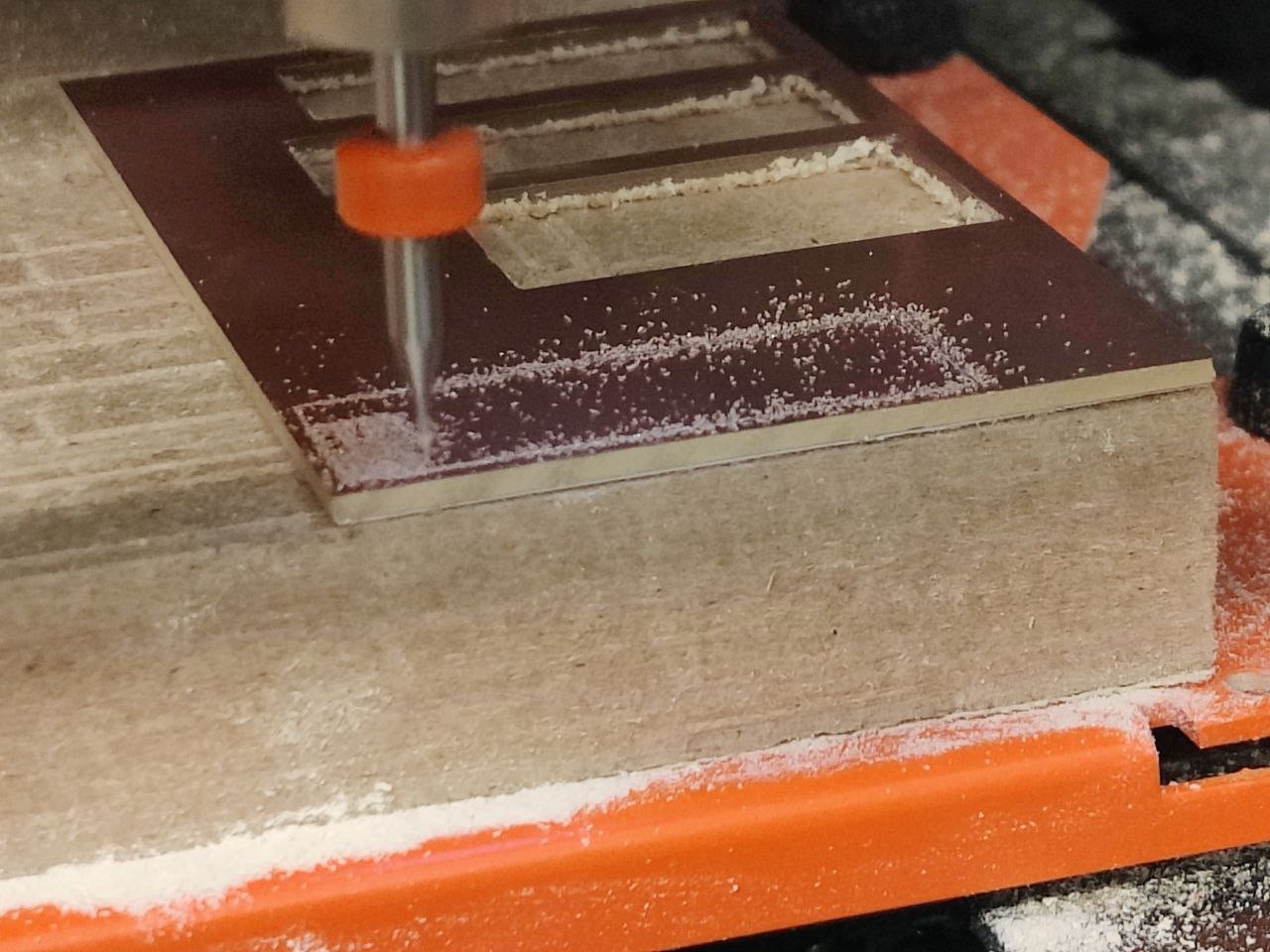
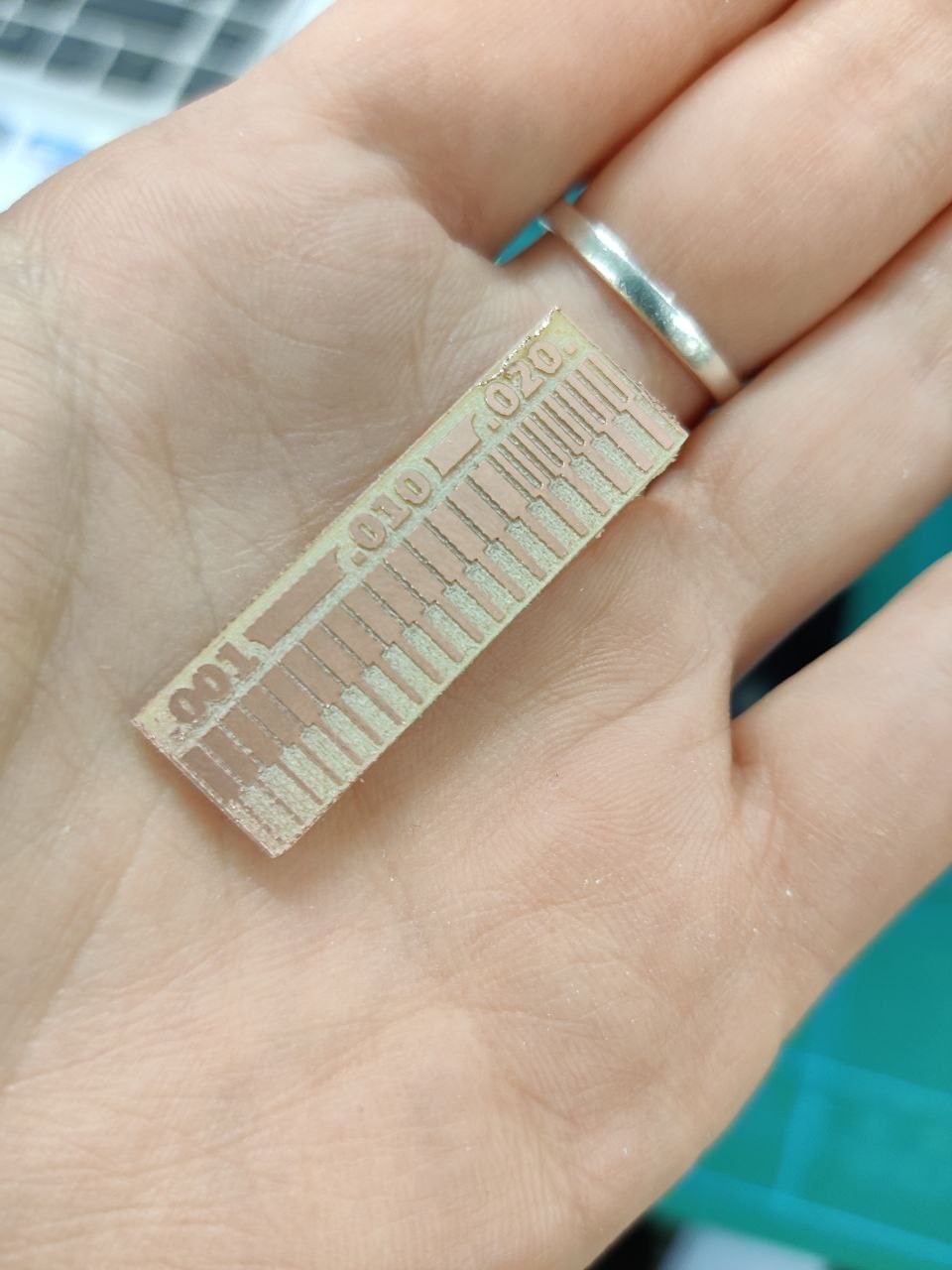
As we can see, the results are quite crisp. only the thinnest line has not milled properly. Default settings seem to work quite well.
UPDI D11C
My first assignment was producing an AVR programmer board.
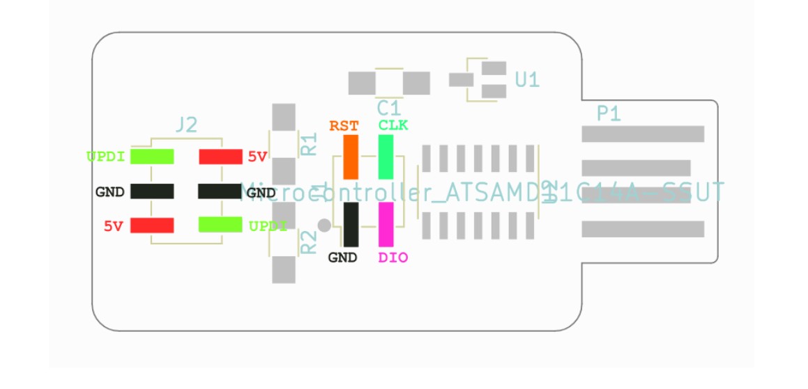
It is a very simple board, with a D11C microcontroller, an output and input header, and various other bits.
The first step was milling the board. Fortunately, ready gerber files were provided. These were then opened in the CAM software, CopperCAM.
CopperCAM is very easy to use. At a minimum, two operations are needed: First, ia fine engraving to cut out the traces, and second an outline milling operation to cut out the PCB. I also wanted to remove the excess copper around the board edges, so I would perform an additiona hatching process. a hatching process. I used the flat mill for hatchin as well to increase speed.
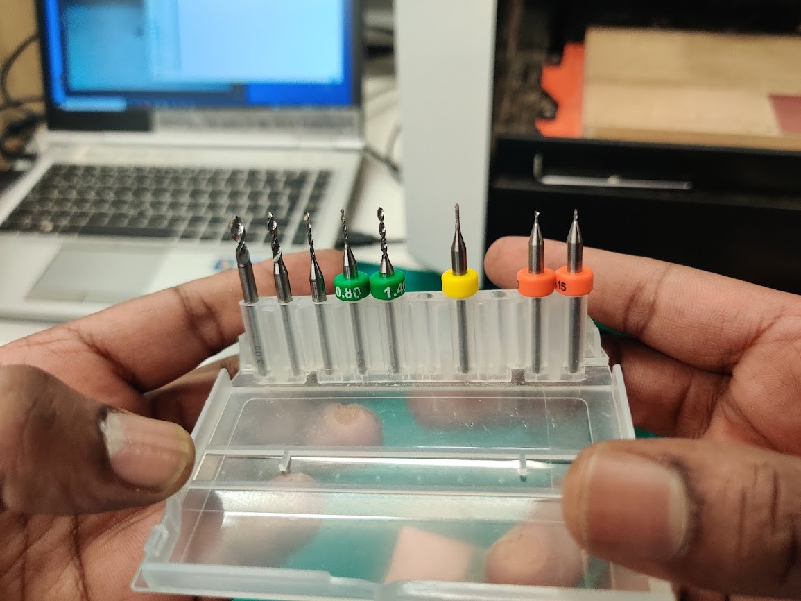
Tool alternatives. From left to right: + Drills, various diameters. + 1mm flat mill + 0.2 & 0.4mm V-mill.
THe engraves are done with the V-mill. ANd cutting with the flat mill. I additionally used the flat mill for hatching, since that is way faster than doing with the tiny V-mill. The SRM-20 tools all run at 10mm/s feed. Speed is just max spindle speed. Very simple. MDX-40 apparently runs a bit faster.
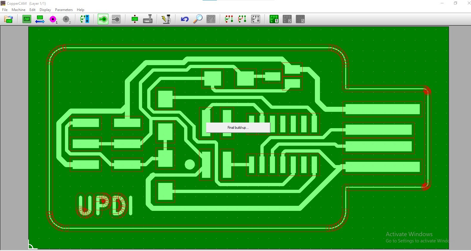
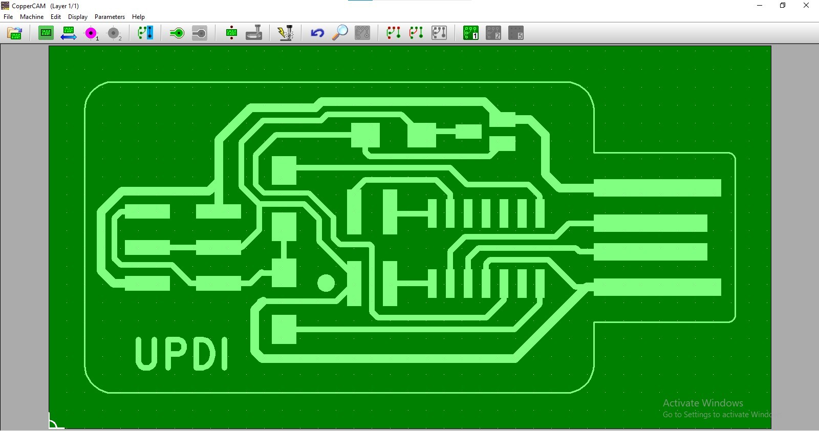
The software generates toolpaths automagically, with just a few parameters, and presents a simulation view of the result.
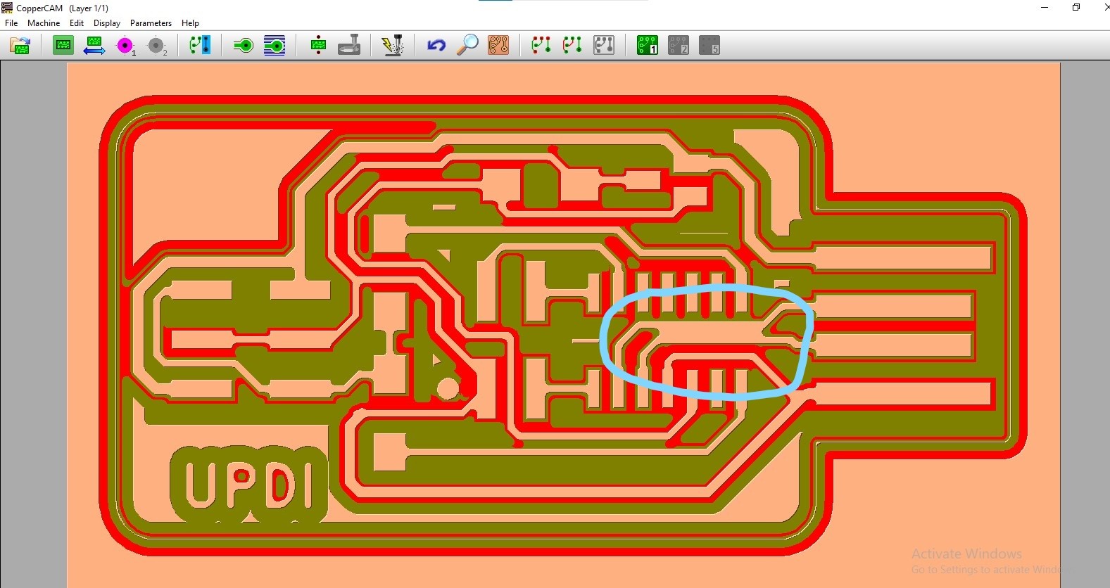
The automagic does of course fail sometimes, as can be seen, these particular traces are too near each other, and the software won’t cut them.
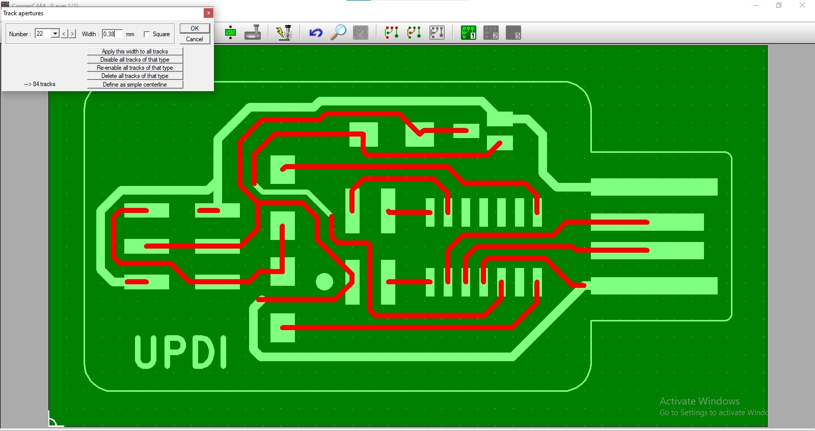
Luckily, this was easily fixed by ever so slightly narrowing the traces.
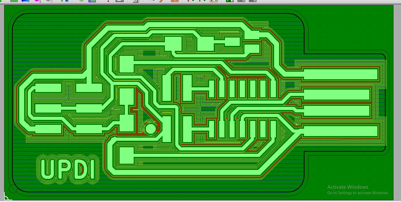
This is the Final toolpath. The milling machine does apparently not support tool change g-code, and instead spat out the tool operations as separate files. It was however clever enough to lump the hatching and cutting operations in the same file, as those are done with the same tool.
Off to the mill! The PCB is attached to the base using double sided tape. The mill is zeroed in the xy-axes by eyeballing, and in the z-axis by manually setting the tool in the chuck to rest on the PCB surface. The top level is thus the zero coordinate, traces are milled at -0.1mm and the board is cutout at -2mm.
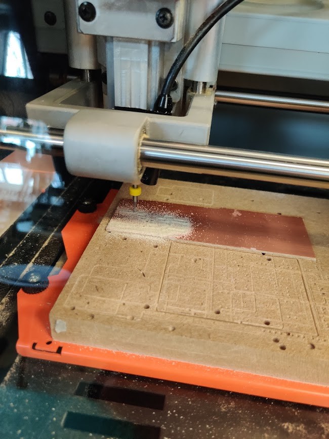
During milling, I noticed that i need to tighten the chuck more. If the bit was too loose, it would get pushed upwards, and cut too shallow. Fortunately, i could simply readjust the bit and run it again to get the desired results.
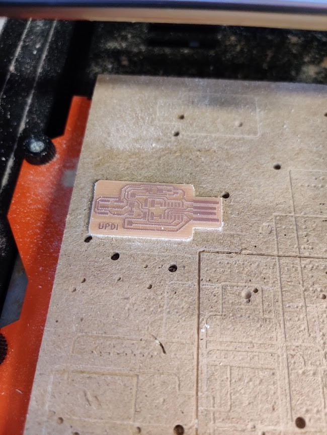
The final board looks really nice! Hatching with the flat mill worked resulted in a very nice surface. The traces are quite wavy up close, I assume that a more sturdy machine would mitigate this effect.
Off to soldering
Soldering
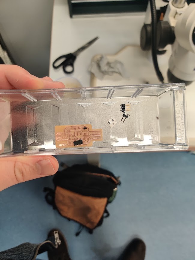
The programmer needs the following components
- 1x 1μf capacitor
- 2x 4.99kΩ resistor
- 1x 3.3V regulator
- 1x D11C microcontroller
- 1x 2x2 Pin header
- 1x 2x3 Pin header
There is a really nice online BOM available.
Unlike throughboard components I’ve used before, these are surface mounted or SMD type. SMD means that the parts are soldered directly to pads on the board surface.
FOr my soldering, I wanted to test something new. Fablab had some soldering paste in stock. Compared to regular solder, which comes in the form of solid wire, the paste is liquid and applied with a syringe. It can then be heated with a hot air gun, until it melts, and magically turns first into liquid and then into solid metal
The paste worked really well for the D11C chip. The chip, with it’s 14-pins would have been quite a pain to hand solder. I used paste for the other components as well, but in simple cases I’d almost recommend normal soldering, since that will probably give a stronger bond.
The board didn’t work immediately after soldering. First off, I had made the idiot mistake of using 5Ω resistors instead of 5kΩ… Oops. While fixing that, I accidentally caused a short circuit, and when fixing that I had a bad connection through one resistor. But on the third try, the board worked!!
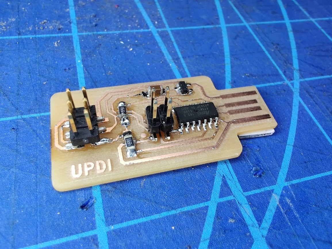
Finally, some hero shots of the board. Everything is a bit crooked, but the main thing is that it works!
Many of my soldering issues were due to solder shorting wires they shouldn’t. I noticed that we were provided with a soldering mask as well. I wonder if I could make one with 3M-1 and the vinyl cutter? Will have to experiment…