4. Computer controlled cutting
This week is focused around Computer controlled cutting, specifically laser and vinyl cutting.
Vinyl

I’ve used vinyl cutters for several years, but the lecture about their use was really interesting. For instance, I never realized you could make flexible circuits with them.
At the intro session we made a simple circuit board with the 3M1/Cu method. The process is quite straight forward. The thin copper layer is first glued to a substrate of 3M1, that keeps it from tearing in the cutter. Then it is weeded as usual (the copper is quite hard to remove though!)
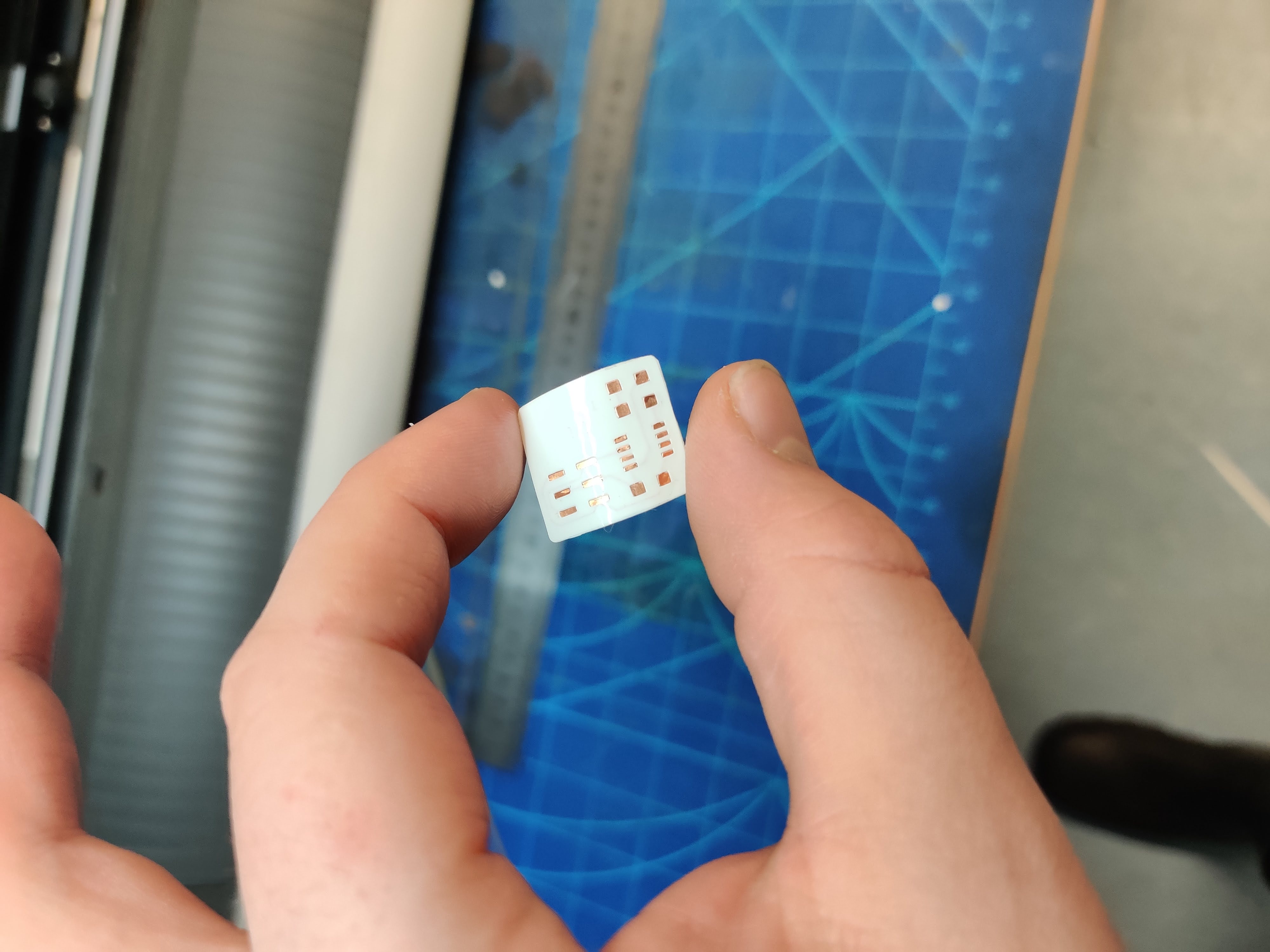
I was impressed by the fineness that the cutter is capable of making. I also tested soldering to the circuit, and the solder held well… A bit too well perhaps.
The traces detach quite easily, especially when attached to something, such as a soldered component.
Therefore, a top mask is probably quite important for the project, both for protecting the traces, and ensuring their attachment. I think the traces can be designed to “balloon” around the attachment points, thus giving the mask more area to stick on to. Definitely something to take into account.
I actually have a possible use for precisely that technology.
I have been experimenting with incorporating LED buttons to my student band uniform. My current solution uses silver laced conductive sewing thread. That solution however is ill suited for the hight-wear environment, and breaks all the time. While the thread is fairly easy to fix, it’s clearly not a good solution. Also, the thread has such a high resistance that the LEDs are starving or power, and the wiring resembles a ring circuit.
A flexible circuit could be the solution. Perhaps I could make a substrate that attaches to the front of the uniform with velcro. That way, the entire electronics module could be removed for maintenance. In general, modularity is never bad.
With the sewing thread i had a hard enough time just trying to keep the V and GND leads from shorting. With the substrate however i could not only skip that problem, but perhaps integrate data lines for addressable LEDs.
I drafted two general ideas using diagrams.net:
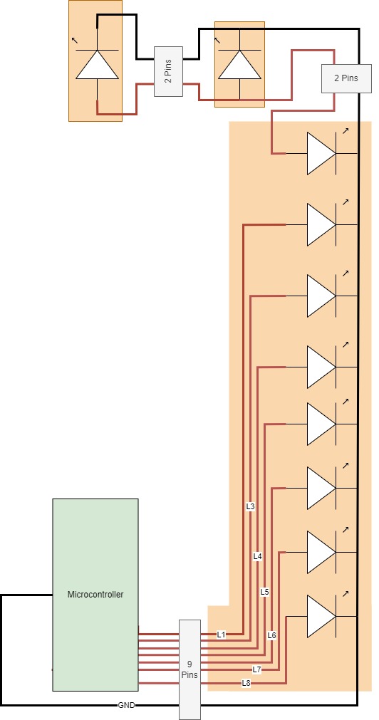
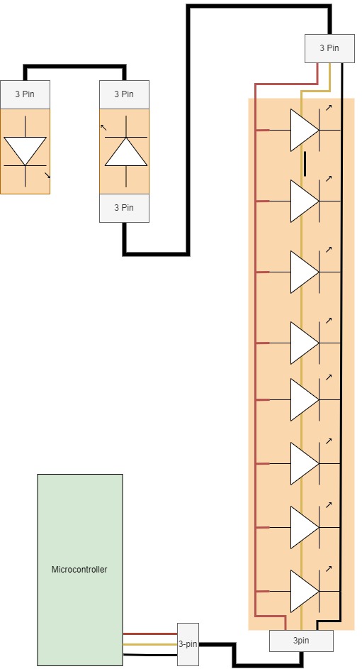
The first has parallel controlled leds, whereas the other uses an unified data line for them all.
There are advantages and disadvantages to both solutions. Addressable leds are apparently quite cheap these days, so i’m inclined to go for that approach. I wonder if the LEDs should be in parallel or series?
Anyway, that might become it’s own project.
For now, I might have a good vector job for the machine
We have this skating store in Finland, called Ponke’s
![]()
I’m no skater, but I had this meme idea, behold!
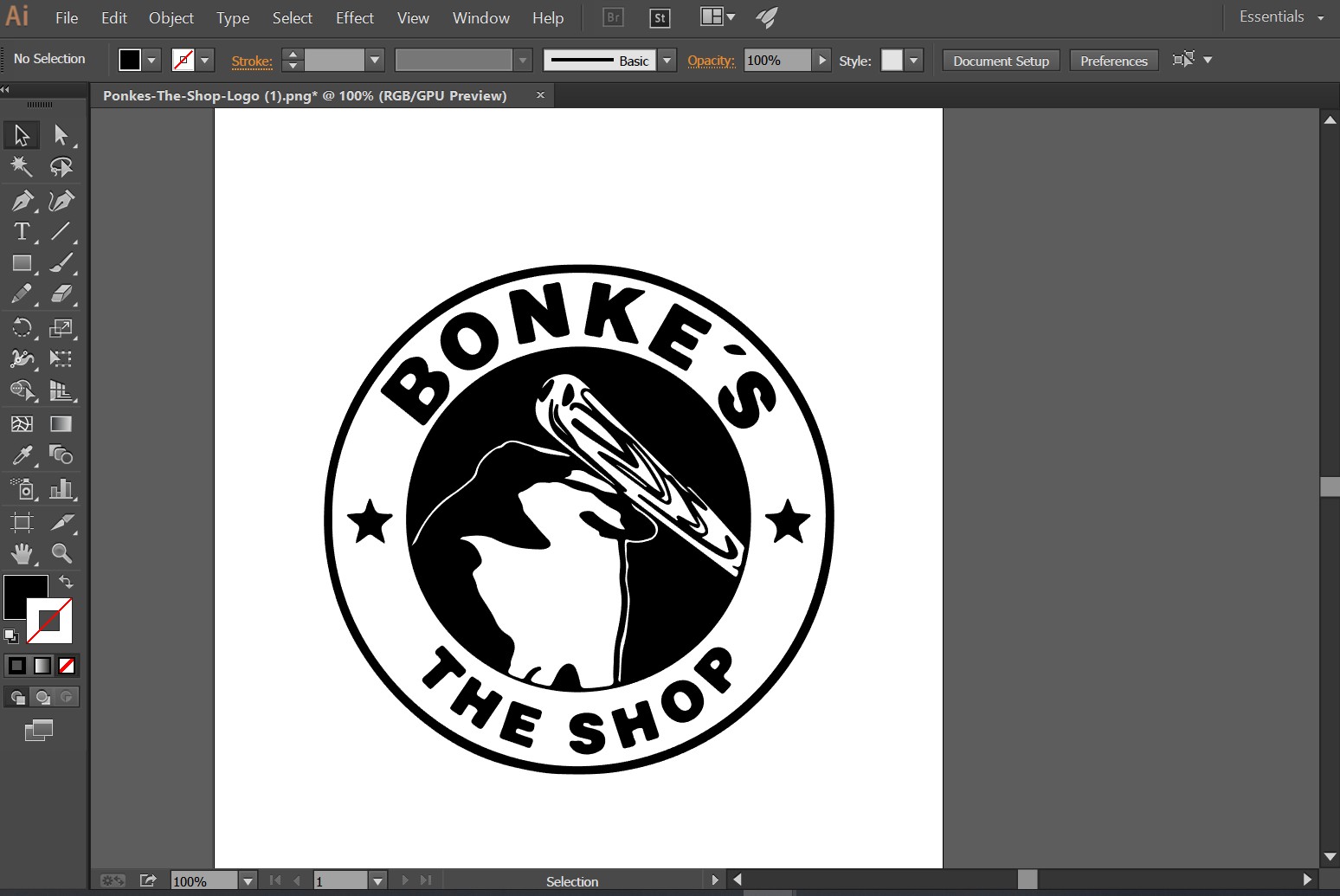
I could make it into a sticker or vinyl. It’s very dumb :D
Original editing was done in photopea, vectorisation in Illustrator.
Results
I did a very quick first pass on with the vinyl cutter.
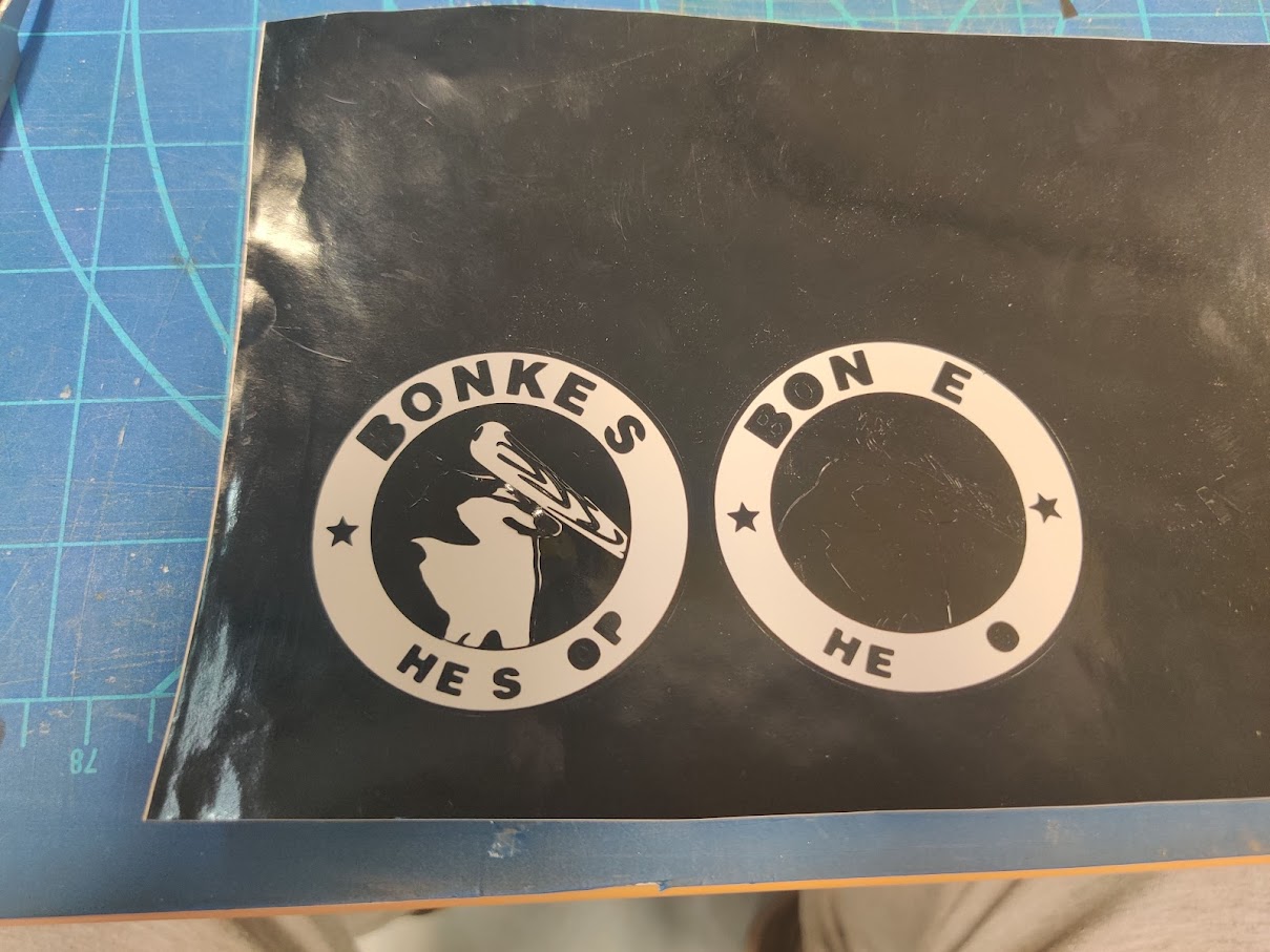
As you can see, results weren’t ideal. Perhaps the scale (70cm diam) was too small. Also cut weight could be increased, as it seems the vinyl was sticking quite heavily.

A more succesful project are these vinyl stickers with orchestra logos I’ve been making for sunglasses. Visibility is of course drastically reduced, but what wouldn’t one do for style?
Laser
THe laser cutter cuts and engraves material using Frigging lazors!

New laser!
THere was good news at the lab when I visited.
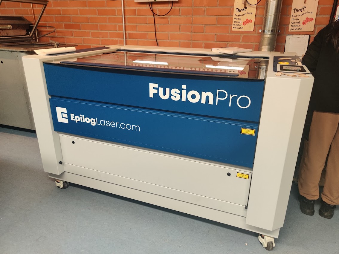
This monster has arrived. The new laser cutter with all the bells and whistles. 80W laser, 1200x900mm cutting area, image based cut positioning, oh my!
Operation is incredibly simple, even compared to the old machine. The software is very intuitive, and materials settings can be loaded straight from the cloud.
How to use laser cutter:
IMPORTANT
The laser cutter is evil and will try to burn your house down. Do not leave laser cutter unattended. Also make sure you know where fire fighting equipment is, specifically fire blanker and CO2 extinguisher.
Little flames are fine. In case of big flames, kill power. If fire doesn’t go out by itself, flood the machine with CO2.
10+ simple steps of laser cutting
- Use access key to enable power
- Turn on machine
- Turn on ventilation
- Insert workpiece in machine
- Print vectors and rasters to epilog engraver. CutStudio should open up.
- Position job using camera system, select appropriate cut&engrave settings
- When satisfied, send to JM (Job manager)
- Quick print from job manager. FInd job on printer touchscreen
- Ensure job placement with outline trace mode.
- Just Send It. Pause/abort operation if necessary.
- Wait for fumes to clear before opening lid.
Laser Group assignment
For the laser group assignment,
we measured the kerf of the machine:
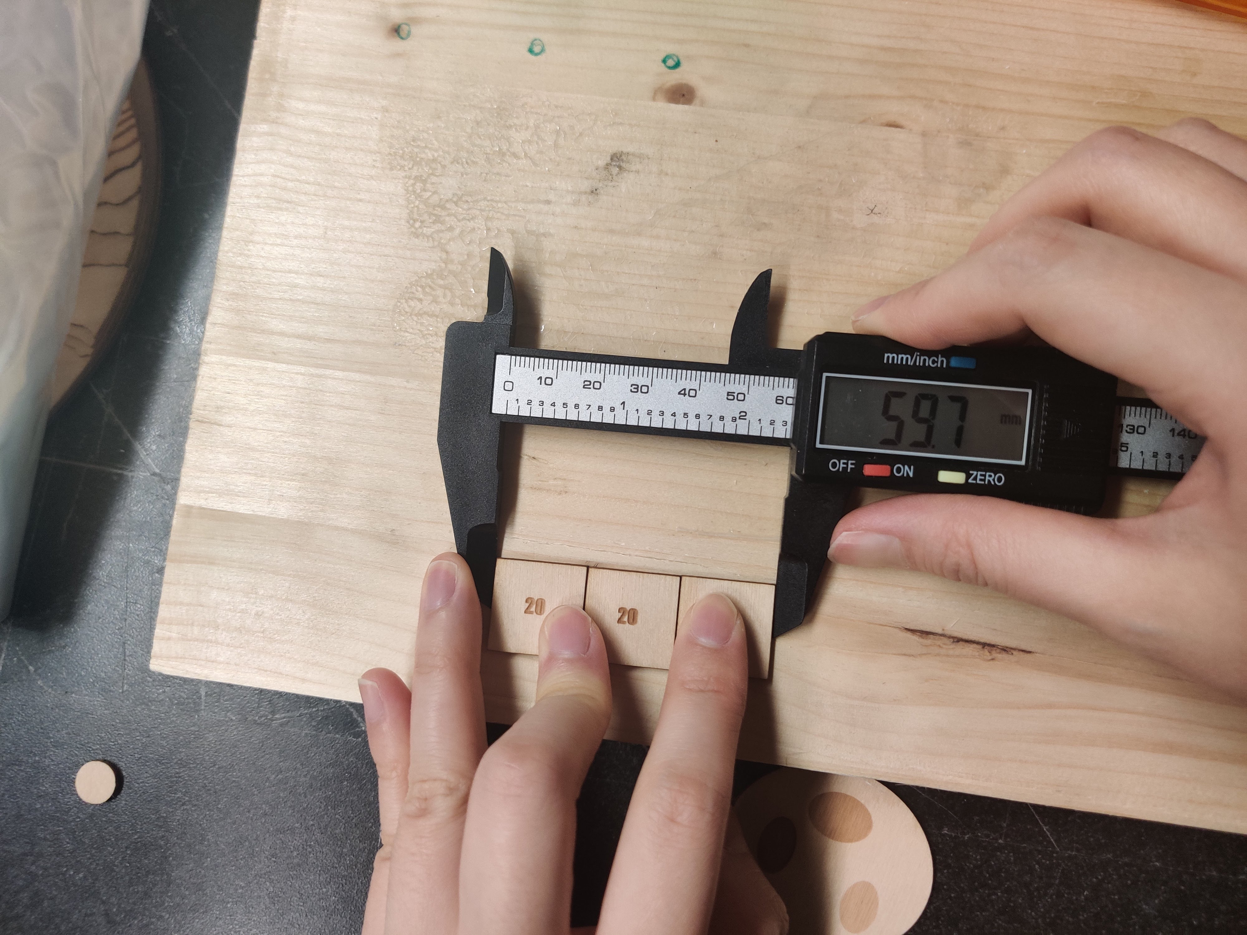
Three 20mm squares work out to 59,7mm. That makes the kerf 0.1mm.
The default settings for 2-3mm plywood are too fast, speed needs to be reduced from 12% to 10% for clean cut. Acrylic settings work well.
Individual assignment
For the laser I’ve prepared a couple of joint test pieces in Inventor.
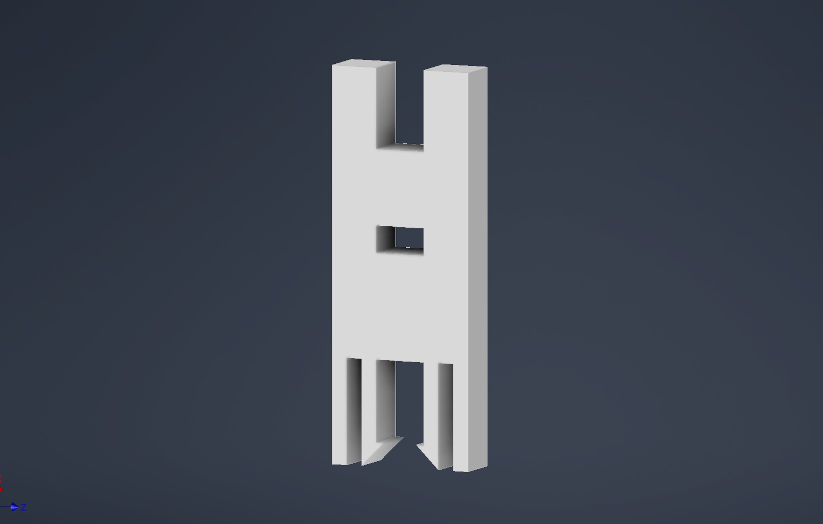
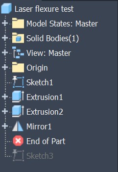
The model tree is quite simple, I sketched a half-piece and mirrored it to form the complete object.
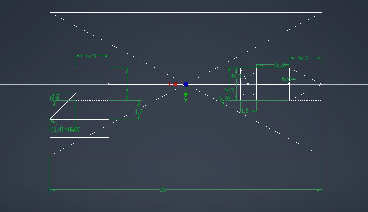
The first one is a simple snap flexure, that slots into itself.
The second one is also snap flexure, but for an outside slot.
The models use two parameters, M and O. M is material thickness, and O is offset. This should let me experiment both with different material thicknesses and tolerances.
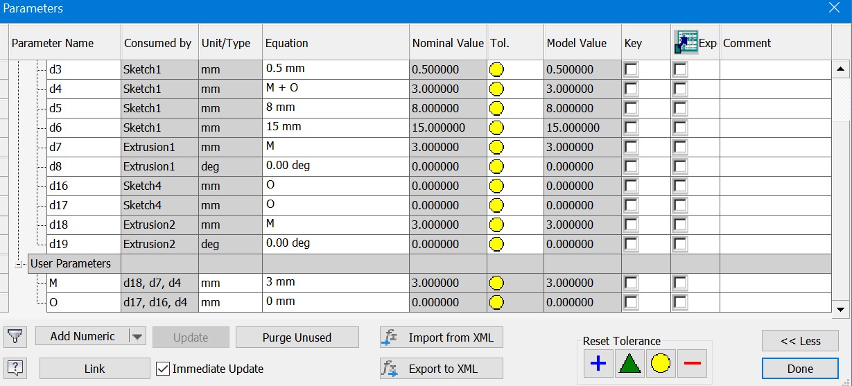
Inventor has a nice feature called block library, which lets one save sketch features. I commonly use that at work for logos, valve profiles etc. Once o figure out a good connector, I can make it into a block and easily integrate them elsewhere.
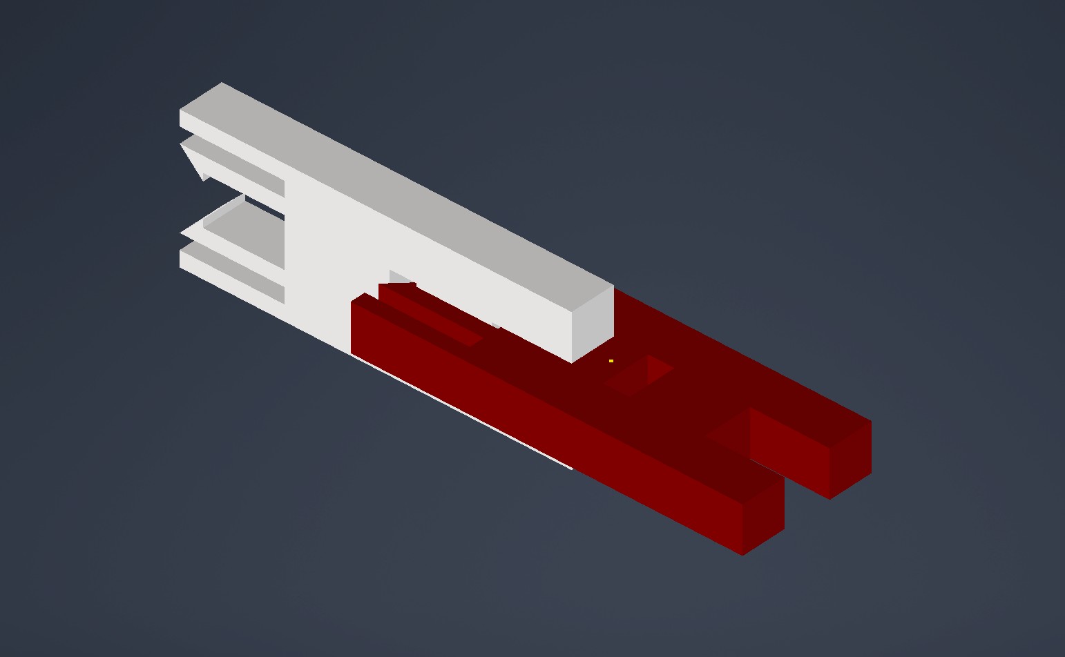
I also realized that I can quite easily modify my laser flexure to accept multiple kinds of attachment:

With a bunch of these I might be able to assemble something, like Legos!
I initially tried 3mm plywood, but the small details would get charred, Also the 1mm features were too thin, and broke easily. I thus adjusted the parameters a bit, and increased min. wall thickness to 1.6mm. I also switched to acrylic, which rendered small details better than wood. A 0.1mm kerf offset resulted in a nice fit.
With the waist, the end result looks like some kind of insect, so i named it Bug Block.
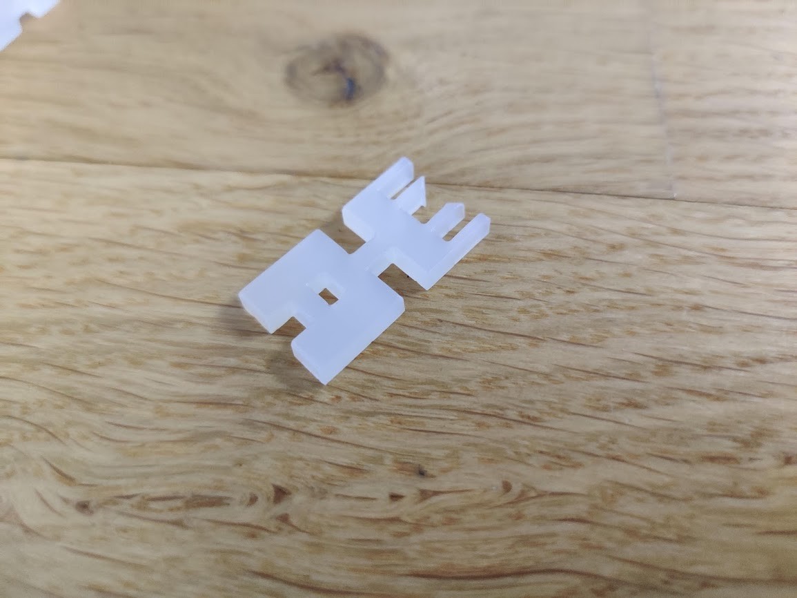
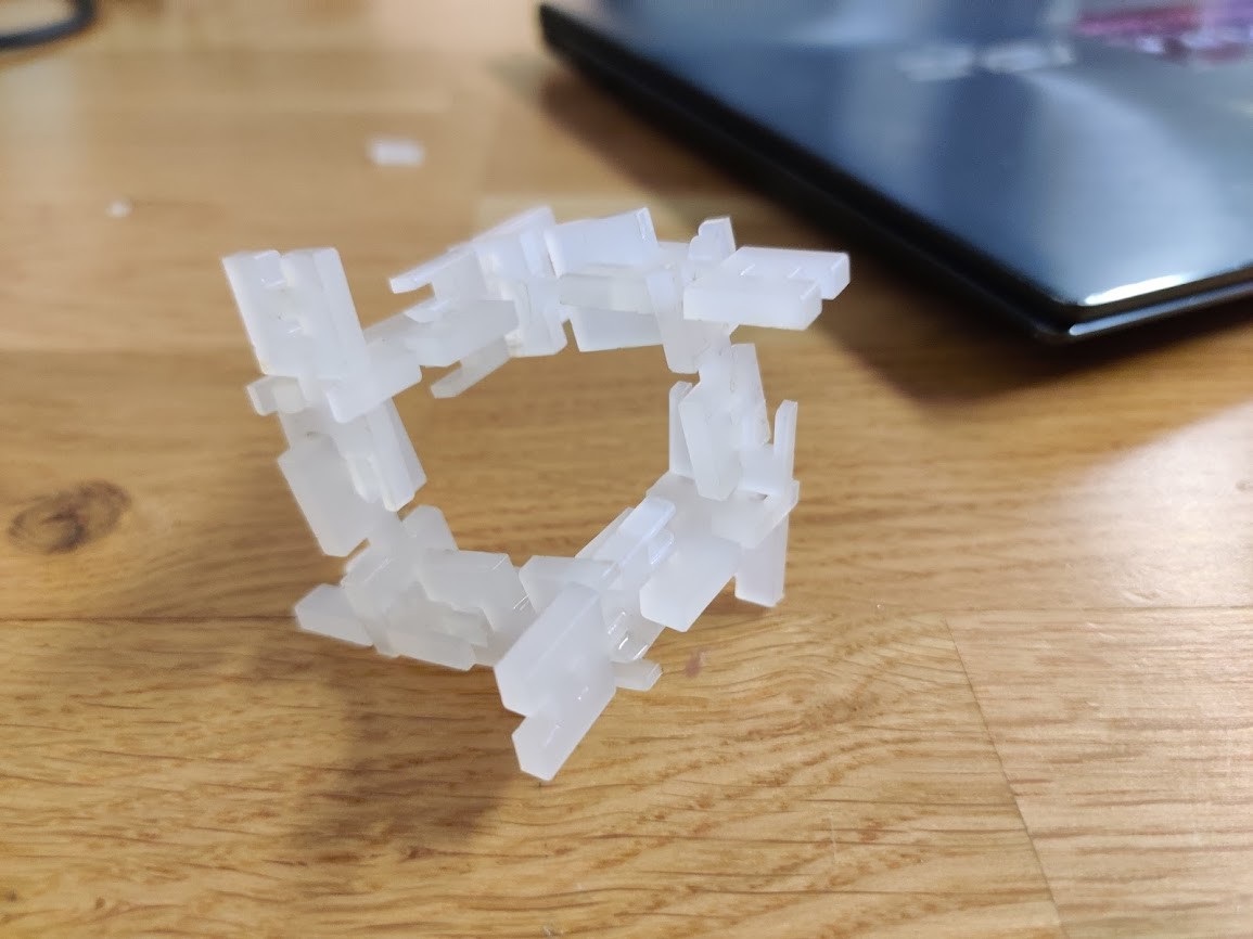
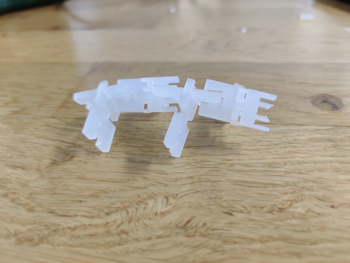
the bug blocks can be assembled in different configurations. They stick together quite well!
This week’s design files can be found here