group assignment:
compare the performance and development workflows for other architectures
#ArduinoMEGA#NucleoSTM32#ArduinnoIDE#Mbed
individual assignment:
read a microcontroller data sheet program your board to do something, with as many different programming languages and programming environments as possible
Group assignment for this week is to compare the performance and development workflows for other architectures. Our group (Zhengya Gong, Yazan Barhoush, Noora Nyberg and Xinhui Hu) tested STM32 Nucleo-64 development board with STM32F303RE MCU and Arduino Mega board. For the both boards we used LED blinking test, as the LED is the simplest peripheral output.
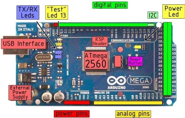
Arduino MEGA 2560 is designed for projects that require more I/O pins, sketch memory and RAM than Arduino UNO, it is the biggest Arduino microcontroller. The Mega 2560 board can be programmed with the Arduino Software (IDE).
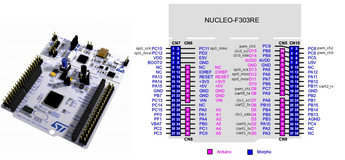
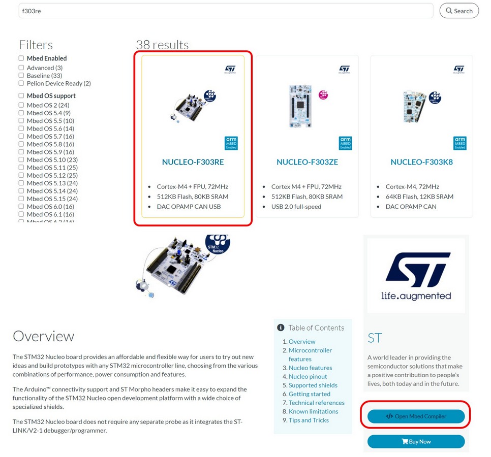
STM32 Nucleo-64 is a development platform with STM32F303RE MCU. Datasheet STM32F303RE. The STM32 Nucleo boards integrate the ST-LINK/V2-1 debugger and programmer. The
ARDUINO® Uno V3 connectivity support and the ST morpho headers provide an easy means of expanding the functionality of the Nucleo open development platform with a wide choice of specialized shields.
Arduino are the most popular boards for the begginers with a full functionality for the embedded programming. STM32 Nucleo boards, however, have the better performance in general, more inputs/outputs and debugging options available. But again, STM32 Nucleo boards don't have EEPROM for storing the permanent varibales for a system reboot, as the 4 KB internal EEPROM of Arduino MEGA.
The comparison table of the main features of the tested boards and performance:
Properties
Arduino Mega
STM32 Nucleo-64
Manufacture
Atmel Corporation
STMicroelectronics
Microcontroller
ATmega2560
STM32 microcontroller in LQFP64 package
Processor
8-bit RISC processor core
ARM®32-bit Cortex®-M4 CPU with FPU, RISC
Architecture
Harvard
Harvard
Flash Memory
256 KB
512 KB
SRAM
8 KB
64 KB
EEPROM
N/A
4 KB
Operating voltage
5 V
2 to 3.6 V
Communication interface
54 Digital I/O Pins, 15 Digital I/O Pins with PWM, 16 Analog Input Pins, 4 UARTs
Up to 115 fast I/O Pins, Up to 5 USART/UARTs, Up to 4 SPIs
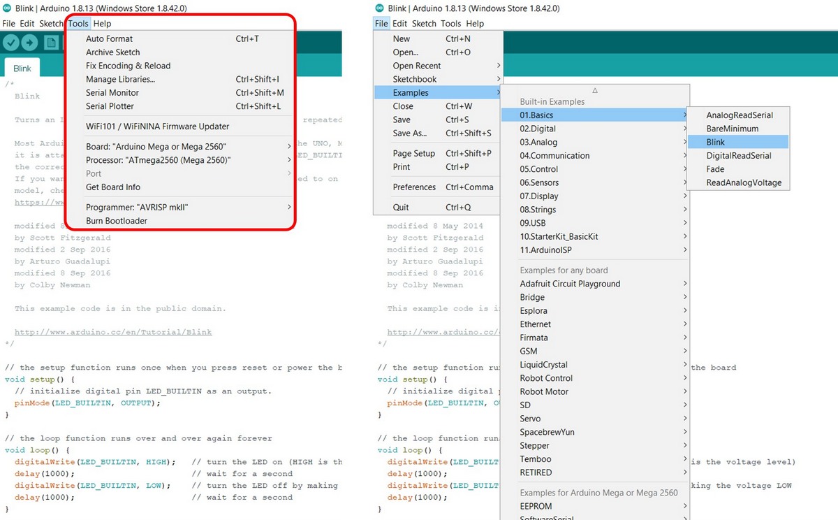
In Arduino IDE -> Choose Tools and port as follows below in the figure:
We used the simple sample sketch from Arduino IDE, which will make pin 13 LED on the board start to blink. File -> Examples -> Basics -> Blink Download sketch Blink test for Arduino Mega
Fig 1. Arduino IDE settings for programming the Arduino Mega board.
Fig 2. NUCLEO-F303RE board and pinout. Image credit
ATTINTY412 is a 8-bit AVR® RISC (Reduced Instruction Set Computing) architecture microcontroller. Some of the main features:
AVR® 8-bit CPU running at up to 20MHz
2/4KB In-system self-programmable Flash Memory
64/128B EEPROM
128/256B SRAM
Single Pin Unified Program Debug Interface (UPDI)
6 Programmable I/O Lines and 8-pin SOIC150
128/256B SRAM
Fig 1. ATTINY412 pinout
UPDI - Unified Program and Debug Interface
Programming and debugging is done through the UPDI Physical interface (UPDI), which is a 1-wire UART based interface using the RESET pin for data reception and transmission. Clocking of UPDI is done by an internal oscillator. (Features, Overview, Block diagram, etc. from p. 379)
Communication through the UPDI is based on standard UART serial communication (Universal Synchronous and Asynchronous Receiver-Transmitter).
Communication lines of USART are:
Receiver - RX (PA1) and the Transmitter TX (PA2).
UPDI can access the entire I/O and data space of the device
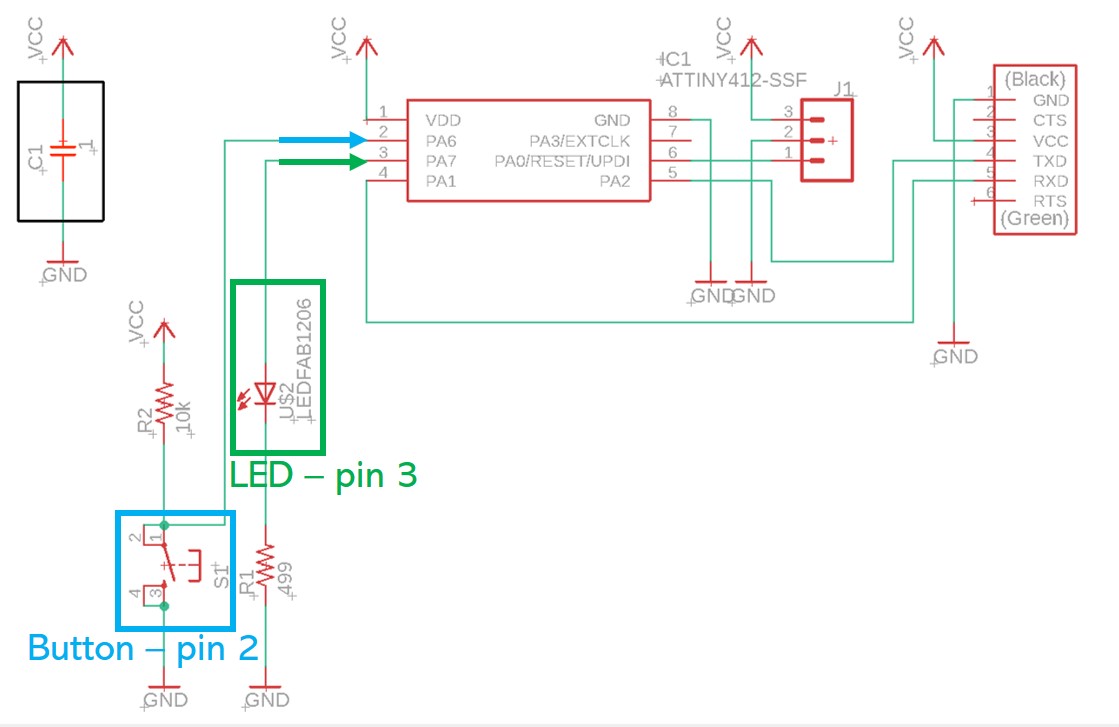
In my echo-board, LED is connected to PA7, which is in ATTINY412 is pin number 3
and the BUTTON to PA6, which is pin number 2.
For the beginners like me, Arduino IDE would be the best choice to start programming. There are many examples with comprehensive explanations available. I started with using programs, made by the students last year.
With this knowledge I'm ready to proceed:
Simply connect programmer with 3 pin female connector of the board
I took the Arduino sketch example from Arash's page, to make LED blinking the number of times the BUTTON is pressed.
I changed the pin's number for BUTTON and LED.
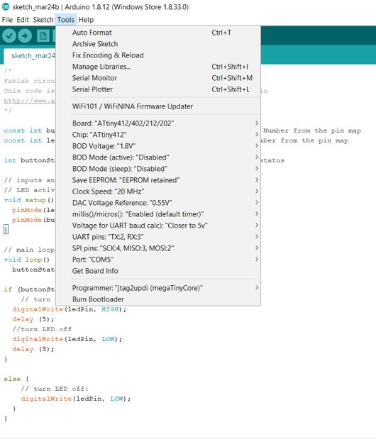
Settings in Arduino IDE:
Fig 3. Arduino IDE to upload the sketch on the board.
Unfortunatly, nothing have happened. Therefore, I decided to simplify the program, just to check if my LED works. I used the simplest available Arduino sketch:
void setup() {

  // put your setup code here, to run once:

  pinMode(3, OUTPUT);

}


void loop() {

  // put your main code here, to run repeatedly:

  digitalWrite(3, HIGH);

  delay(100);

  digitalWrite(3, LOW);

  delay(100);

}
Again, nothing happened, even though sketch uploading was successful. To ensure, that programming is happening, I tried the previous echo program with Putty, which worked. After I uploaded the new program, I checked Putty, and it stopped responding, meaning, that programming is happening succesfully. Eventually, HUGE THANKS to Gleb, and our intructor Ari, who sent us help just few minutes later, after I succeed with a programming.
The ISSUE is that the pinout of Attiny412 is different from the pinout in Arduino IDE megaTinyCore. This Gitlab page reports: "WARNING: On pre 2.0.0 versions of megaTinyCore, the UART defaulted to the alternate positions
This matches the megaTinyCore 412/402 Rev. - and Rev. A breakout boards below. In 2.0.0 and later, this is no longer the case! You must call Serial.swap(1) prior to Serial.begin() to move it to the alt pins (or connect your adapter to pins 0 and 1 instead of 2 and 3)."
Therefore, the pins in the sketch should be defined as:
Output LED pin number is 1
and the Input BUTTON pin is 0.
I'm trying the LED pin set to 1, and it works now!
Another example, when the button is pressed, the light is turned off:
// constants won't change. They're used here to set pin numbers:
const int buttonPin = 0; // the number of the pushbutton pin
const int ledPin = 1; // the number of the LED pin

// variables will change:
int buttonState = 0; // variable for reading the pushbutton status
int lastButtonState = 0;

void setup() {
// initialize the LED pin as an output:
pinMode(ledPin, OUTPUT);
// initialize the pushbutton pin as an input:
pinMode(buttonPin, INPUT);
}

void loop() {
// read the state of the pushbutton value:
buttonState = digitalRead(buttonPin);
// check if the pushbutton is pressed. If it is, the buttonState is HIGH:
if (buttonState != lastButtonState) {
if (buttonState == HIGH){
digitalWrite(ledPin, HIGH);
}
else {
digitalWrite(ledPin, LOW);
}

}
lastButtonState = buttonState;
}
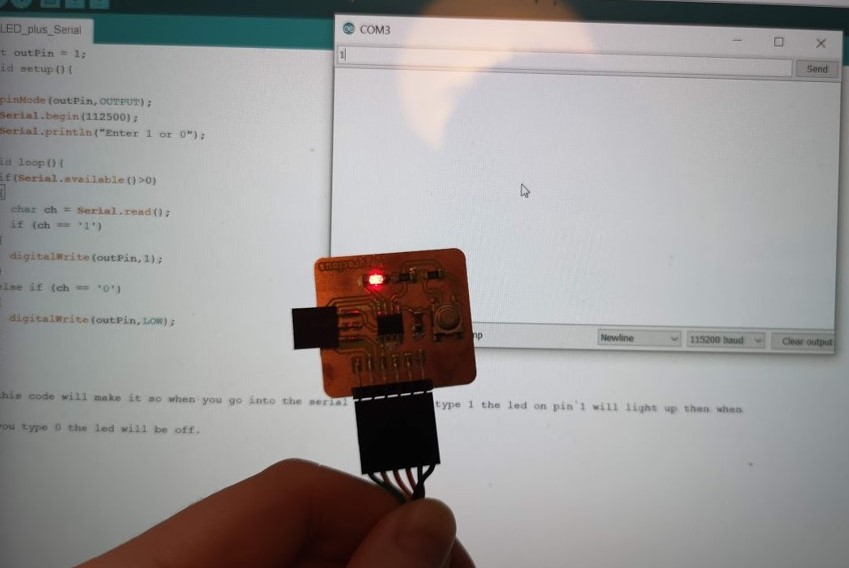
One more code, which joins the serial monitor with LED function: typing 1 in a serial monitor the LED will light up, and typing 0 with turn it off.
int outPin = 1;
void setup(){
Programming requiers not only coding knowledge, but also some extra datasheet reading for the electronics. Quite challenging, but starting with simple Arduino IDE examples and tutorials will ease the pain of embedded programming for the beginners.