LED brightness control with rotatory knob (potentiometer)
This week I was making the board to control the backlight for my final project. I plan to make a LED backlight, similar to one used in microscopes. Arduino kit includes a rotatory knob, which is a potentiometer. Basically, this knob provides a variable resistance, which can be read in Arduino board as an analog value.
Most of the environmental physical parameters such as sound, light, temperature etc. can be measured only in analog form. Therefore, to work with this data,
it is required to convert measurements from analog to digital data.
The Arduino Uno has a 10-bit analog to digital converter, or Analog to Digital Converter (ADC). The ADC is mapping the input voltage (up to 5V) to an integer value up to 1024, therefore dividing 5V by 1024 bits is corresponding to ADC resolution.
PWM (Pulse Width Modulation) is a technique for getting analog results with digital means. PWM is possible on I/O pins on the Arduino UNO: 3, 5, 6, 9, 10, 11 (usually maked with ∼). The pulse width is the time duration, when the signal is on, so varying the analog values is the result of pulse width duration. In the code below it returns a number between 0 and 1023 that is proportional to the amount of voltage being applied to the central pin, between the VCC and GND.
analogWrite() writes an analog value (PWM wave) to a pin. In the code below it returns a number between 0 and 1023 that is proportional to the amount of voltage being applied to the central pin, between the VCC and GND.
analogWrite(ledPin, val / 4); // analogRead values go from 0 to 1023, analogWrite values from 0 to 255
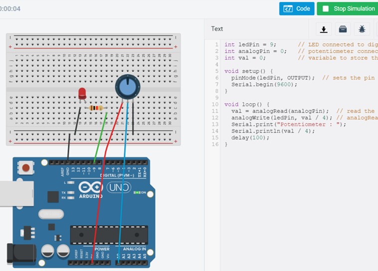
I have modified Example code, which sets the output to the LED proportional to the value read from the potentiometer.
- LED pin to digital pin 9 (OUTPUT)
- 220 ohm resistor
- Potentiometer to analog pin A3
Fig 3. Curcuit model with Tinkercad.
Arduino sketches:
NeoPixels
Instead of using the number of LEDs, I decided to use NeoPixels as a backlight for microscopic samples. The brightness of about 8 NeoPixels controlled with potentiometer shoud satisfy my requirements.
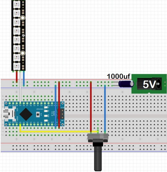
Controlling the NeoPixel is described in many tutorials (tutorial). Every NeoPixel LED has 3 contacts: Power, Data and GND. They are connected via copper base in one strip. Wiring basics are the same as I described before for the simple LED brightness control - potentiometer is connected to analog, and Data of Neopixel to any digital (PWM) pin.
Fig 3. Wiring of NeoPixel and potentiometer with Arduino Nano
For operating the NeoPixel strip there is a special library for Arduino IDE Adafruit_NeoPixel.h, it just have to be included in the sketch. Then the LED_COUNT needs to change with the total number of LEDs Arduino is going to control and LED_PIN is to describe the LED data pin on Arduino.
Backlight brightness control with ATtiny44
After the global corona lockdown we finally can return in Fablab to continue our work. One of my Final Project parts is the backlight for the microscopic sample. I plan to make a separate board with ATtiny44 chip controlling the brightness of NeoPixels.
The main ATtiny44 features from the datasheet:
- 14-pin SOIC, 12 programmable I/O lines
- 4K Bytes of in-System Flash program Memory
- Operating voltage: 2.7 - 5.5V
- Universal Serial Interface
- 8 MHz internal calibrated RC oscillator
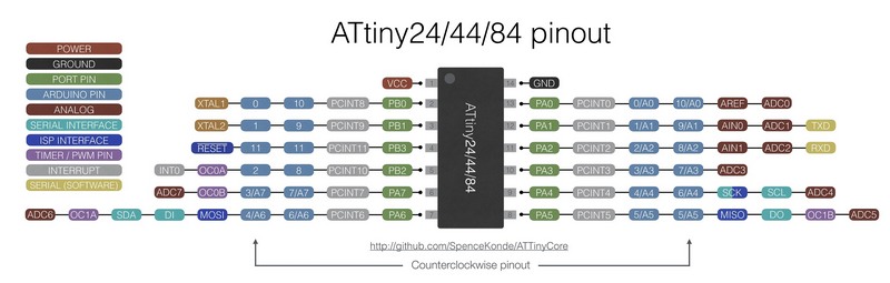
Fig 3. Pin Mapping of ATtiny44 from ATTinyCore Github page.
Checking the documentation of the last year students I found that they used ATtiny44. Particulary, Gleb used Attiny44 to control NeoPixels. I was using his documentation to make the Backlight board's schematic and layout. NeiPixel LEDs can be controlled by connecting them to the PWM pin, according to the pinout of ATtiny44 pin PB2 (physical pin 5).
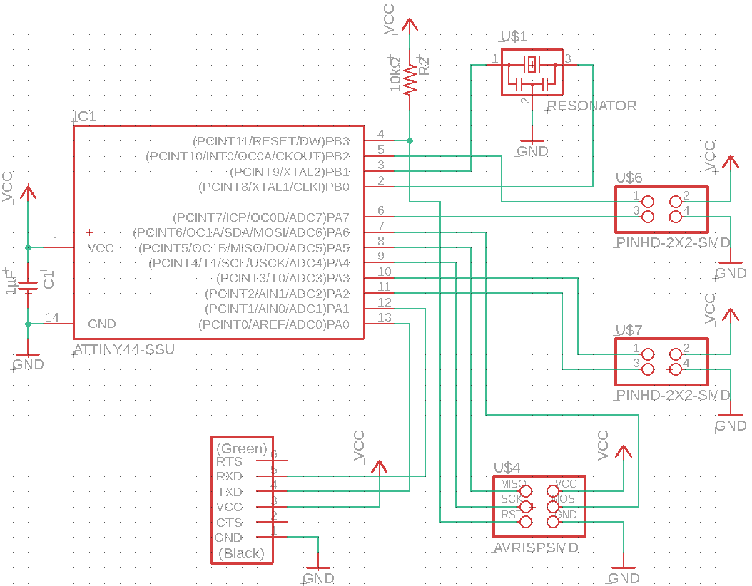
Components
ATTINY44-SSU x1
FTDI-SMD-Header x1
Male header 2x2 SMD x2
Male header 2x3 SMD x1
20 MHz resonator x1
Resistor 10 kΩ x1
Capacitor 1uF x1
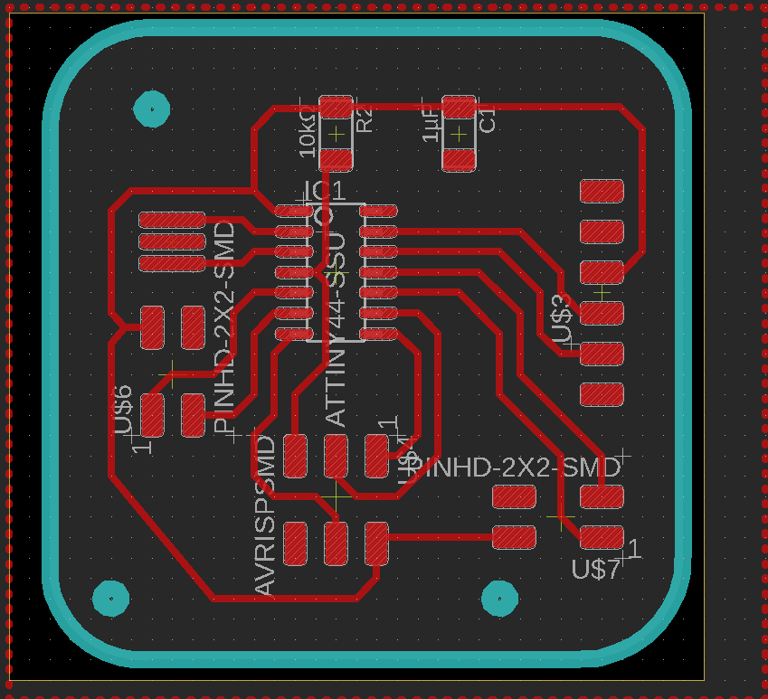
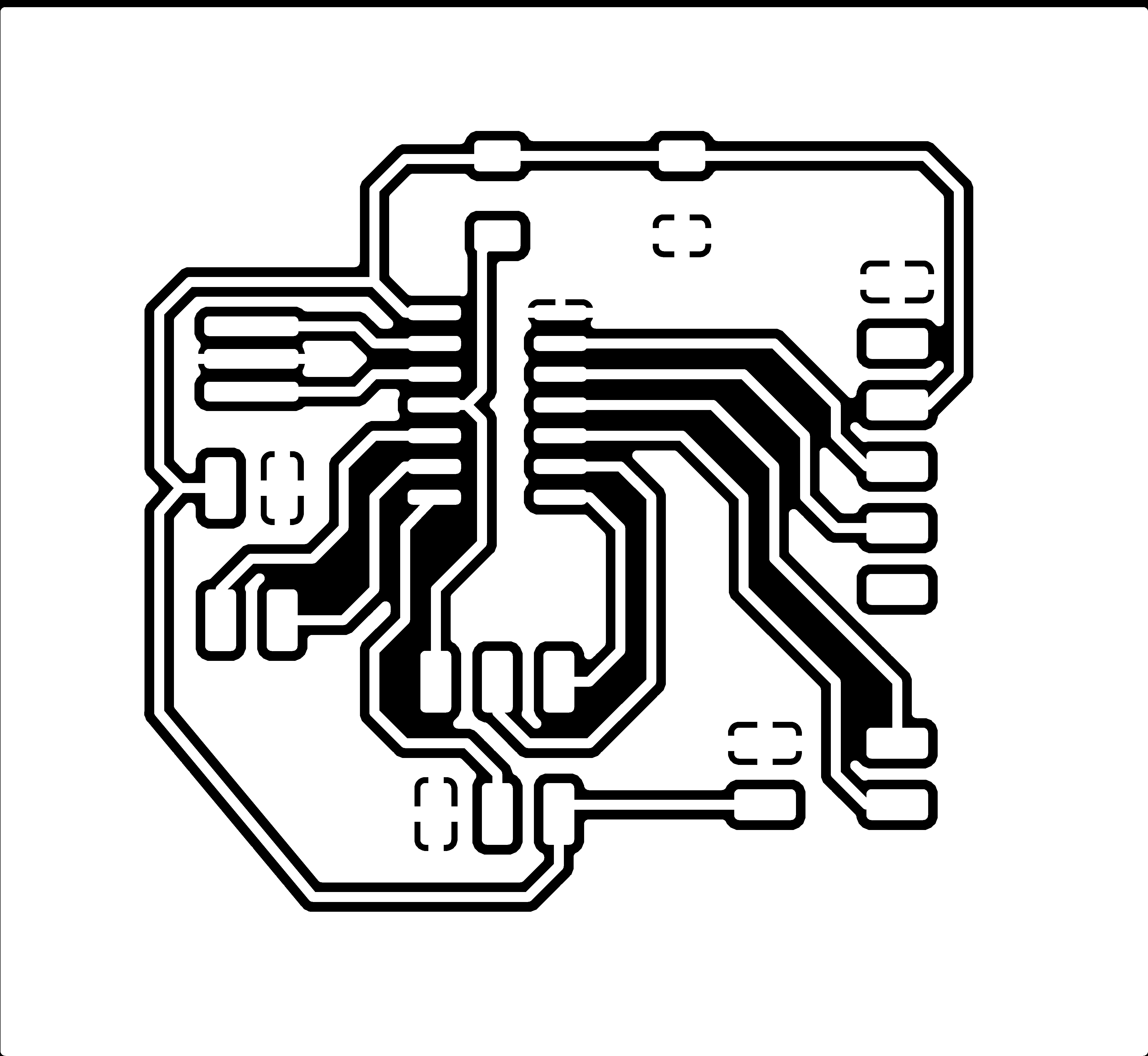
Fig 3. Backlight PCB schematic and layout.
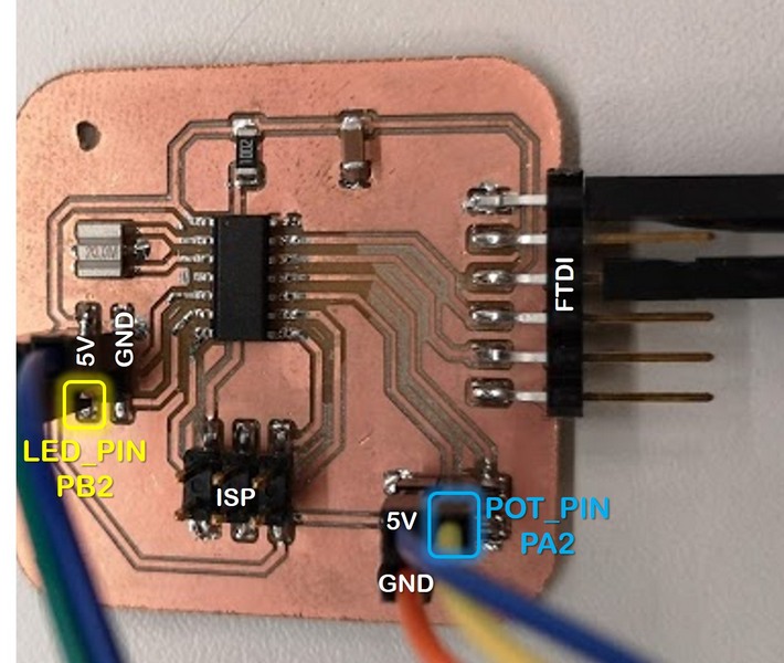
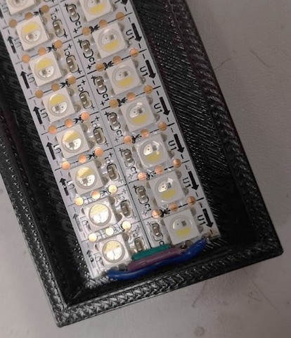
Fig 3. Backlight PCB after soldering.
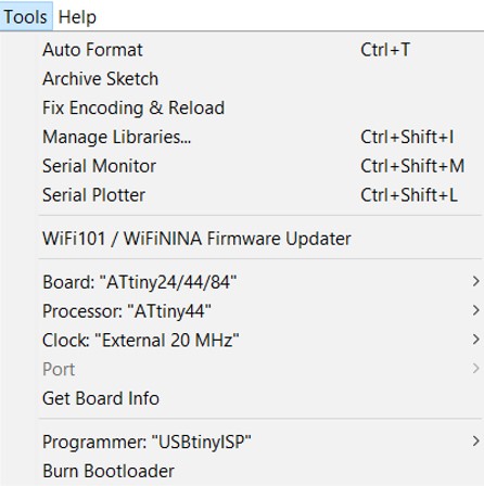
Programming steps for Attiny44 with Arduino IDE are well described on this page .
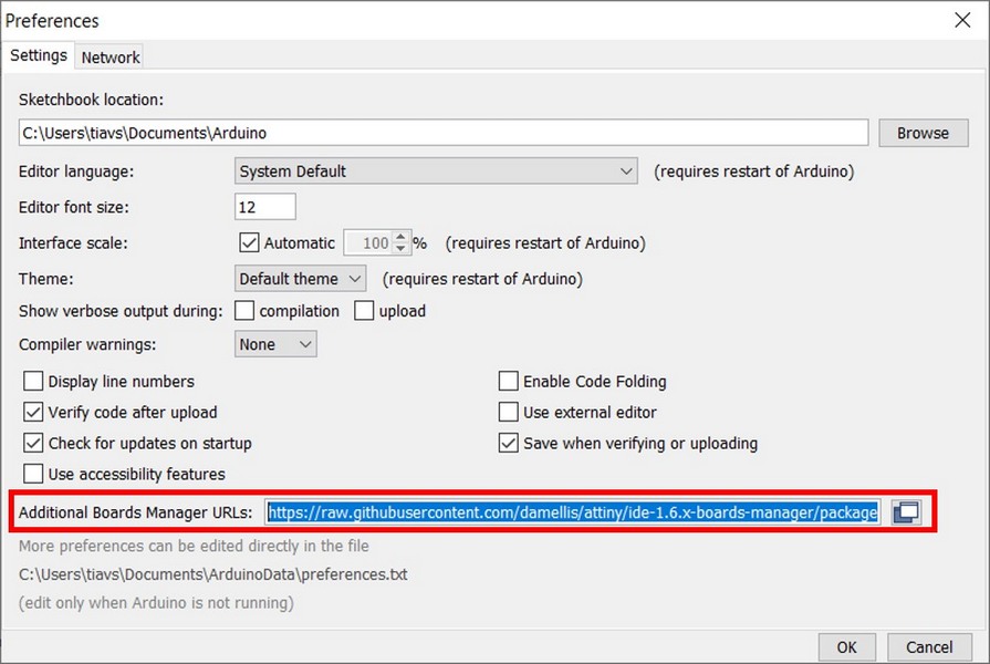
Same, as we did programming of the Attiny412 on Electronics design week, the programming of the Attiny44 should start from the downloading installing the board manager:
Preferences > “Additional Boards Manager URLs” > Paste the following URL https://raw.githubusercontent.com/damellis/attiny/ide-1.6.x-boards-manager/package_damellis_attiny_index.json
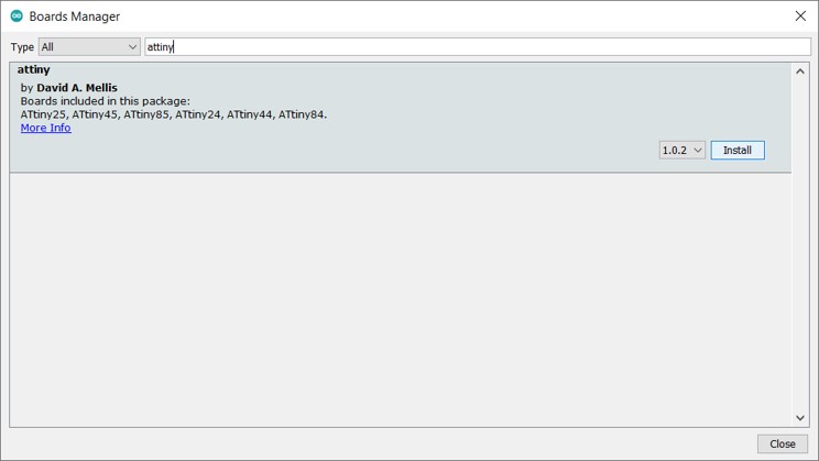
Tools > Board > Board's manager
I used USBtinyISP programmer like this one (more). ISP cable is connecting the ISP headers of the programmer and backlight board: MISO, MOSI, SCK, RESET, VCC, and GND of the programmer to the corresponding pins on the ATtiny. Both FTDI cabels from the backlight PCB and programmer are connected to USB port. FTDI here is powering the programmer.
I connected 2 stripes by soldering small wires between the contacts. and Before uploading the code, I modified the code for 20 NeoPixels.
For some reason only 15 LEDs would lighten up, however, same code worked for Arduino board, I still don't understand why. After long time testing the contacts the board just stopped working completely. Then I just fabricated the same new board, and used the code for 18 LEDs. Continuation is on the Project Development page: Backlight board ATtiny44 and Programming.
Files for the Backlight PCB:
Reflection
This week I made a small contribution to my final project by controlling the brightness of NeoPixels, which will be used a backlight for the sample.
