Computer-Aided Design
- Model (raster, vector, 2D, 3D, render, animate, simulate, ...) a possible final project
GIMP#Inkscape#Blender#Autodesk 360
- Compress your images and videos, and post it on your class page
Game bar
GIMP#Inkscape#Blender#Autodesk 360
Game bar
Raster grapics (bitmap / pixelmap images) are comprised of mapped bits. These images are resolution dependent - resizing the raster graphics to a larger image will cause the apparency of the square pixels. However raster imaging is preferable way to represent photos with lot of colors and transitions between them.
There are plenty of powerful tools for the raster 2D design, however since I used GIMP before, plus it is open and free, I stayed with this software.
During my PhD research I performed scanning electron microscopy (SEM) imaging of red blood cells with nanoparticles. SEM images are coming in grayscale regime, to color them, I used GIMP. All these images are actually presented in the carousel of the main page of my website. Steps to color grayscale image in GIMP: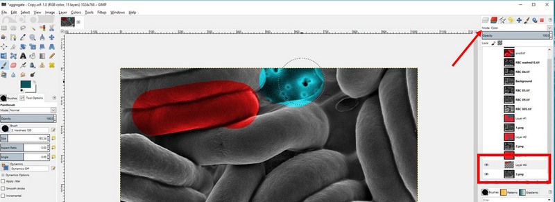
Fig 1. Coloring black and white SEM image with GIMP
Vector grapics unlike the raster are resolution independent - despite zooming the image the resolution will not change, and no pixelated artifacts will appear. Vector images are based on mathematical expressions and use points, lines, curves and polygons to represent images.
Starting working with Inkscape I have created the image, kind of logo of Optical tweezers technology. There is a nice tool to work with the text:
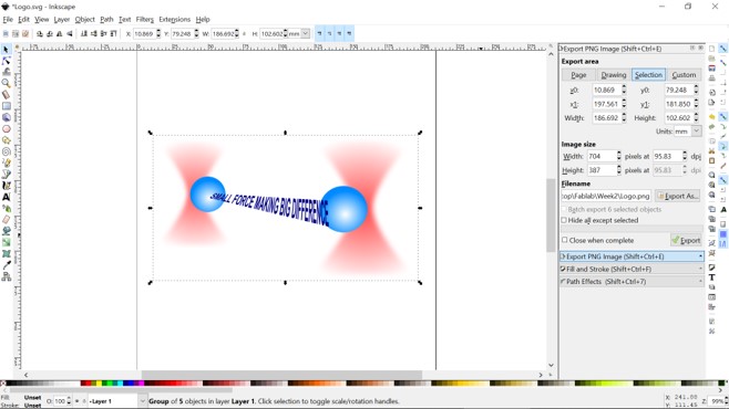
Fig 2. Drawing in Inkscape
Since we will use laser cutting, I thought it will be useful to check how to design the objects for that purpose. I went through the simple tutorial with the detailed step by step explanations on the object drawing from the start. This one is useful to understand the main idea of creating the parts for your cut.
There are two more ways to design the objects. At first, in this tutorial I found the online Boxmaking tool Boxes.py - the box generator written in Python, with many types of boxes, which can be modified online in the settings menu.
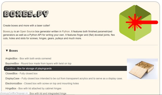
Fig 4. Boxes.py menu
Besides, I found, that TabbedBoxMaker also can be installed as an extension for Inskape from Github as an open source plugin. To intstall it I have Downoad ZIP from the Github, then I opened the archive and copied files boxmaker.inx, boxmaker.py and schroffmaker.inx in to a folder extensions in the Inkscape directory. I started Inkscape and the new extension can be found Extensions>Laser Tools>Tabbed Box Maker.
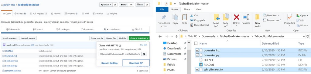
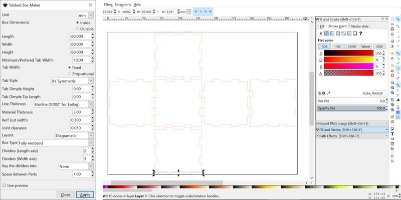
Fig 5. Installation of the Inskape extension from TabbedBoxMaker and generation of simple box
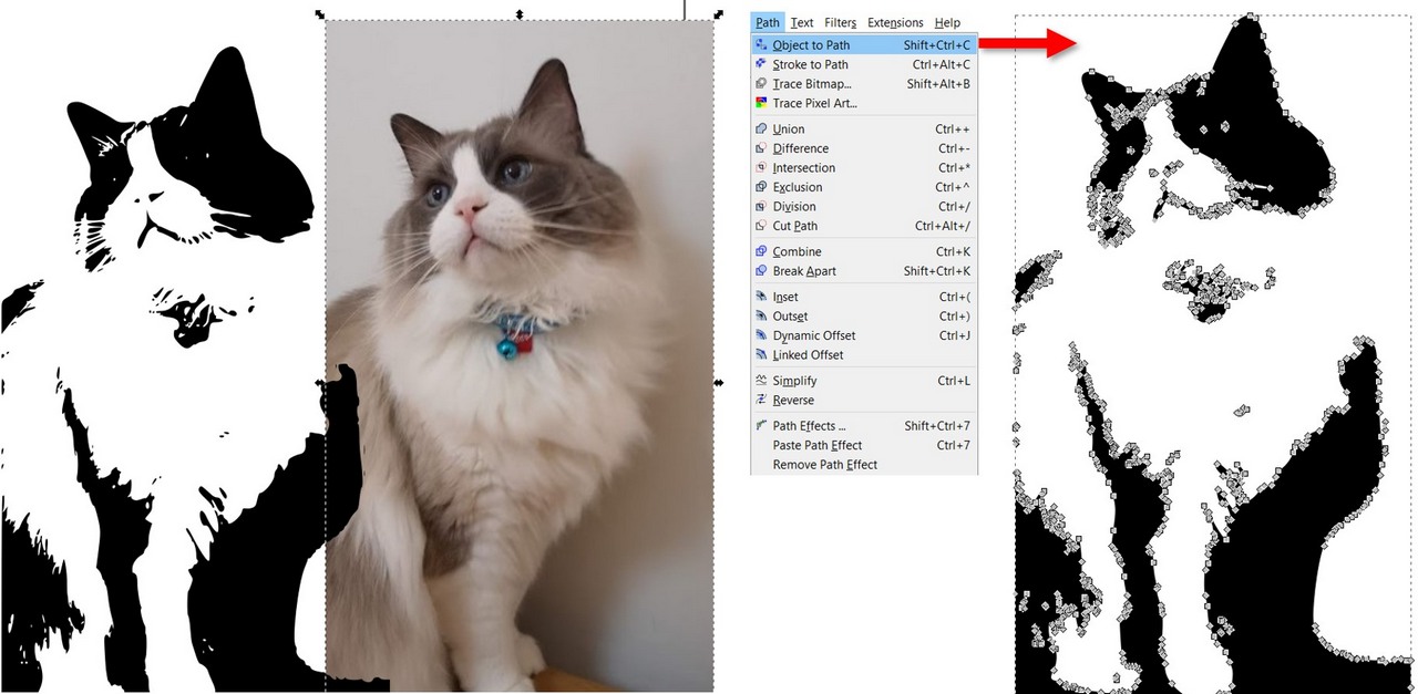
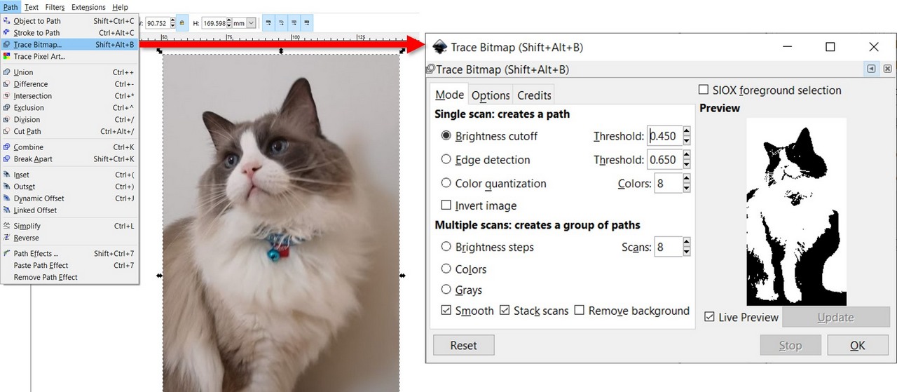
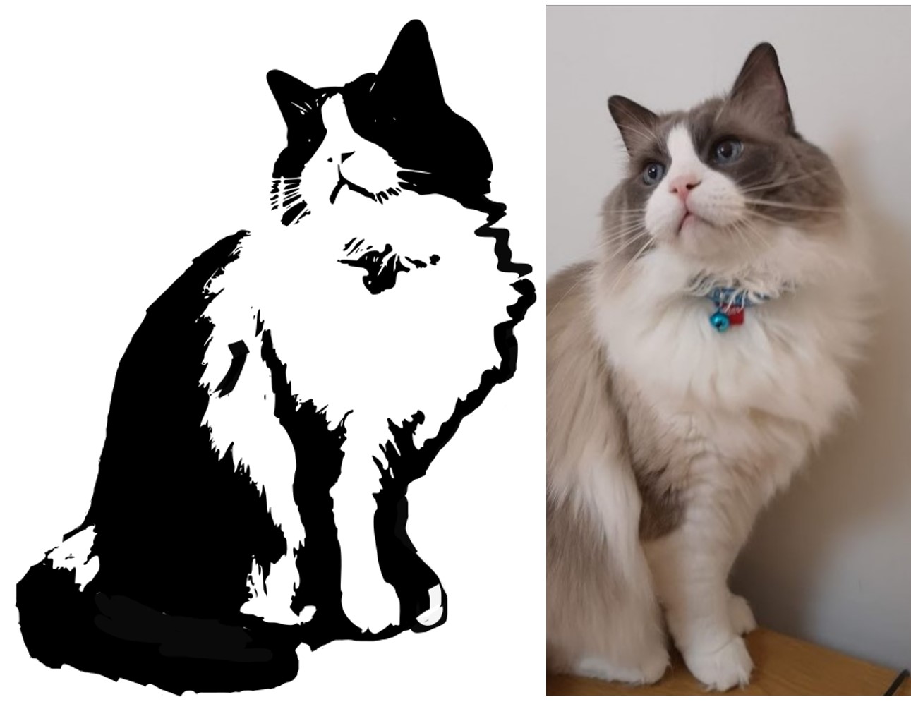
Fig 6. Processing the image in Inkscape
Once I needed the nice picture to represent what I'm doing. I started 3D drawing with a very basic steps using Autodesk Maya. I have almost finished what I wanted, but then program would crush every time with new surprises. I put hell of the efforts to work through it, but unfortunatly could not find the reason for that, so eventually I gave up to Blender. I had some short experience working in Blender, and I was quite much impressed by the possibilities it offers, which are restricted only by your computer performance needed for rendering, as without it Blender works just perfectly. Working through the tutorial I was able to render the image on my main page header image “optical tweezers in action”, artistically demonstrating the red blood cells trapped by the focused laser beams. It took around 20-30 mins to render this image in Eevee render.
I made the new drawing of the Sample measuring chamber for optical tweezers measurements. Again, it is more of the artistic vision:) I used glass material for the microscopic slide and small cover glass on top.
Fig 6. Viewing ports of Blender
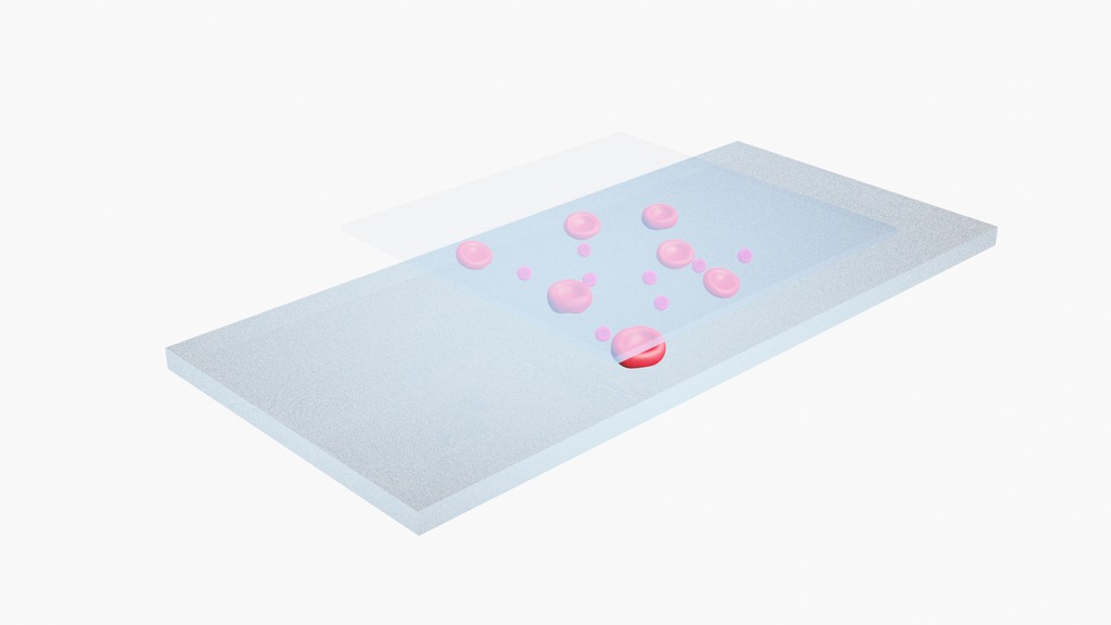
Fig 7. Glass measuring chamber for the optical tweezers measurements made with Eevee render in Blender
Fusion 360 is more about the exact parameters of engineered objects (parametric design), while Blender is more powerful for the artistic rendering and physics effects. My final project parts are non trivial, at least so far and most likely only for me, and I'm not sure yet about the materials, shapes and dimensions. Currently in our Lab we have this kind of stage from Thorlabs.
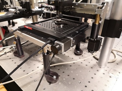
Fig 8. Commercial motorized XY stage
I have to come up with a design, which will let me to have a hole in the middle, where the sample glass chamber will be placed and highlighted underneath.
A standard microscope slide measures about 75 mm by 25 mm, I have started from it.
So I have started with a great tutorial from Lars Christensen aimed to help very beginners.
Shortcuts in Fusion 360:I have found commersially available metal stages and currently I'm checking the existing designs, thinking how to adapt them for my project.
I decided to sketch straight in Fusion 360 without preliminary sketching in Inkscape, as it seemed easier for me to draw with knowing the parameters and being able to see the result in 3D. So far I got very simple model of the stage top. I have recorded a video with Game bar - Windows 10 built-in free screen recorder, which can be started by hitting WINDOWS+G. Then using the simple menu I recorded my actions. After recording, video will be saved in the Captures folder, which by default is in your Videos folder. The cons of the software is that it can't record full screen, webcam, or specific a resolution to capture, from the other side it is very simple and free. To compress video I used online service Online convertor.
Some 3D models can be found online, and incorporated into the design. For example, most likely in my final project I'm going to use NEMA 17 stepper motor NEMA 17 stepper motor. From the same page of Sparkfun, I downloaded the 3D model. I made the motor mount for NEMA 17:
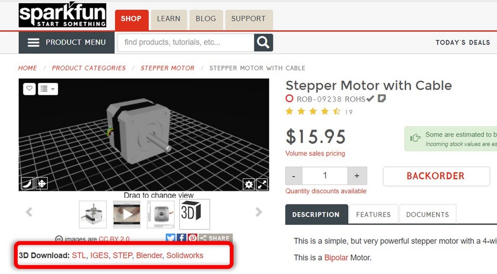
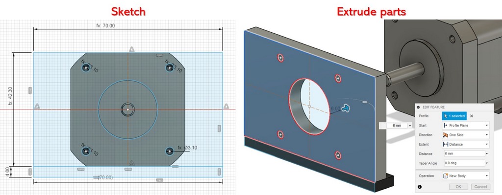
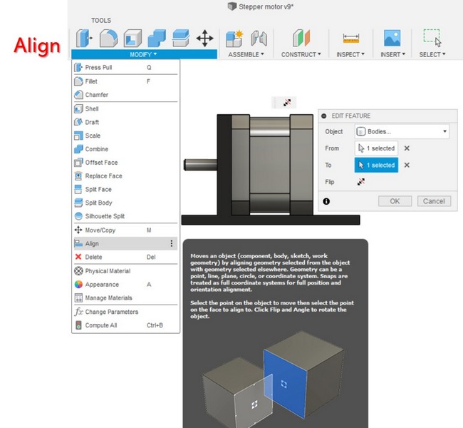
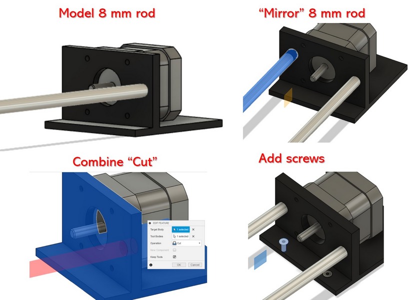
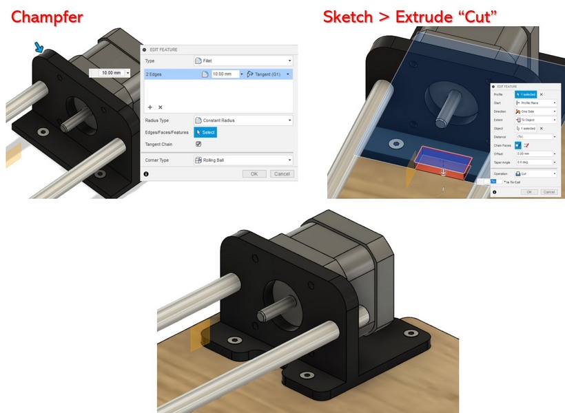
Fig 9. Designing the motor mount for the stepper motor in Fusion 360.
FILES:
