Project development
Final result
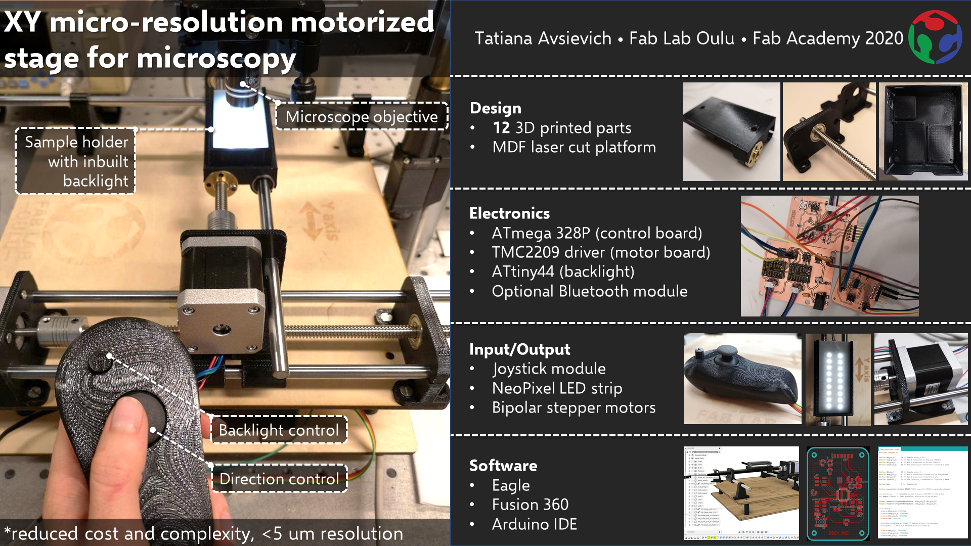
Final slide (1920x1080)
Project idea
Motorized translational microscopic stage
My optical tweezers setup requires the control of sample positioning, which is crucial for the measurements. Commercially available stages are very expensive, so I want to check, if I can create my own Microscope Automated XY Stage with a desirable properties.
- XY sample sliding directions
- LED backlight for the sample underneath the stage with remote control
- Remote motion control
- Adjustable legs height
- Microscope Automated XY Stage (more)
- 3d printed linear stage
- A 3D Printed Toolbox for Opto-Mechanical Components
- Similar projects on STLfinder
- Microscope Automated XY Stage
- Github open project on 3D printed translation equipment
- Stage with a built-in backlight
- Openstage: A Low-Cost Motorized Microscope Stage with Sub-Micron Positioning Accuracy. Approximate cost 350 EUR
- Project from fabacademy 2016
- X and Y stepper motors. EXAMPLE: Mercury Stepper Motor with Cable from Sparkfun, better performance, but considerably higher price Vexta PK243M
- Micrometer
- LED light
- PCBs
- Metal shafts
- 3D printed and/or laser cut parts
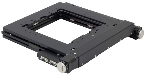
The example of commercially available stage
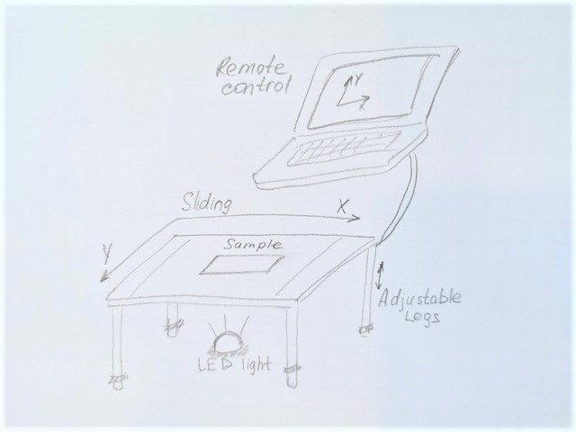
The sketch of motorized microscopy stage with adjustable legs, LED backlight and remote control of XY sliding
Componentes needed UPDATE:
- 2 stepper motors for X and Y directions: NEMA 17 (200 steps, 1.8)
- LED light
- PCB
- Guide rods
- 3D printed and/or laser cut parts
- Microcontroller (Arduino or ESP32) to control the X and Y motions
Motorized stage design
The key part of my final project is the stepper motor. After considering many options of different stepper motors I eventially chose the ROB-10846 from Sparkfun Electronics, due to the price/performance ratio (more about the motor on WEEK 9). This stepper motor has mainly the same dimensions as the popular NEMA 17 model, except the ROB-10846 is about 8 mm longer. Therefore, I downloaded 3D model of NEMA 17 (there are plenty of them for free) and just fixed the length.
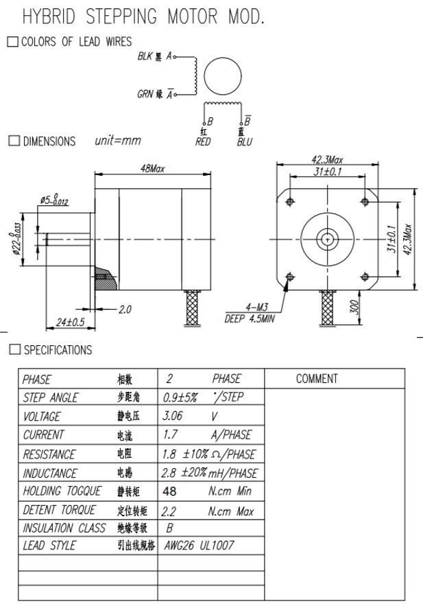
Fig 1. ROB-10846 specifications
Project design in Autodesk took some time, I stopped on a Version27. I started with a mount design on WEEK 2, and then almost finished the design I posted on WEEK 10.
Instead of drawing some technical parts I ease my life by downloading them from the internet. These are the parts I used from Traceparts Design Library and GRABCAD Library:
- Stepper motor NEMA 17
- Leadscrew with M8 with nut
- Liner Ball bearing LM8UU
- Leadscrew with M8 with nut
- Japanese Ball Bearing 809
- Flexible Coupler 5 to 8 mm
- Hexagon socket countersunk head cap screw M3
In the drawing I tried to make a full realistic model of the setup, which was crucial in for fabrication of the 3D printed parts, to ensure their proper alignment in the system.
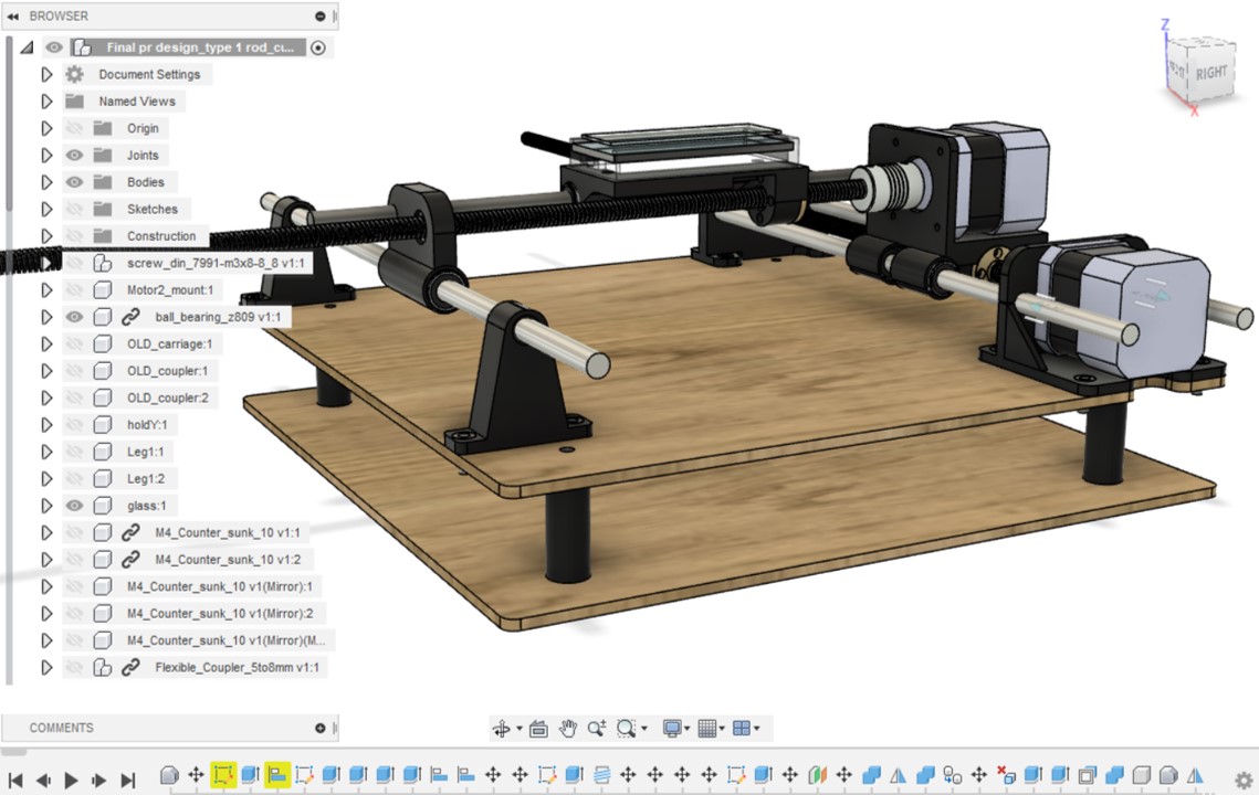
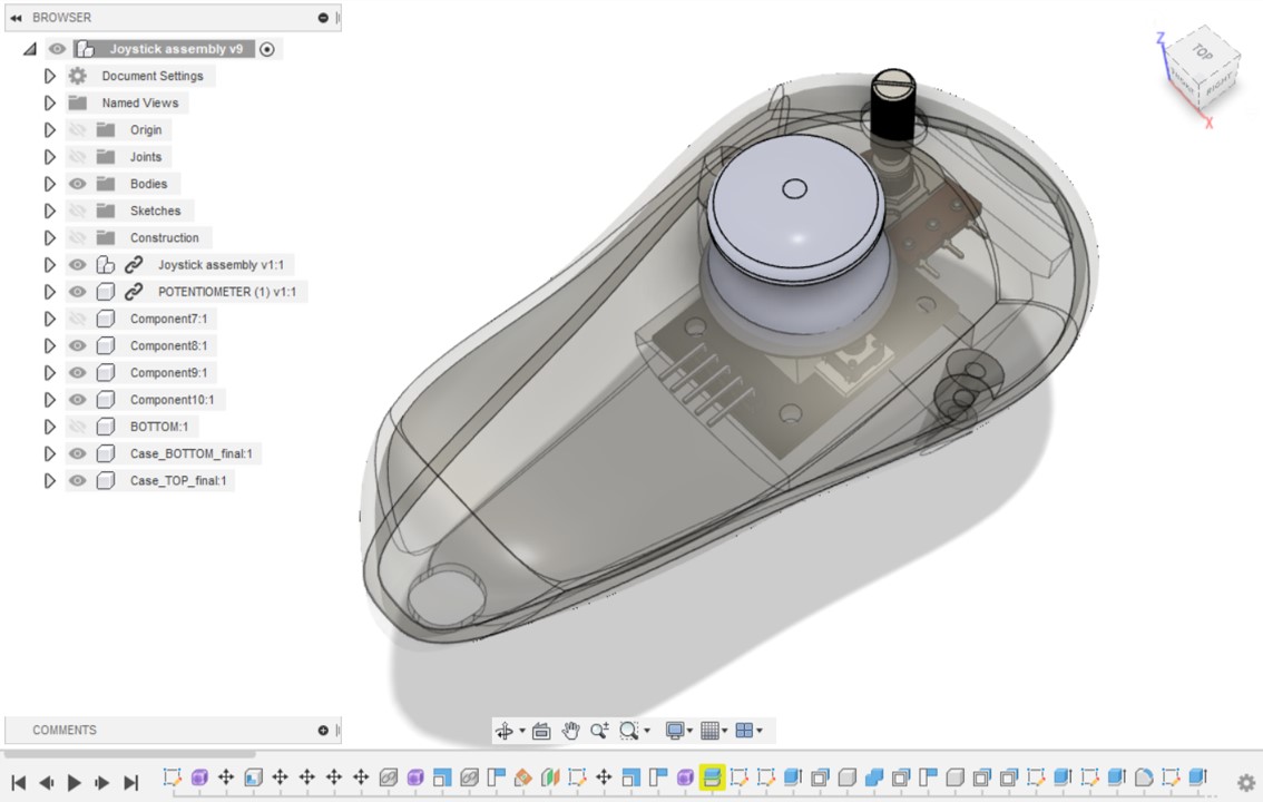
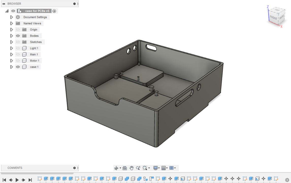
Fig 2. Autodesk Fusion 360 design of the final project: Stage assembly, Joystick and Case for electronics.
Fusion 360 design files:
Mechanical parts production
3D printing
To print the parts I used Stratasys Fortus 380mc 3D printer (how to use the machine on WEEK 5) . Approximate amount of the ABS material used is 150 cm3.
- 1. Motor X mount.STL
- 2. Motor X carriage.STL
- 3. Rod X bearing bracket.STL
- 4. Sample carriage Y.STL
- 5. Rod Y bearing sliding bracket.STL
- 6. Rod X brackets.STL
- 7. Backlight case.STL
- 8. Platform support.STL
- 9. Joystick case_top.STL
- 10. Joystick case_bottom.STL
- 11. Potentiometer button.STL
- 12. Case for electronics.STL
Laser cutting
To cut the parts with Epilog Fusion M2 40 Laser cutting machine (how to use laser cutter on WEEK 3) I used the following settings:
4 mm Plywood: Speed = 20%, Power = 100%, Frequency = 20%
3 mm Acrylic: Speed = 15%, Power = 100%, Frequency = 100%
- 13. Plywood “platform-case” for electronics_CUT+ENGRAVE.PDF
- 13. Platform bottom.PDF
- 14. Acrylic cover (sand blasted).PDF
- SVG files for laser cut parts
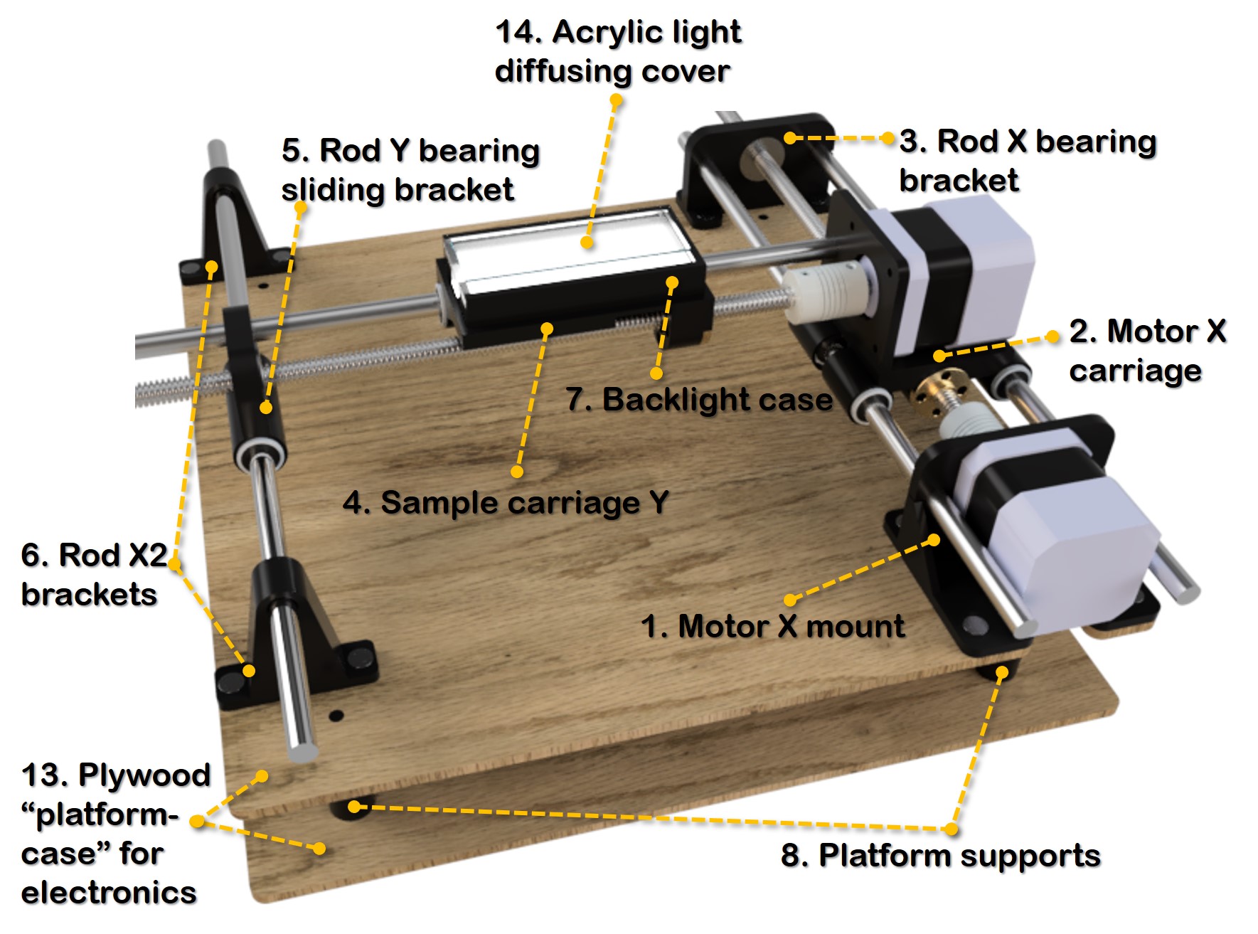
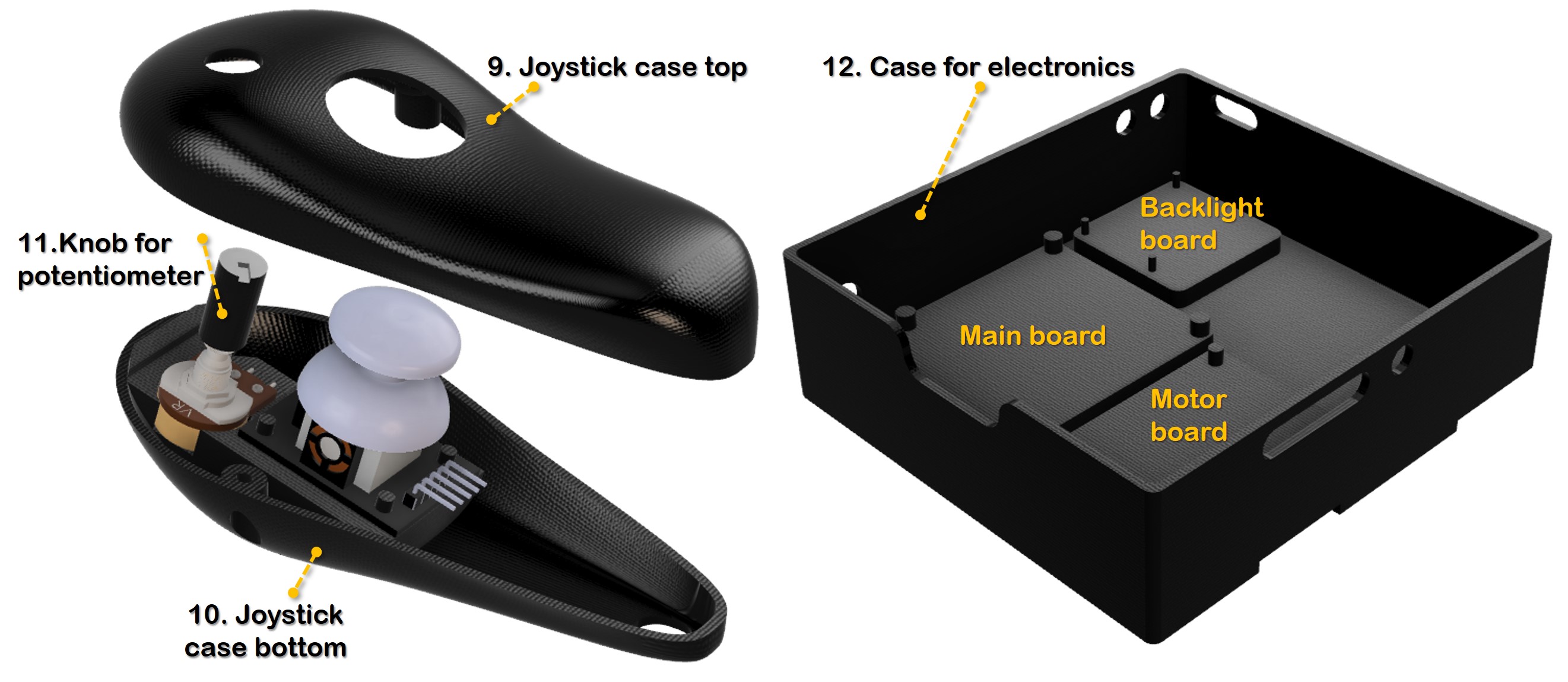
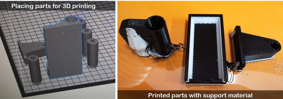
Fig 3. STL files were imported into GrabCAD Print software, I used Infill density 18%.
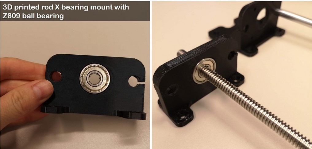
Fig 4. Parts came out very firm, providing good fit of the ball bearings and metal rods.
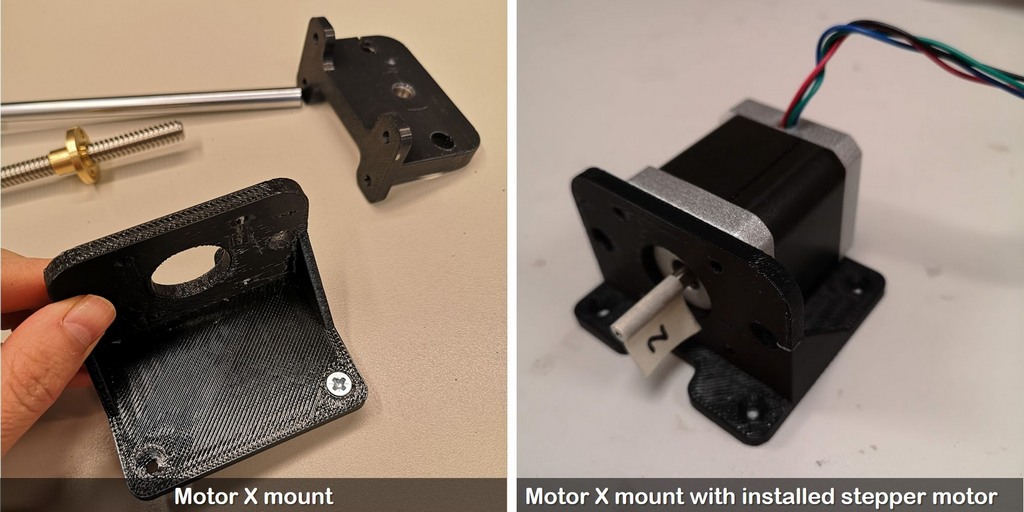
Fig 5. M3 screw in the motor X mount to attach to the platform
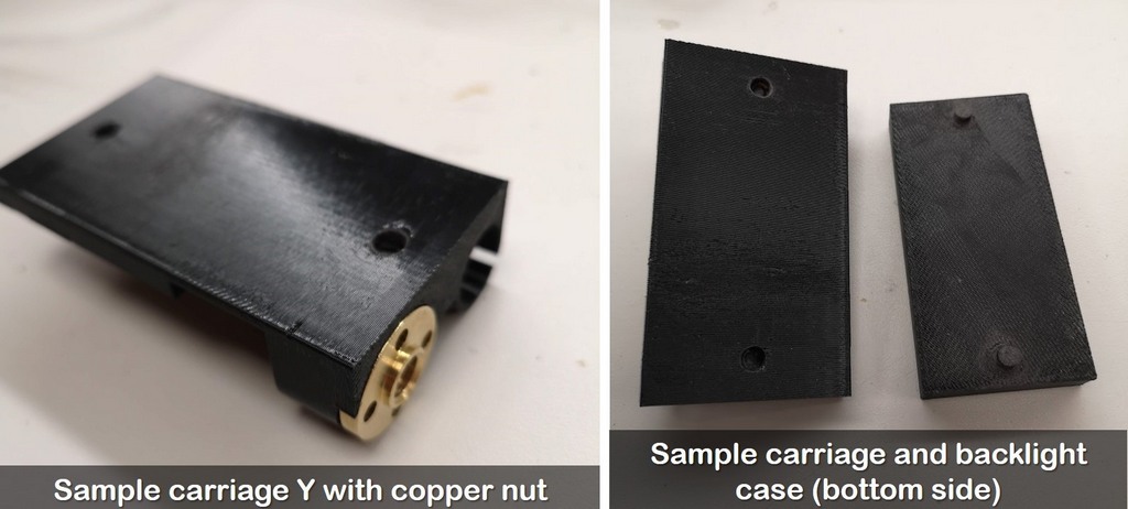
Fig 6. Backlight case will be firmly attached to the sample carrige with 2 pins
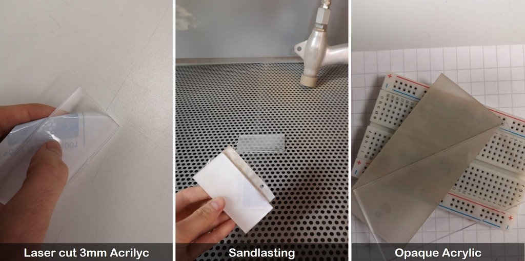
Fig 7. Sandblasting the acrilyc cover to make diffusive cover
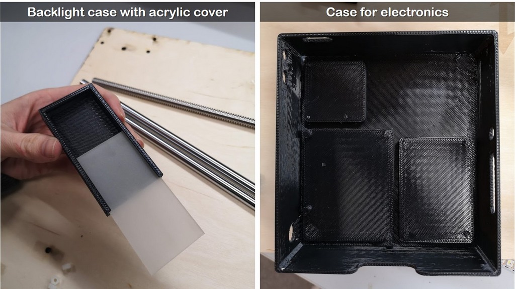
Fig 8. Sandblasted acrylic cover sliding into the slots of the backlight case
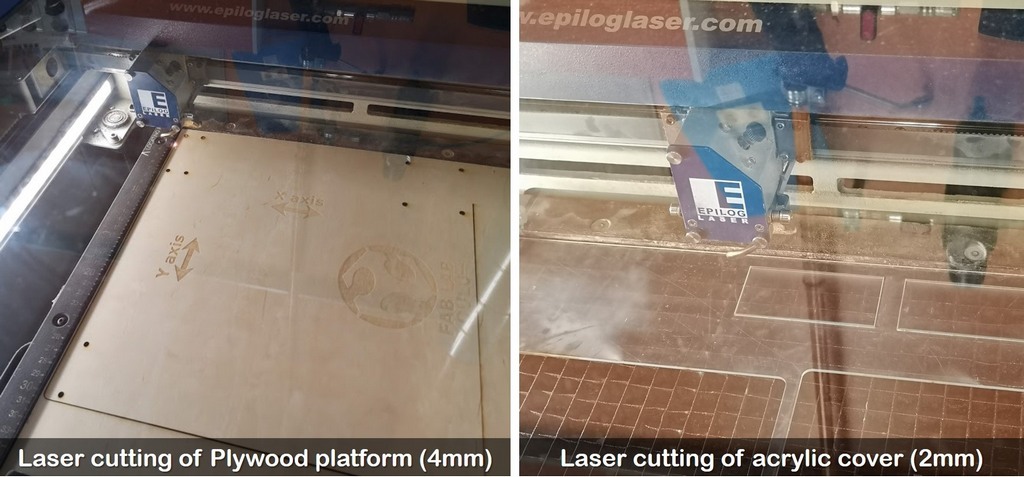
Fig 9. Cutting the platfrom from 4mm Plywood and cover of the backlight case with Epilog Fusion M2 40 Laser cutting machine
A linear actuator produces a linear translation. Inside the rotor there is a threaded precision nut with a lead screw. The lead screw in turn is fixed to the translation stage with a nut. As the rotor turns linear motion is achieved directly through the nut and threaded screw. The size of the leadscrew depends on the range of translation required. The precision of the motion depends on the step size of the stepper motor and on the coupling between the motor and lead screw. The threads of the lead screw allow a small rotational force to translate into a large load capability. A small lead (more threads per inch) will provide a high force and resolution output. A large lead (fewer threads) will provide a lower force, but correspondingly higher linear speed.
Hardware
Positioning system: stepper motor ROB-10846
There are 2 main modules for the final project: one is to control 2 stepper motors, and another one to control the backlight.
To achieve the minimal steps (microsteps) of the stepper motor, I decided to use 400 steps/revolution stepper motor ROB-10846 from SparkFun with TMC2209 silentstepstick driver. The first steps towards the application of the stepper motor in final project are on the page Input devices (WEEK 9).
I was considering several stepper motors to be used, which were apllied in similar projects, and appeared to be polupar models for 3D printing.
| Motor | 28BYJ-48 | NEMA17 | Vexta PK243M | Mercury | ROB-10846 |
|---|---|---|---|---|---|
| Steps per revolution /half-steps |
2048/ 4096 |
400 | 200 or 400 | 200 | 400 |
| Step angle | Half step 0.0879° Full step 0.176° |
0.9° | 0.9° | 1.8° | 0.9° |
| Coil Type | Unipolar | Bipolar | Unipolar/Bipolar | Bipolar | Bipolar |
| Phase | 4 | 2 | 2 | 2 | 2 |
| Rated voltage, V | 5 | 3 | 4/5.6 | 12 | 3 |
| Price, EUR | 7 | 16.57 | 56.3 | 14.72 | 16.54 |
My purpose is to run the motor smooth and slow as possible. At the start I was sure that smallest motor can't be applied for my purpose. However, because of the gearing inside, 28BYJ-48 provides the highest amount of the steps per revolution. After controlling the motor with Arduino during WEEK 9, I saw, that the speed is easy to control, but what matters is the step size, once I tried to make it very slow, steps are very discrete. Below are some projects, where high resolution of the sample positioning was achieved.
28BYJ-48 possibilities:
- ESP32 Micro Robot Arm with A4988 driver with SMOOTH movements.
- Stage with nano-resolution (Arduino)
Mechaduiono
Slow and smooth motion with Mechaduiono.
NEMA 17 (200 steps/rev)
DRV8825 driver for instance allows to use between 1/2 to 1/32 micro-steps, so the 200 full steps can become up to 6400 micro-steps for making one full rotation thus providing much greater precision if it is needed. One more option to achieve smothness of movements is TL Smoother (TL Smoother Test: A4988 and DRV8825). Microstepping should be applied carefully, as the torque drastically deacrease with a step number increase, explanations are given here.
Stepper motor driver TMC2209 silentsick
The driver's characteristics and first testing can be found on the Input devices (WEEK 9) page. For the final project, I will have to perform the so-called "microstepping". Microstepping control divides each full step into smaller steps to help smooth out the motor’s rotation, especially at slow speeds. The concept of micro-stepping is to make the lower speeds a smoother motion instead of the cogging you would get with a stepper. This is done by controlling the ratio of the current applied to both coils to attract the motor shaft to a position between the coils but closer to one coil than the other. By appropriately managing the current in the coils it is possible to make the motor move in smaller steps.
I got the TMC2209 silentsick from Digikey, which has the best characteristics to make motor rotation smooth, silent and achive the small steps up to 1/256 resolution.
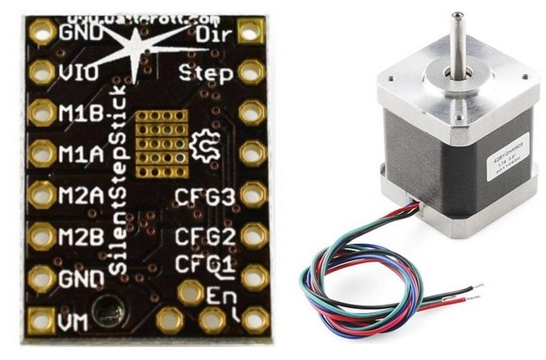
Fig 10. TMC2209 silentsick carrier and ROB-10846 stepper motor.
When I received my Digikey parcel with stepper motors and drivers, at first, I checked the motor drivers with Arduino MEGA2560, cause it has more pins, allowing the UART communication with the stepper drivers. Later on I decided to simplify the code and ignore the UART for the first project implementation, and switched to Arduino Uno board. TMC drivers motors specifications are very advanced, promising smooth motion and high step resolution. One of the distinct features of these drivers is UART communication. The microstepping up to 1/256 resolution can be achieved, but for my purpose it is probably an overkill, so I used microstepping 1/64, which together with threaded rod, resulted in 25600 steps per revolution.
Testing slow rotation of the motors with TMC2209 ran by Arduino UNO. This is not the "slow motion" effect on a video, but the real performance of the driver at 1/64 microstepping.
XY Dual Axis Joystick Module
I got the Joystick module from the Arduino UNO kit. Joystick module has the power pins 3.3-5V and GND, 2 analogue outputs VRx and VRy (Variable Resistance), and the push button SW (switch) digital pin that activates when you push the joystick down. In principal joystick has two potentiometers one for vertical movement and one for horizontal movement. When 5V is applied at one end of the potentiometer and 0V at the other end of the potentiometer, and the wiper adopts a value in between these voltages, while analogue values can be read.
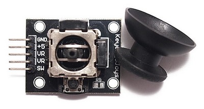
Fig 11. XY dual axis joystick module
NeoPixels for Backlight
I found two ways to make the backlight, the one is to use the number of connected LEDs, and the another one was to buy a ready backlight module from Adafruit. However, having the NeoPixel strip, the backlight is easy to fabricate: it can be done with any desirable dimensions and easy to control more about testing Neopixels on WEEK 11. The strip has only 3 contacts: 5V, data, and GND, and requires 5V DC power supply. I will use a potentiometer to control the brightness of NeoPixels.
Electronics design and production
One of the most challenging part for me was electronics design, with COVID restrictions and shortage of time, I was lucky to have my friend Gleb helping me, also I found useful information from previous years student's pages. Because of his help, boards were prepared in 3 very exhausting days. A huge thanks to Mikko, who was always there to assisst with a plenty of questions. And thanks to polar days, even working till late night we still were able to catch the sunlight!
I have simplified the whole idea of the project - according to the suggestion of our instructor Ivan Milara instead of placing everything on one board, I decided to make 3 boards, so if something goes wrong, it is easier to allocate the malfunction.
- Main control board (microcontroller ATmega328P)
- Motor drivers board (2 Silentstick TMC2209)
- Backlight board (ATtiny44) controlling NeoPixels
To design the schematic and layout of the boards I used Autodesk Eagle and followed the same steps for the PCB production as described on the page WEEK 4 Electronics production. The COMPONENTS for each board and part are listed in the section List of components.
Motor board Silentstick TMC2209
The 12V power supply is on the motor board because it provides the power for the motors pin Vm on the driver, and then going through a Voltage regulator will provide 5V line to power up other parts of the system.
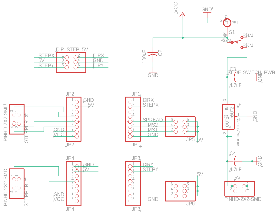
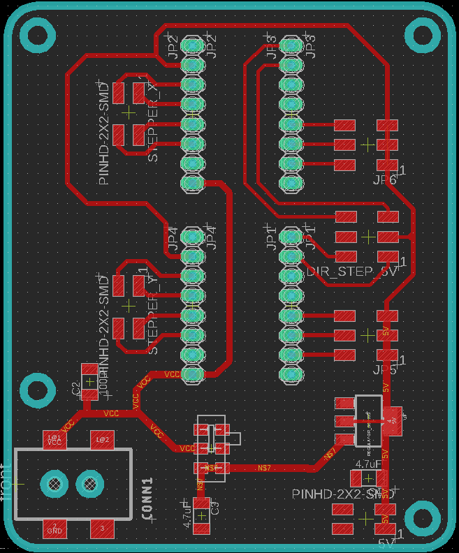
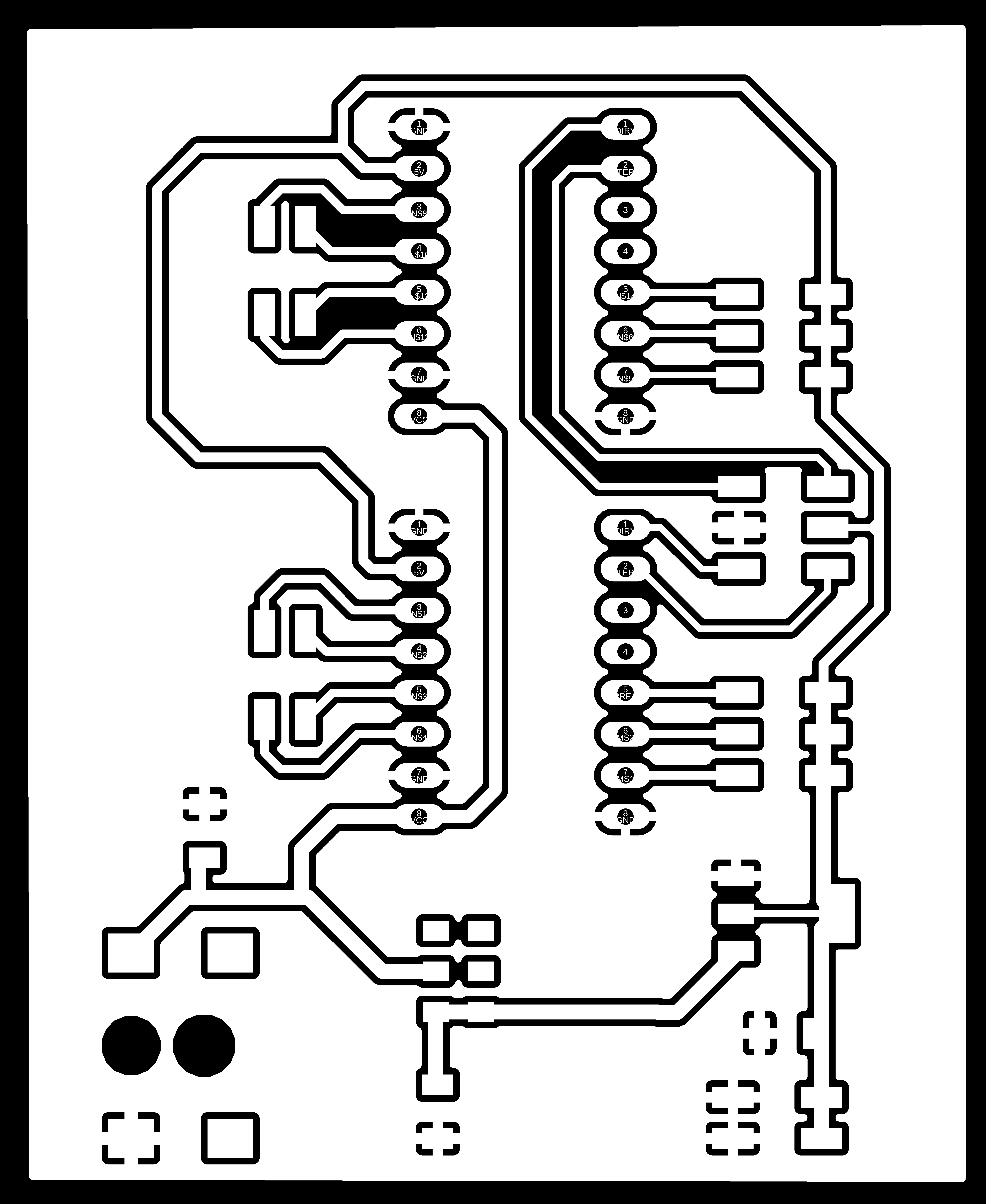
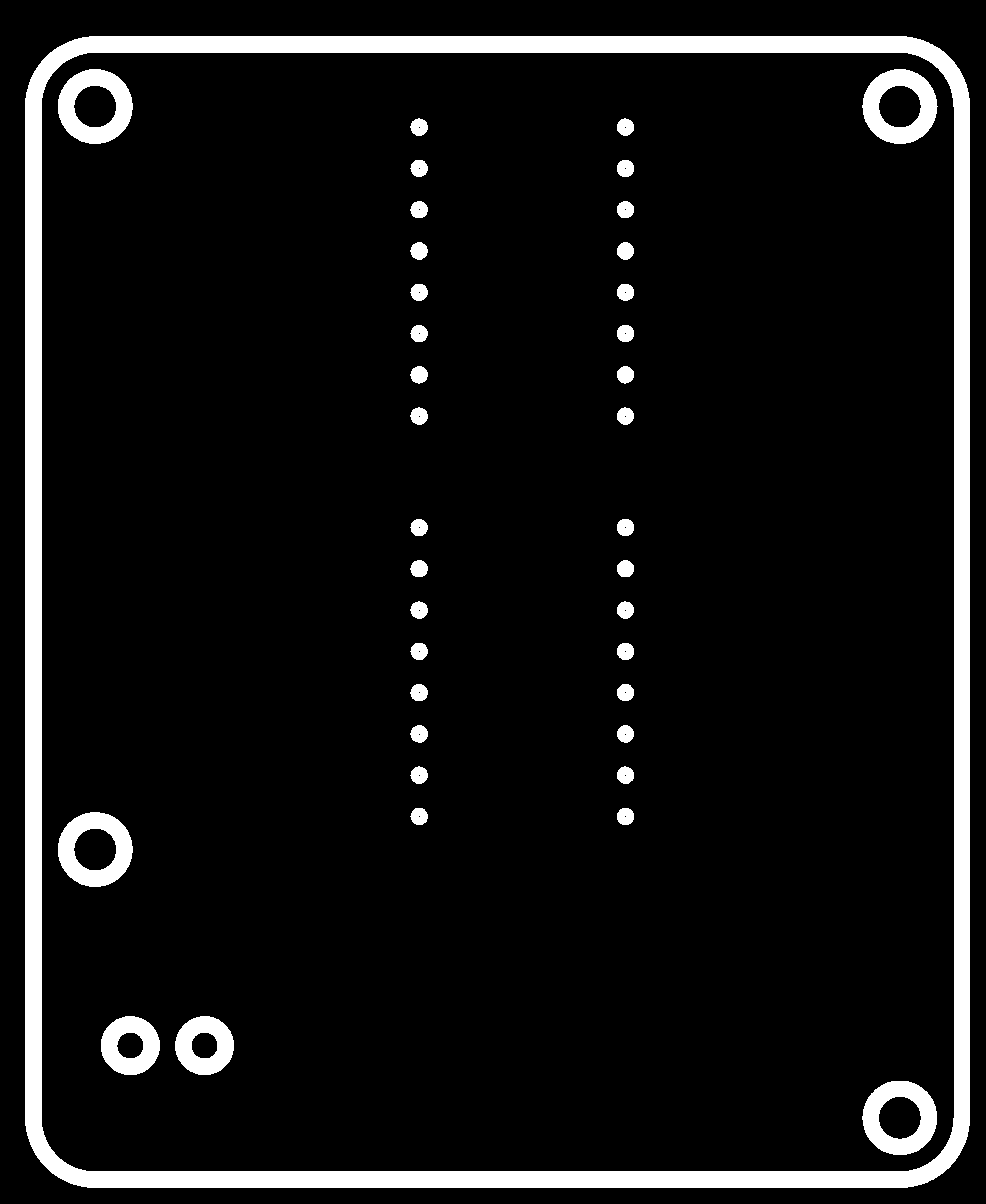
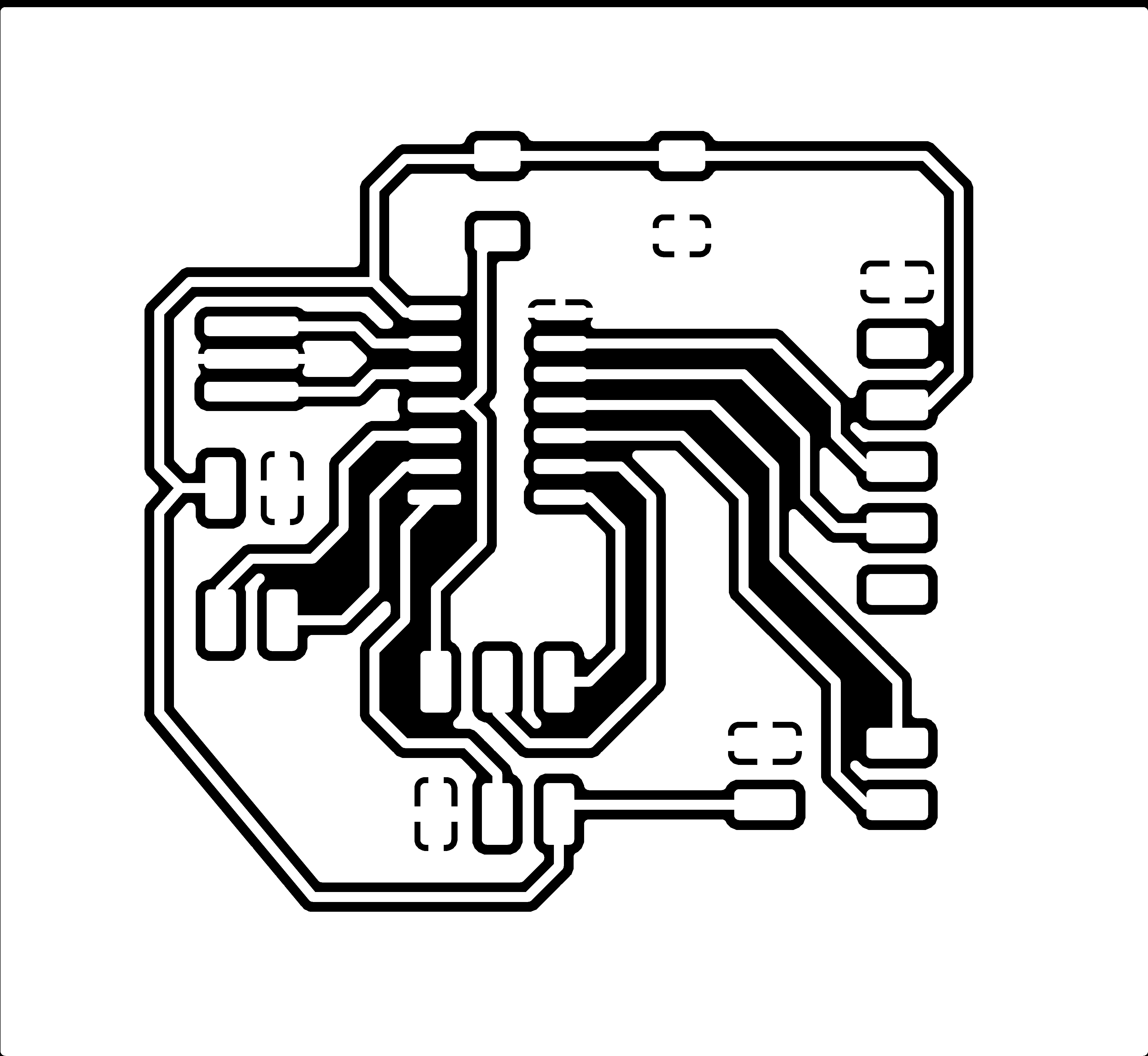
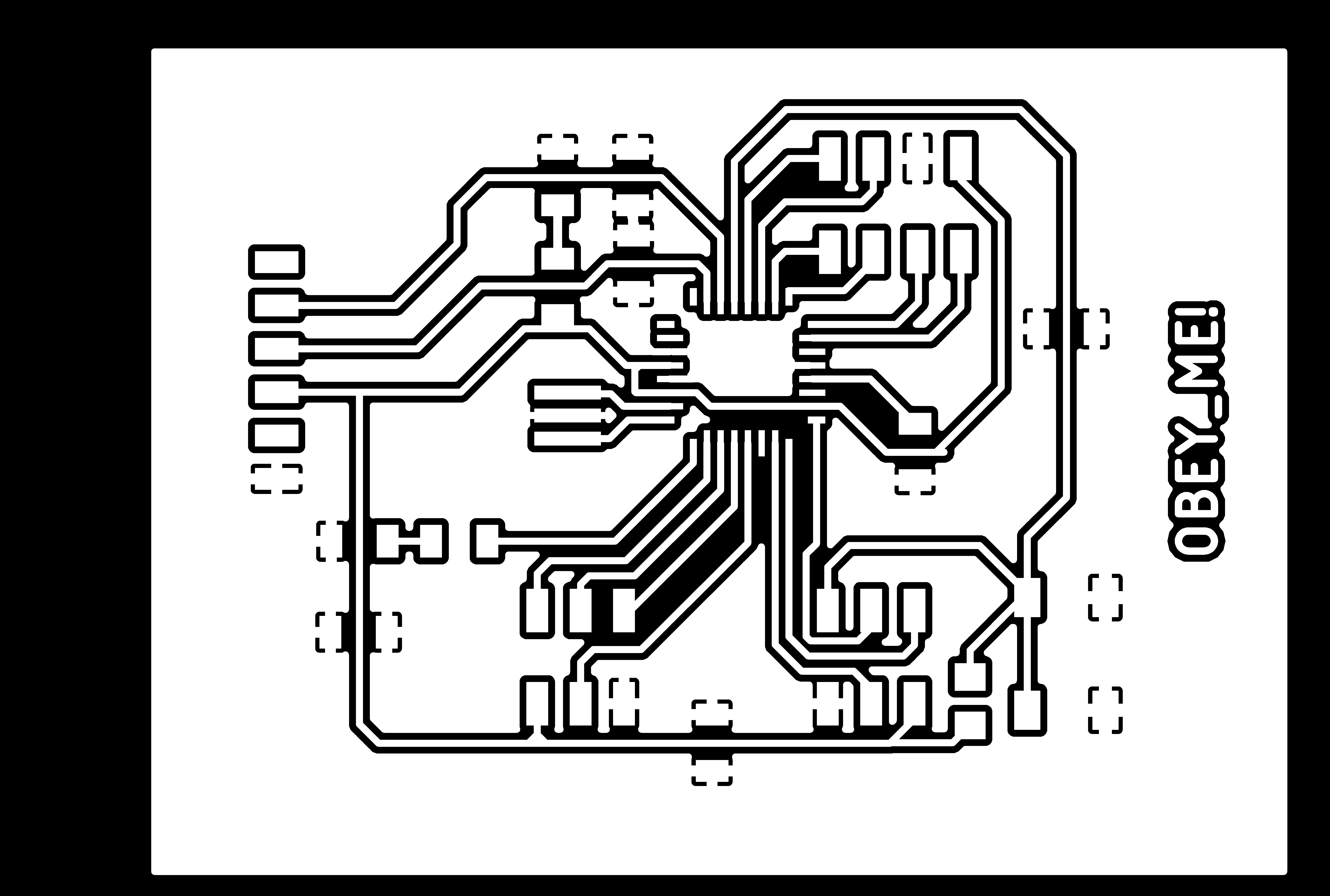
Fig 12. Schematic and Layout of the Motor's Driver Board in Eagle
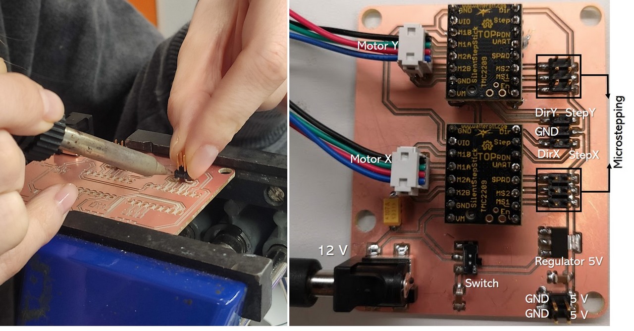
Fig 13. Soldered Motor's Driver Board

Fig 14. 2-pin headers for microstepping control. In the current configuration 1/64 microstepping
Motors are controlled via Dir and Step pins, which will be connected to the main ATmega328P microcontroller. 2x2 pin header on the right bottom corner is providing 5V power and GND for 2 other boards.
MOTOR PCB FILES:
Backlight board ATtiny44
The steps of backlight board production are posted on the page Output devices WEEK 11. The programming of ATtiny44 was used to control the NeoPixel LEDs.
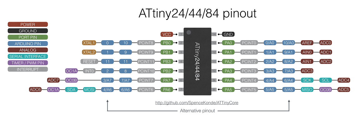
Fig 15. ATtiny44 pinout
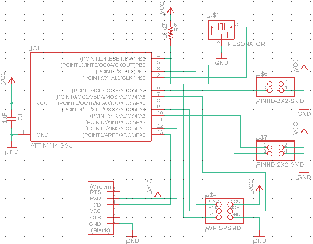
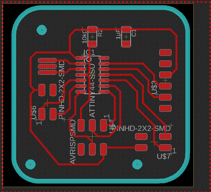
Fig 16. Schematic and Layout of the Backlight Board in Eagle
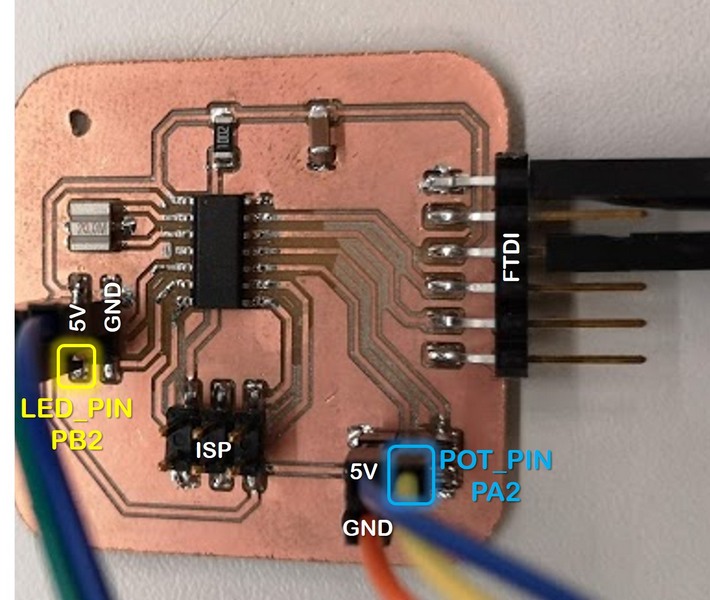
Fig 17. Schematic and Layout of the Backlight Board in Eagle
BACKLIGHT PCB FILES:Main board ATmega328P
At first, I checked the total number and functionality of the pins required to control the stage. Since the test was successful with Arduino Uno, it was easier to switch to the ATmega328P microcontroller. Besides, I found the pages of Yasir Shafiullah and Ari Vuokila, who used the same microcontroller to control stepper motors.
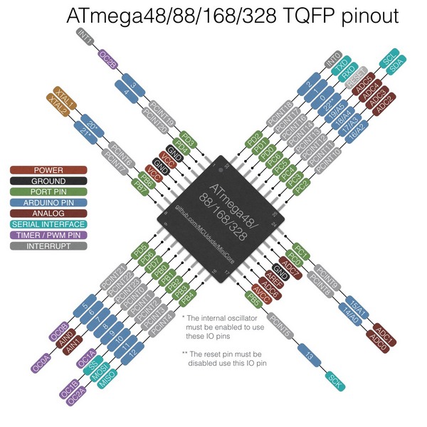
Fig 18. Switching from Arduino Uno to ATmega 328P pinout with corresponding Arduino Uno pins
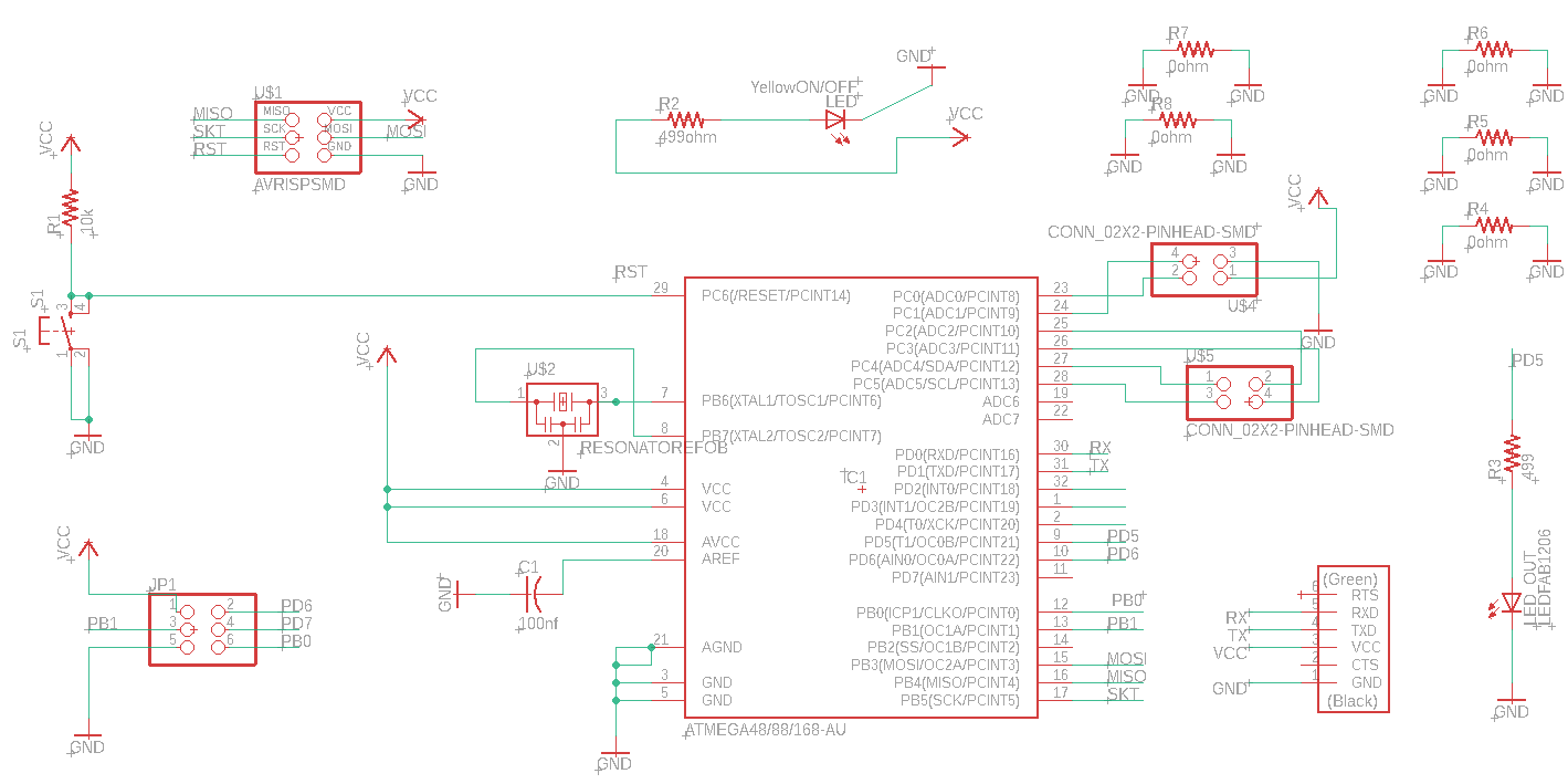
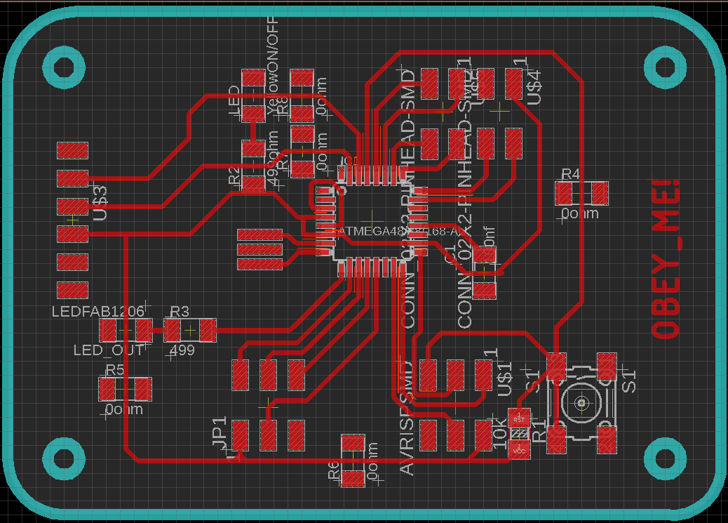
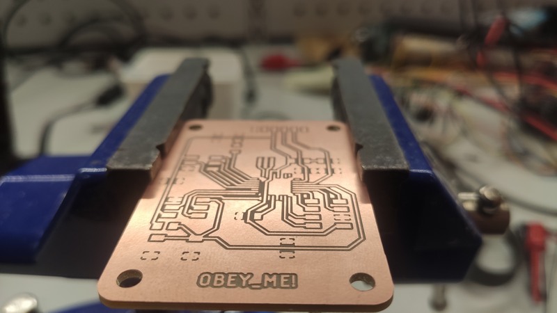
Fig 19. Schematic and Layout of the Main Board in Eagle, and milled PCB
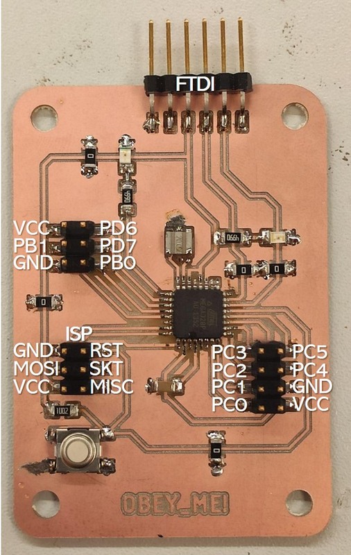
Fig 20. Soldered Main Board
MAIN PCB FILES:
Programming
I programmed 2 microcontrolles ATtiny44 of the Backlight and ATmega328P of the main board. Both boards have ISP and FTDI headers for programming with USBtinyISP programmer. Programming basically requires following:
- Connection: ISP cable is connecting the ISP headers of the programmer and backlight board: MISO, MOSI, SCK, RESET, VCC, and GND of the programmer to the corresponding pins on the ATtiny. Both FTDI cabels from the backlight PCB and programmer are connected to USB port. FTDI here is powering the programmer.
- Installing the Device Manager for boards in Ardduino IDE, “Additional Boards Manager URLs”:
Attiny44:https://raw.githubusercontent.com/damellis/attiny/ide-1.6.x-boards-manager/package_damellis_attiny_index.json
Atmega328P:https://raw.githubusercontent.com/carlosefr/atmega/master/package_carlosefr_atmega_index.json
I changed the code for ATtiny44 from WEEK 11 for 18 NeoPixels. Potentiometer is connected to the analog pin PA2 of Attiny44 (Arduino pin 2).
Fig 21. Arduino sketch for programming ATtiny44 to control NeoPixels of the Backlight module
I found 2 example codes: one is for DRV8825 stepper motor to fit my system from this page, and another one for TMC driver by Teemu Mäntykallio. So I modified and merged some parts, simplifying it, plus added the code for Joystick input from the code I used on a WEEK 9. My code is very simple, it includes 2 motors for X and Y axis of the stage. The number of steps is defined in the code stepsPerRevolution is 256000 = 400 steps per/rev of the motor x 64 microstepping.
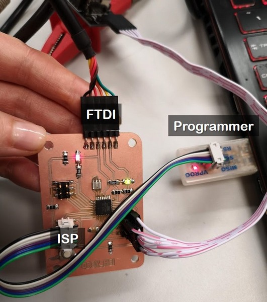
Fig 22. Programming the main board ATmega328P microcontroller with USBtinyISP programmer (same as for ATtiny44)
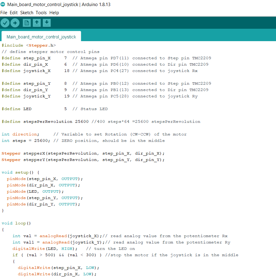
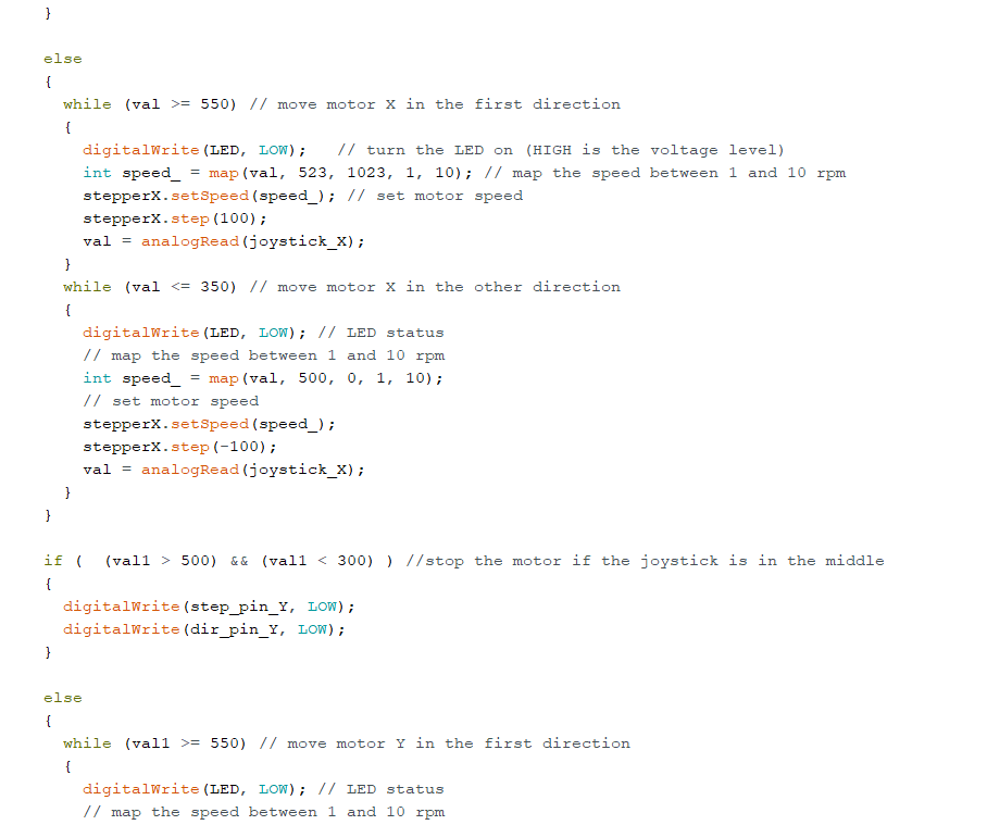
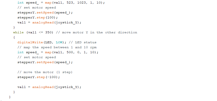
Fig 23. Arduino sketch for programming ATmega328P
System integration and packaging
Mechanics
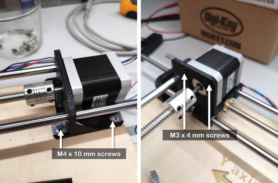
Fig 24. Mounting the motors to 3D printed carriages
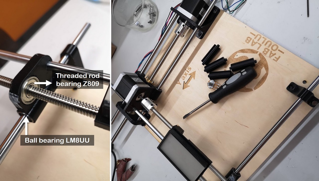
Fig 25. Rod Y bearing sliding bracket installation and final mechanical assembly
Backlight
Backlight consistes of 2 connected 8 LEDs NeoPixels strips, placed into 3D printed case and covered with diffusive acrilyc cover.
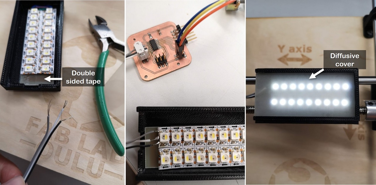
Fig 26. 2 connected NeoPixels strips attached with doudle sided tape into the case. Acrylic diffusive cover sliding into the slots of the case. Backlight module is attached to the Sample carriage Y with 2 pins
Joystick
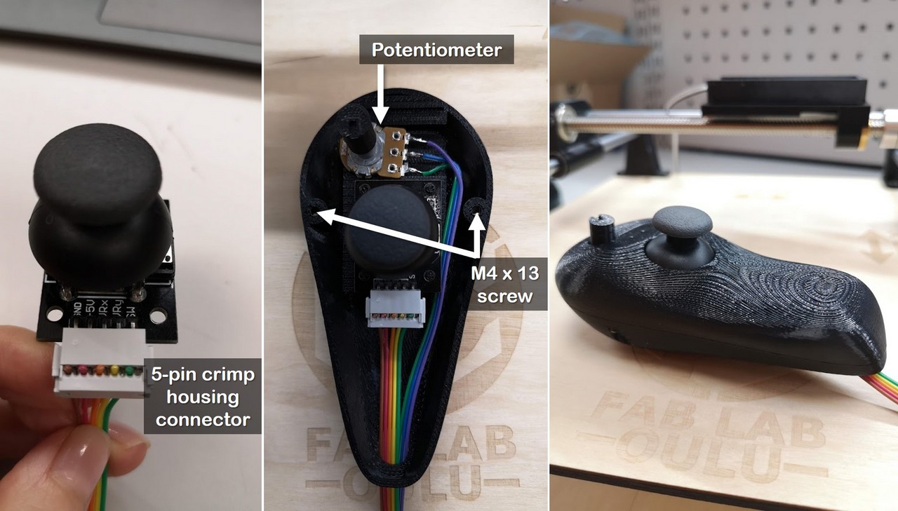
Fig 27. Control Joystick assembling
Electronics packaging
I made the case for the boards, however it wasn't the best design - I made the pins for each board, some of them got broken, it would be easier and better just to make a few wide pins for each PCB, and then attach them with screws.
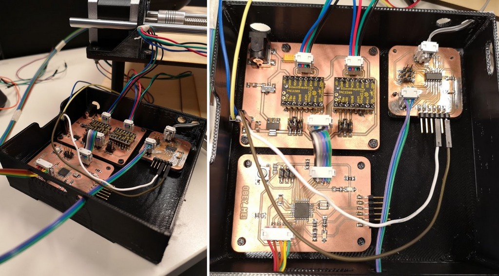
Fig 28. PCBs packed in the case for electronics
Final assembly
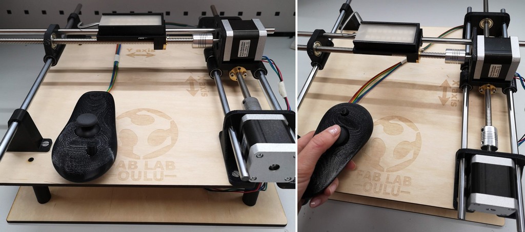
Fig 29. Final assembly of the stage
Some of the first tests: 1 Neopixel strip in the backlight case, high speed of rotation (rotation per minute (rpm) in the code is set to 100)
Evaluation
System estimation
The precision of the motion depends on the step size of the stepper motor and on the coupling between the motor and lead screw. The threads of the lead screw allow a small rotational force to translate into a large load capability depending on the steepness of the ramp, which is a function of the lead, pitch, and diameter of the screw. A small lead (more threads per inch) will provide a high force and resolution output. A large lead (fewer threads) will provide a lower force, but correspondingly higher linear speed.
The simplest way is to check the travel of the lead screw nut: Turn the nut one full revolution. The distance nut traveled in millimeters in one full revolution is Lead. The distance between the threads is Pitch. For the leadscrew with nut I'm using the lead and pitch are both 2 mm.
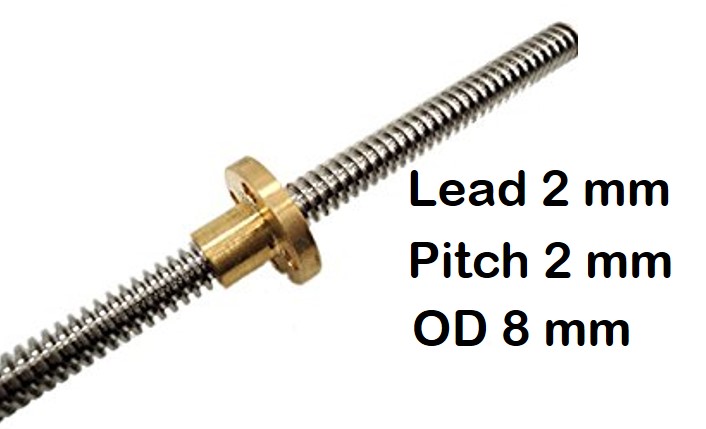
Fig 30. Leadscrew with brass nut
Resolution (μm)=Pitchspindle/No. of motor steps,where Pitch spindle is the incline of the spindle per revolution (1 mm = 1000 μm) and No. of steps is the total number of steps per revolution of the stepper motor, therefore:
Resolution (μm) = 2000μm/400 = 5 μmTo calculate how how many steps per millimeter in my system, I found the online calculator. I put the data for my system, the only difference is microstepping 1/64 instead of maximum available 1/32. Therefore, eventually I get 6400x2=12800 steps per 1 mm! This provides a reeeeeeeeeeeeeeeeeeeeeaaaaaalllllllllyyyyyyyyyyy slow and smooth motion of the sample, exactly what I need.
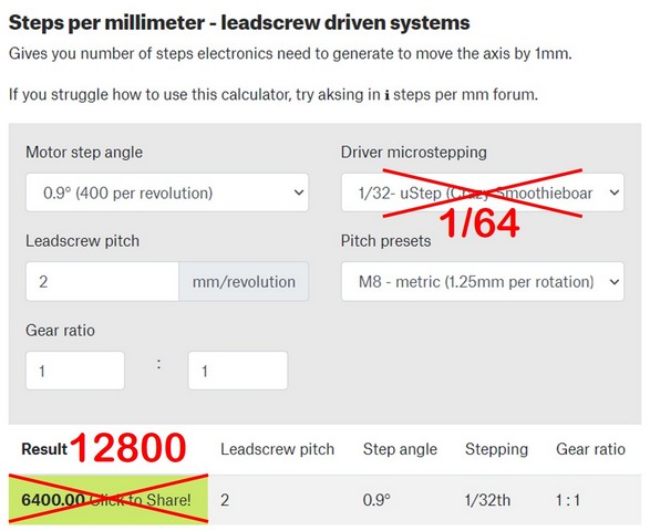
Fig 31. Calculation of number of steps electronics need to generate to move the axis by 1 mm. Calculator Steps per millimeter - leadscrew driven systems
The wheight of the sample is very low, therefore it shouldn't affect the components of the stage and hence the performance.
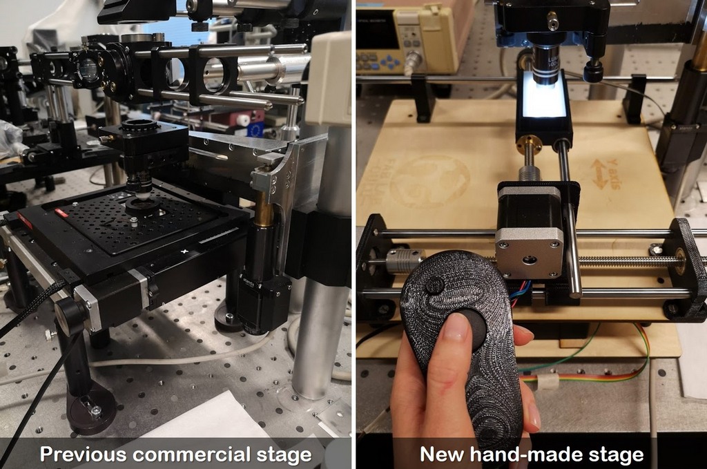
Fig 32. Switching from commercial system to hand-made stage
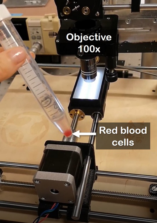
Fig 33. Red blood cells are observed under 100x magnification
Changing the backlight brightness and moving the stage
List of components
My first estimation is posted on the page Applications and implications
| Component | Properties/Function | Qty | Buy/Produce | Price, EUR |
|---|---|---|---|---|
| ROB-10846 Stepper motor | 3A, 400 steps | 2 | Digikey | 33.08 |
| Analogue Joystick module, 5-pin | Motor's direction control | 1 | Aliexpress | ≈1 |
| Rotary potentiometer | Backlight NeoPixel brightness control | 2 | Aliexpress | ≈10 |
| 5-pin crimp housing connector | Connecting wires of Joystick module | 1 | Available at local Fablab | ≈0.2 |
| 2x2 pin crimp housing connector | Connecting wires motors | 4 | Available at local Fablab | ≈0.8 |
| 2x3 pin crimp housing connector | Connecting pins of the motor drivers to the main board | 2 | Available at local Fablab | ≈0.4 |
| Lead Screw 8mm Thread With Copper Nut | Pitch 2mm, length 300mm | 2 | Available at local Fablab | ≈10 |
| Flexible 8mm - 5mm coupler | Coupler between the motor shaft and threaded rod | 2 | Available at local Fablab | ≈2 |
| Stainless rods | 4 | 4 | Available at local Fablab | ≈6 |
| 3D printed parts | 5 Mounts, Backlight case, Joystick case, 4 platform support legs | ≈45 | ||
| Laser cut parts | Acrylic cover for backlight, 1 4mm Plywood platforms | 3 | ||
| Ball bearing LM8UU | Holding the moving stages on the metal rods | 6 | Available at local Fablab | ≈2 |
| Bearing Z809 | Threaded rod bearing | 2 | Available at local Fablab | ≈2 |
| M4 screws | Attach mounts to the platform and 2 parts of Joystick | 14 | Fab Inventory | 0.84 |
| M3 screws | Attach motors to the mounts | 8 | Fab Inventory | 0.84 |
MAIN BOARD |
||||
| ATmega328P | Microcontroller | 1 | Available at local Fablab | ≈2 |
| Resistor 0Ω (RES 0.0 OHM 1-4W 5% 1206 SMD) | Wire link to connect traces | 5 | Fab Inventory | 0.05 |
| Resistor 499Ω (RES 499 OHM 1-4W 1% 1206 SMD) | Limit the current through the LED | 2 | Fab Inventory | 0.02 |
| Resistor 10 kΩ | Pull-up resistor | 1 | Fab Inventory | 0.01 |
| Capacitor 100nF | 1 | Available at local Fablab | 0.08 | |
| LED | LED GREEN CLEAR 1206 SMD | 2 | Fab Inventory | 0.3 |
| FTDI SMD header | Serial communication | 1 | Fab Inventory | 0.76 |
| Button Switch SWITCH TACT SMD W-GND 160GF | Reset for microcontroller | 1 | Fab Inventory | 0.84 |
| 20 MHz resonator | CER RESONATOR 20.00MHZ SMD | 1 | Fab Inventory | 0.43 |
| Male header 2x3 SMD | 6 Pos Header Connector 0.100"Surface Mount | 2 | Fab Inventory | 1.2 |
| Male header 2x4 SMD | 2 | Fab Inventory | 1.34 | |
| Single side circuit board stock | PCB-substrate | 1 | Fab Inventory | 1.40 |
MOTOR'S BOARD |
||||
| TMC2209 SILENTSTEPSTICK | STEPPER MOTOR DRIVER (Smooth microstepping up to 1/256 step!!!) | 2 | Digikey | 27.10 |
| Voltage regulator | IC REG LDO 5V 1A SOT223-3 | 1 | Fab Inventory | 0.45 |
| Power jack 2.1mm | Powering the setup (12V) | 1 | Fab Inventory | 1.47 |
| SWITCH SLIDE SPDT 12V 100MA GW | Power control | 1 | Fab Inventory | 0.84 |
| Male header 2x3 SMD | 6 Pos Header Connector 0.100"Surface Mount | 3 | Fab Inventory | 1.8 |
| Male header 2x4 SMD | 2 | Fab Inventory | 0.67 | |
| Capacitor 100nF | 1 | Available at local Fablab | 0.08 | |
| Capacitor 4.7uF | 2 | Fab Inventory | 0.08 | |
| 2 pin header jumpers | Microstepping setting | 2 | Available at local Fablab | 0.5 |
BACKLIGHT BOARD |
||||
| ATtiny44 | Fab Inventory | 1.18 | ||
| NEOPIXEL 8 | Backlight | 1 | Digikey | 2.30 |
| Power supply | 12V | 1 | Available at local Fablab | |
| Male header 2x2 SMD | 4 Pos Header Connector 0.100"Surface Mount | 2 | Fab Inventory | 1.32 |
| Male header 2x3 SMD | 6 Pos Header Connector 0.100"Surface Mount | 1 | Fab Inventory | 0.6 |
| 20 MHz resonator | CER RESONATOR 20.00MHZ SMD | 1 | Fab Inventory | 0.43 |
| Resistor 10 kΩ | Pull-up resistor | 1 | Fab Inventory | 0.01 |
| Capacitor 1uF | 2 | Fab Inventory | 0.07 | |
| FTDI SMD header | Serial communication | 1 | Fab Inventory | 0.76 |
| TOTAL COST | ≈162 |
I'm happy with a total cost of the project, yet I haven't used all the functionality of the stepper driver, which can be improved by using all the functionality of the TMC2209 stepper driver, and I didn't use more expensive analogues of motors. Commercial positioning systems come with software, made out of robust metal materials, and most important, they provide the reliable repeatability, but cost in a range of thousands of euros (≈ 5000). My system can't compete with some characteristics of commercial stages, but it fullfills the basic requirements for the precised sample positioning with high micrometer-scale resolution, and cost 30 times cheaper. Stage can be made by anyone with very basic knowledge in electronics (especially using the instructions above).
License
I intended to make my project available to anyone, theresore:
ShareAlike (sa) You let others copy, distribute, display, perform, and modify your work, as long as they distribute any modified work on the same terms. If they want to distribute modified works under other terms, they must get your permission first.
NonCommercial (nc) You let others copy, distribute, display, perform, and (unless you have chosen NoDerivatives) modify and use your work for any purpose other than commercially unless they get your permission first
