Networking
and Communications- individual assignment: design, build, and connect wired or wireless node(s) with network or bus addresses
- group assignment: send a message between two projects
#ArduinoUno#Atmega328P
#ArduinoUno#Atmega328P
I was in the group with Zhengya Gong, Yazan Barhoush, Noora Nyberg and Xinhui Hu. We were sending messages between 3 ATtiny412 boards connected with Rx/Tx Hub. The assignment is published on Xinhui's page Networking and Communications.
Unfortunatly I don't have the boards yet for my final project, so this week I'm working on general concept and understanding of networking and communications with an Arduino UNO. Quarantine is making my page more and more looking as an Arduino tutorial, but restrictions in Finland started to lifting down, so soon we are back to intensive PRACTICAL work.
Serial communication is a communication protocol for data exchange between the curciuts by streaming the data by 1 bit at a time. The important requirement is that both devices on a serial bus are configured to use the exact same protocols. Here is the great tutorial on Serial communication.
Serial protocol rules:
A serial bus consists of just two wires - one for sending data and another for receiving. As such, serial devices should have two serial pins: the receiver, RX, and the transmitter, TX. Important to note the complementary connection RX-to-TX, TX-to-RX.
The idea is that the master can send commands to slave devices and through these commands control the output device (i.e. on-board LED), in this type of the serial connection the devices sharing the Tx and Rx input. Master/slave architecture implies that only node of the network that can issue commands is the master (PC). The network interactions at the master’s side is controlled and viewed in serial monitor. I have a board with ATTiny412 microcontroller, the LED is connected to pin 1, and can be used as an output for this board that will be controlled by the master. Unfortunately, I burned my board by connecting it in a wrong way.
Each node is going to have an ID hardcoded (it’s network address). The node waits to get a character and if maches its address, the listening mode pin is set as an output to put out a message and flash the LED and then put back to listening the pin.
Main code settings:
const char node = 'node ID'; // each board has it's own ID stored in node (1,2,3 etc..)if (incomingByte == node); // in the listening mode node waits for the character, if it reads the character mathing it's ID from the serial it is implementing the commandpinMode(Rx, INPUT); // Rx is an input by default for all the nodespinMode(Rx, OUTPUT);
mySerial.print("node");
mySerial.println(node);
pinMode(Rx, INPUT); // when writing the response, make Rx as an output for a while.Since I understood the idea, I will continue with this assignment later.
So far, I implemented the simplest task: serial communication to control the LED (previously instead of serial monitor I was using bluetooth with MIT App inventor application.) during WEEK 12.
A universal asynchronous receiver/transmitter (UART) is a block of circuitry responsible for implementing serial communication. Arduino UNO has 1 UART.
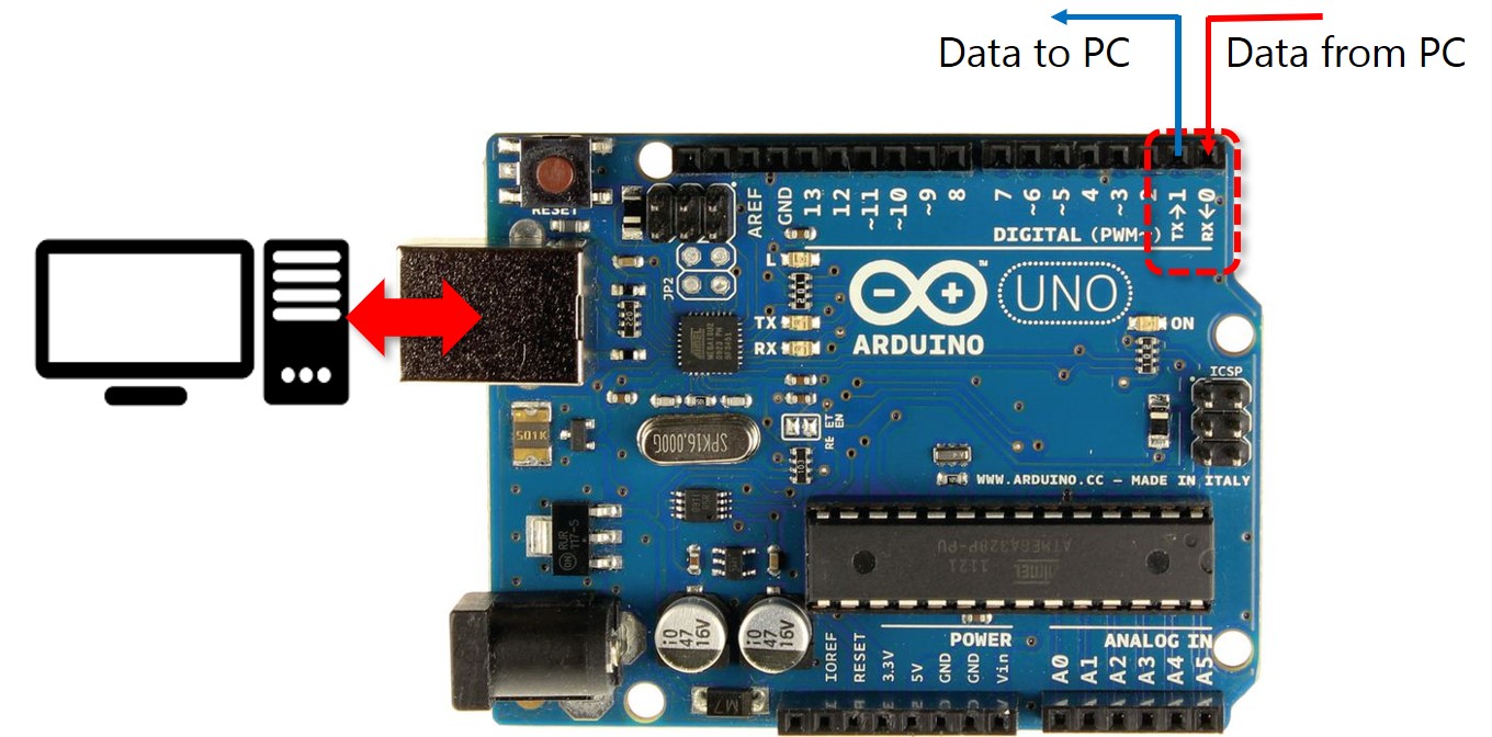
Fig 1. Arduino UNO Rx, Tx pins.
Upload the sketch on Arguino UNO, Tools: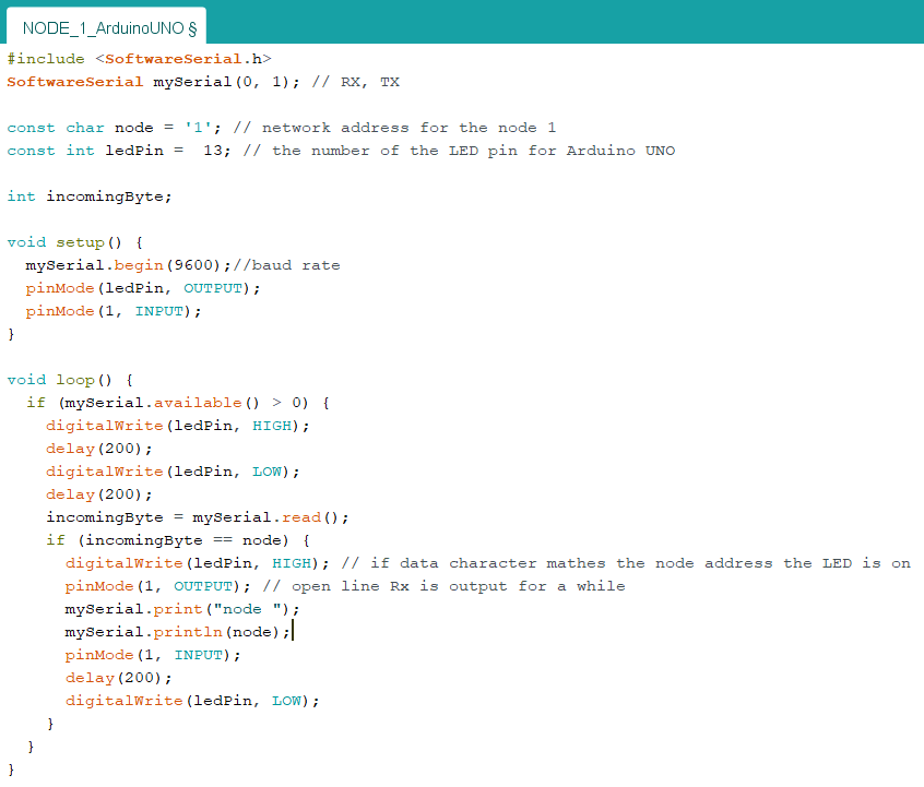
Fig 2. Arduino IDE code for NODE 1.
Typing the node adress in the serial monitor, the node name will be dispalyed and the LED will blink.
The 2 node is my main board with ATmega328P microcontroller. The pins used in the programm:
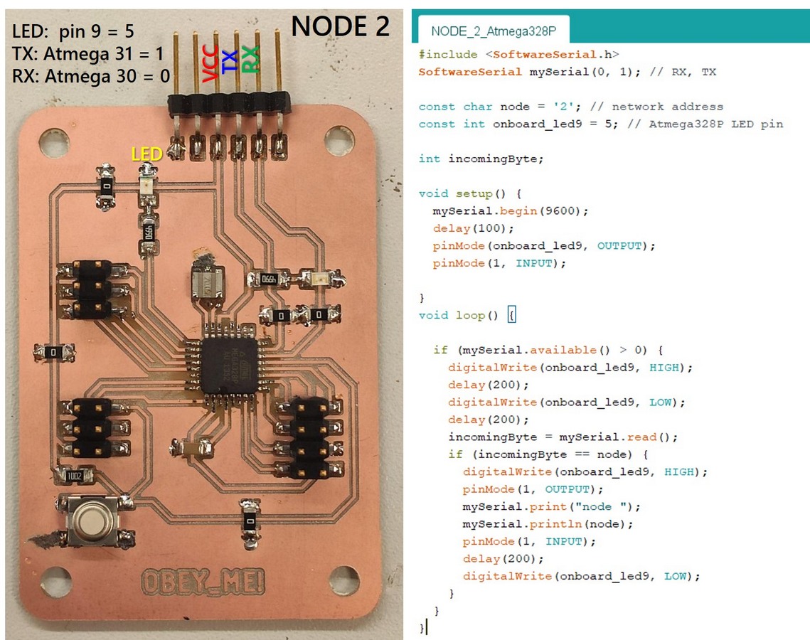
Fig 3. The board on Atmega328P and Arduino IDE code for NODE 2.
Upload the sketch on Atmega328P, Tools:https://raw.githubusercontent.com/carlosefr/atmega/master/package_carlosefr_atmega_index.json
Checking the programm on the Node 2 performance.
Now, when the both nodes were succesfully programmed, I connected them as follows, and connect the Arduino Uno board to the computer with USB cable:
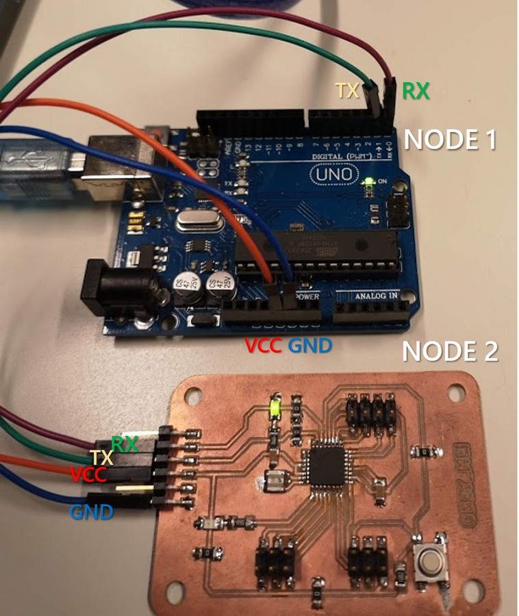
Fig 4. Connection of the nodes.
Finally, I opened the Serial monitor in Arduino IDE: when the node number is sent, the LED on the corresponding board is blinking and the node address appears on the display:
Files:
I wanted to use the Arduino MEGA board instead of Uno, but or some reason, after uploading the sketch, nothing appeared on the serial monitor, when I typed the node number. I also got unlucky as my Attiny412 board was burned, and the Attiny44 was giving really strange outcomes till it stopped responding to my manipulations at all.
