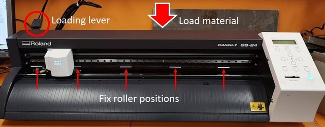
Our instructor this week Behnaz has thoroughly instructed us how to perform the Vinyl cutting procedure.
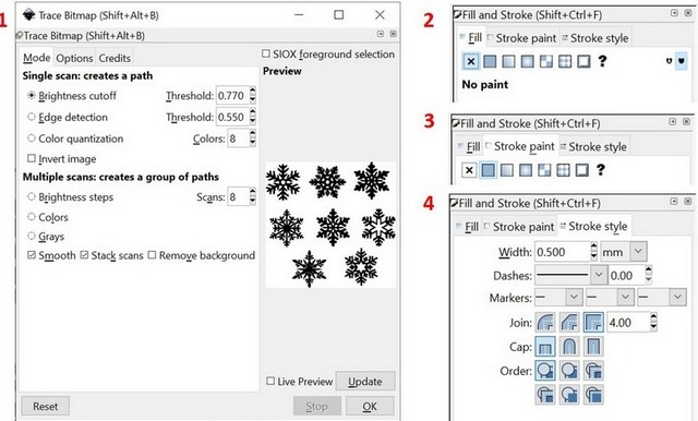
The image for vynil cutting I prepared using Inkscape. First of all I started to look for some nice drawings/templates. Since I miss my home place I decided to go for Siberian style. Including all the stereotypes: bears, spruces and vodka. I have downloaded few images from the internet and decided to combine them in my own way. To get my image I did as follows:
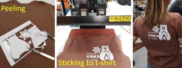
After the cutting was finished I peeled the unwanted parts simply by hands, to remove the smallest pieces I used tweezers. Precision and accuracy of the cut are impressive. From that moment I just had to stick it to the t-shirt, which was easy mentally, but not physically, the press lock is quite hard. I placed the t-shirt in the press machine, waited untill the temperature of the press reach 160 C (I used cotton) and pressed it for 20 sec. When I waited for the sticker to cool down and removed the substrate sheet. Ready!
Parametric design
Parametric design was quite challenging for me, since I was too ambitious with my plans to create something really cool. Well, my ambitions had no match with my skills.
At first, inspired by photos from the internet ( the example), I was certain to design the chandelier. Since I'm vey beginner in Fusion 360 I used the simple tutorial by Keith Christensen to design the phone stand. My first design of the chandelier definietly was not satisfying, it definietly required more elements. The slots I had to add manually. I decided to simplify it and started all over.
Fig 5. "Beautiful" piece of design
Second effort was done to make the small chandelier. The set of parameters of any drawing for laser cutting would necessary include:
- "Material thickness"
- "Kerf" - depends on the physical type of the material and laser settings
- "Slot width = Material thickness - Kerf" and "Slot depth = Value - Kerf"
- "Tab width = Value + Kerf" and "Tab height = Value + Kerf"
Parameters can be set by going to
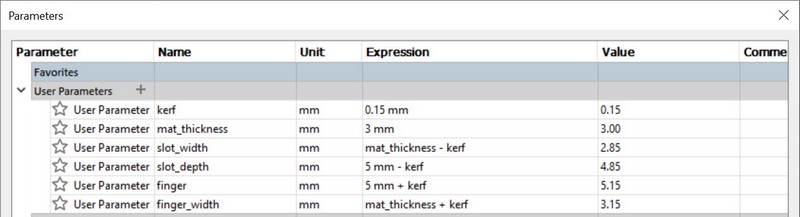
Modify > Change Parameters. My basic parameters for the sketch were as follows on the figure:
Fig 6. Parameters set for the drawing
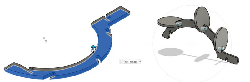
Since I was planning to use MDF 3mm, the material thickness was 3 mm, and the kerf value I used is 0.15 mm. The main parts of the design were 2 circles holding the construction of 5 holders (legs), and the set of 3 different sized leaves to be attached on the holders.
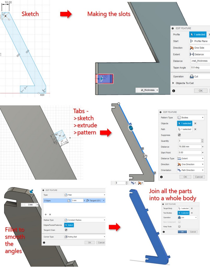
I started from sketching the vertical legs: I made the sketch, added the slots by sketching the slots on the legs and applying the negative Extrude of "-mat_thickness", Operation "Cut". Then I draw 1 tab next to the leg and extruded it to "mat_thickness". The better way would be to create the sketch the tab on the thinner side and then extrude, but better thoughts are coming late sometimes:) To make more tabs along the leg I used Create > Pattern > Pattern on Path.
Fig 7. Basic steps of designing the legs of the lamp
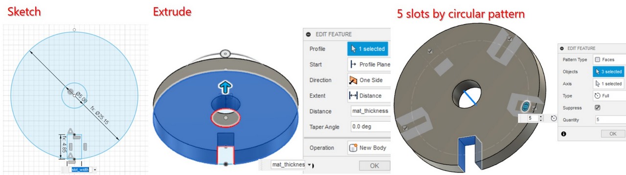
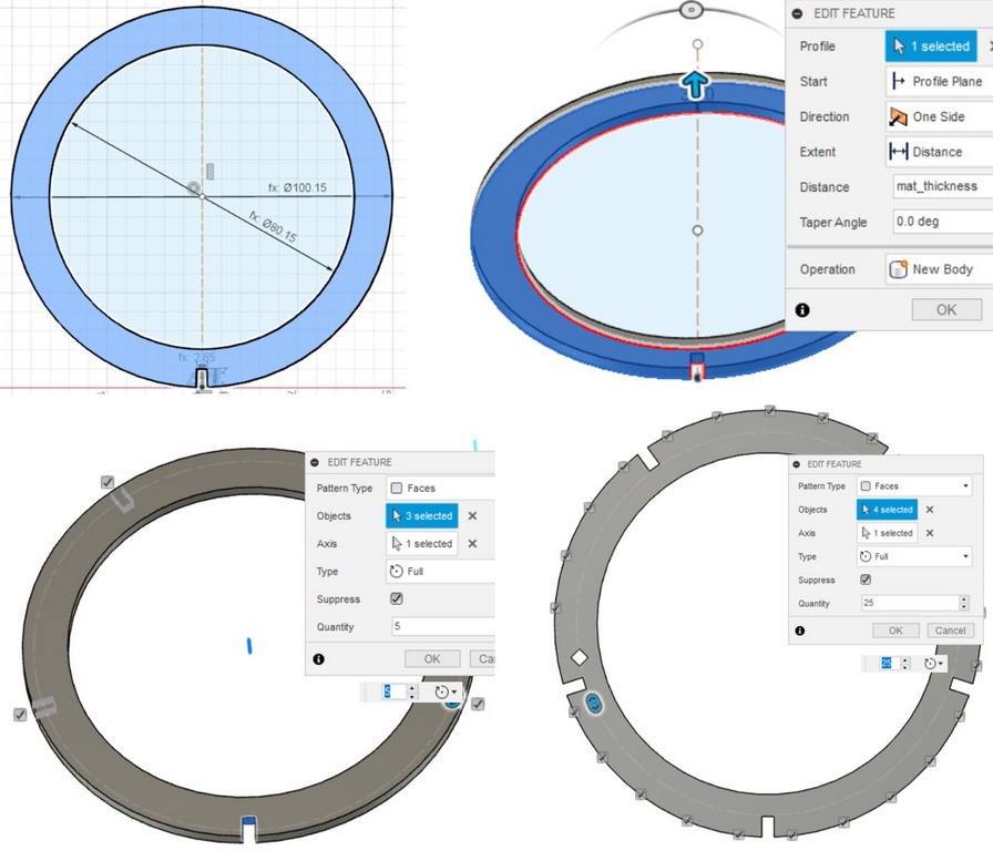
Then I designed the upper and bottom circular holders. I sketched the slots, extruded the "mat_thickness", and then created the circular pattern to make 5 slots. On the bottom bigger holder I added the rectangualr pattern by creating the sketch and adding the pattern.
Fig 8. Basic steps of designing the circular holders of the lamp
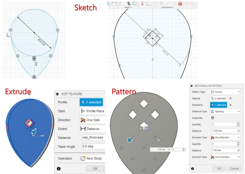
At last I designed the decoration element - the leaves. I made the sketch from the Circle and Fit Point Spline, and removed the unwanted lines with Trim tool. I made 3 different sizes, applyied the Extrude tool, as previously for other parts. At first, leaves were just plain with only one hole. (Just now I realized, that I could have used "hole" parameters instead of "slot" one, and the hole parameter was "material_thickness - kerf"). I decided to add many holes matching the tabs on the holdes, so they can be attached in multiple ways. Having one hole on the leaf, I multiplyed them by going to Create > Rectangular pattern, leaving the holes I wanted to keep. 3 tabs on the holder were also generated after finishing the sketch by Create > Pattern > Pattern on path. So basically for the full chandelier assembly there are 2 circular holders (small and big), 5 legs, and set of 3 types of leaves (5 pieces of each type).
Fig 9. Designing the "leaves" of the lamp.
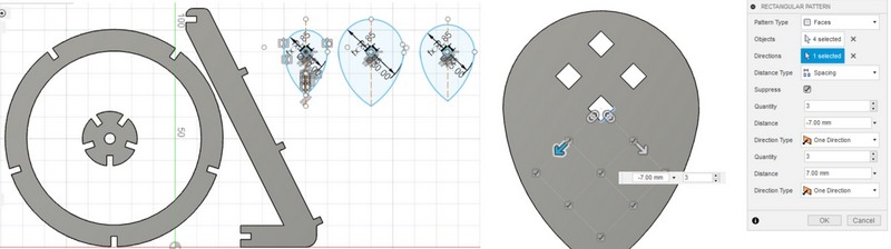
After I finished the design I wanted to create Drawing from design. I had many pieces and I adjusted them by copying and pasting the components, which was kind of messy. Then I got nice fit of all the parts I created the Drawing from design scaled 1:1 and exported it as PDF file. I have opened then this file with Inkscape and changed stroke to 0.02 mm, and exported again as PDF file.
Fig 10. Sketch of the chandelier parts and making the holes with Rectangular pattern
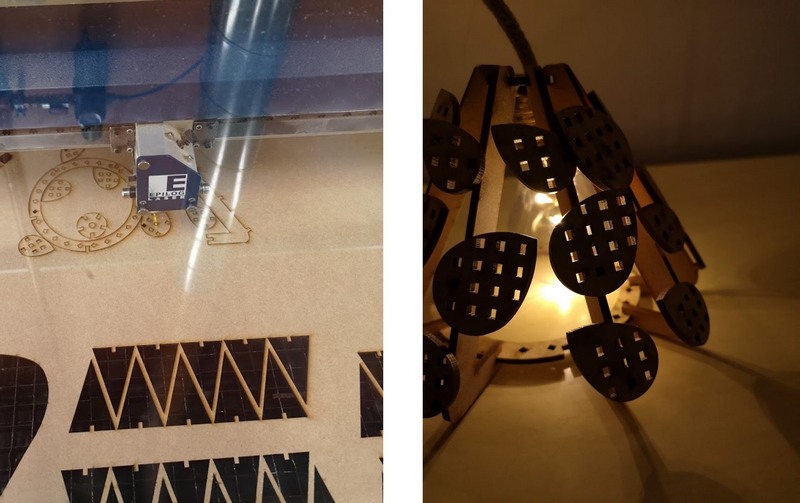
Epilog Fusion M2 40 laser cutter
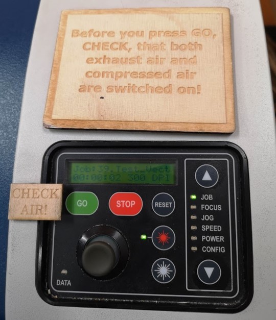
The machine operation starts from turning on switches for the energy and air-exhaust, and then the machine can be started with a power switch. To cut the pieces I used Epilog Fusion M2 40 Laser cutting machine with default settings for MDF 3 mm (Speed = 20%, Power = 100%, Frequency = 20%).
Operation steps:
- The document was sent to print from the PDF file by simply Print or Ctrl+P combination.
- Using the joystick in the Jog mode move the laser to the start point of the cutter.
- Check the Focus adjusting the height with joystick and the calibrator (the tip of the calibrator should slightly touch the surface of the material). Press the Joystick switch to confirm the position.
- Navigating with arrows, in the Job mode select the file and pressGo.
Fig 11. The panel menu of the laser cutting machine
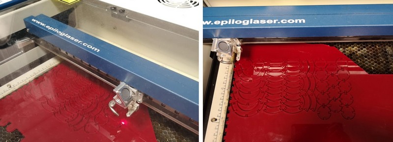
Fig 12. Laser cutting process and the result
Construction kit and laser cutting
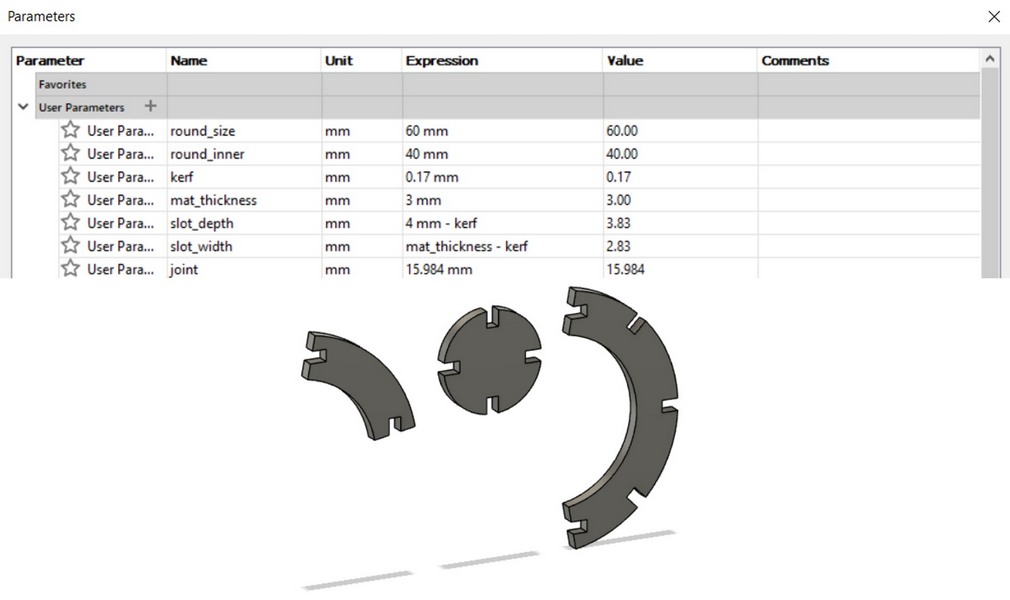
Eventually I wanted to create the construction kit to be assmbled in different ways. I liked the design of this kit and designed one myself parametrically. I did it again in Fusion 360, here is the set of used parameters:
Fig 13. Parameters used for construction kit design and designed parts
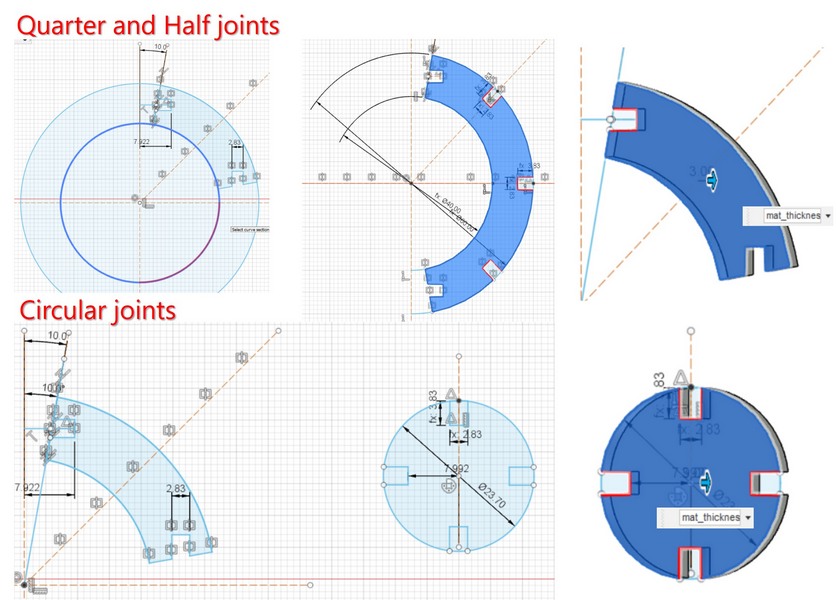
I started from sketcing the circle, cut the sides with a line sketched with 10 degrees incline, added the slots, and extruded the parts. I made half-sphere and quarter (smaller) joints, which are going to be connected with circular joints. Changing of the material thickness or kerf parameters in the design will automatically change the slot widths.
Fig 14. Designing the parts
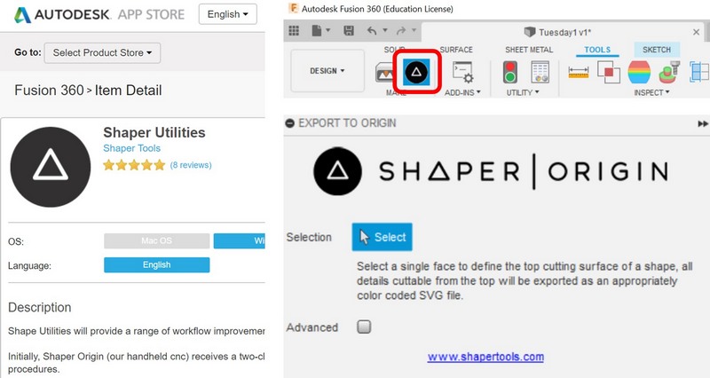
Luckily for me, but not Gleb, I met him in Fablab and he assisted me greatly in cutting procedure and some hints for Fusion, like the Shaper Utilities Plugin he suggested to install. After installation and restarting Fusion 360 it is available in Tools menu. Plugin allows to export any faces of the design as SVG file, which can be after easily modified with Inkscape.
Fig 15. Shaper Utilities Plugin for Fusion 360
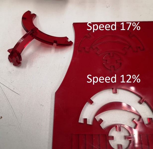
After the first cutting procedure on Epilog Fusion M2 40 I realized I made a mistake in my calculations, then I just simply changed the size of the round connector, and after the second try MDF pieces made a great fit. I wanted to try cutting the same consctruction pieces from the Acrylic 3 mm. First test did not cut through, so I decreased the Speed from 17% to 12%.
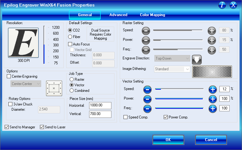
Fig 16. Laser cutting properties for Acrylic 3 mm for Epilog Fusion M2 40
Fig 17. Comparison of Acrylic 3 mm laser cutting with Speed 12 and 17%
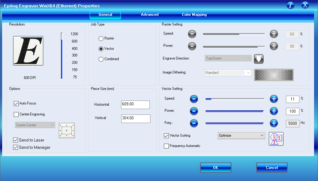
To finish the cutting of the full set from Acrylic I used another laser cutter Epilog Mini 24 with following setting (Speed 11% to ensure the cut through).
Fig 18. Laser cutting properties for Acrylic 3 mm for Epilog Mini 24
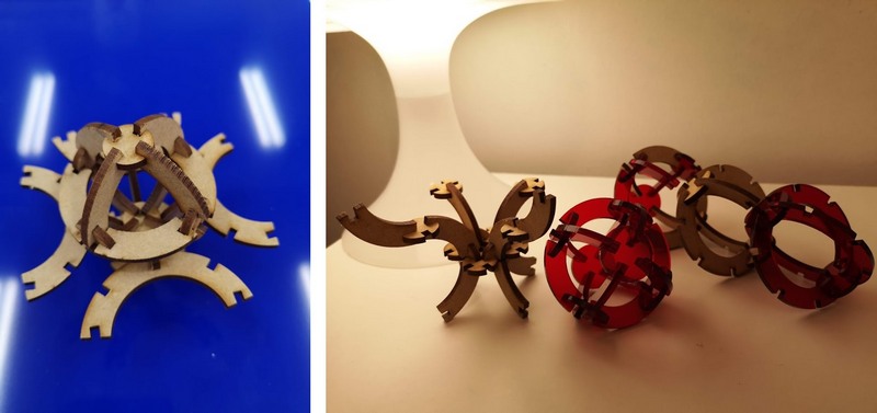
Finally, the kit is ready and can be assembled in different ways.
Fig 19. Construction kit from Acrylic 3 mm and MDF 3 mm materials
FILES:
Reflection
I learned a lot this week, and most of things I did first time as parametric design and laser cutting. Difficulties are mostly concerned the time consumption, beside that there are no problems, instructors were extra helpful.
