While we don't have an access to design our boards, I'm learning the basics with Arduino kit. From the input devices I decided to use Ultrasonic Sensor, even though it doesn't relate to my project.
HC-SR04 Ultrasonic sensor is working in a distance range 2 – 400 cm, with 0.3 cm resolution.
Sensor board has 4 pins:
GND: Ground
VCC: +5VDC
Trig: Trigger (INPUT)
Echo: Echo (OUTPUT)
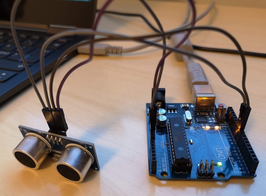
Fig 1. Ultrasonic sensor connected to Arduino UNO board
I skipped using the breadboard, because I didn't connect anything else (LEDs or LCD) at this stage, and connected ultrasonic sensor with jumpers to Arduino UNO as follows:
GND - GND
VCC - 5 V
Trig - Pin 9
Echo - Pin 10
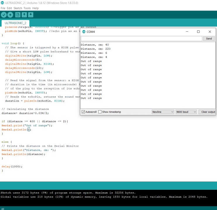
Fig 2. Serial communication with Ultrasonic sensor in Arduino IDE
In this project the ultrasonic sensor reads and writes the distance to an object in the serial monitor. I also set the distance range.
Stepper motor
Unfortunatly, with a quarantine ongoing, I can't proceed well with the design of my own board, therefore, I'm trying to aquire some skills with an Arduino board. In my final project, stepper motor is the key part, therefore during this week I tried to learn some general information about the stepper motors types and their control. Like any other new week in Fabacademy, this one has started with tutorials.
General specifications of Stepper Motors:
Phase. A stepper motor may have several coils but they are wired together and controlled in phases. 2, 4 and 5 phase stepper motors are common.
Step Angle. The amount that the shaft of the motor will spin for each individual full step, measured in degrees.
Voltage. Simply the voltage rating of the motor coils. It is also a function of the current rating and the coil resistance and you can use Ohm’s Law to calculate one from the other.
Current. The maximum current at the rated voltage. This is a useful specification as it will allow you to select a suitable driver and power supply for your stepper motor.
Resistance. The coil resistance, measured in ohms.
Holding Torque. This will be the amount of force that is created when the stepper motor is energized.
Detent Torque. This is the amount of holding torque that can be expected when the motor is NOT energized.
Shaft Style. The physical shape of the motor shaft. You will need to know this in order to mate your stepper motor with gears, pulleys and other external connections such as shaft couplers. There are several common shapes used, in addition, the shaft length can be important for obvious reasons. Most likely I will need "Lead-Screw Shaft", the one shaped like a screw, usually used in constructing linear actuators.
Having some theoretical inderstanding, I started the practice from the simplest step: using the Ardiuno kit and Arduiono IDE to control one of the simplest motors.
Hardware components
28BYJ-48 stepper motor is one of the cheapest motors, which are sutable for learning. Main specifications:
Voltage: 5 V (red wire), consumption around 240mA
Step angle: Half step mode (recommended): 0.0879°
Unipolar
32 steps per rotation internally but has a gearing system that moves the shaft by a factor of 64. The result is a motor that spins at 2048 steps per rotation. Half step mode: 4096 (in reality 4076)
Motor is arranged by 4 coils (four phase stepper motor), which are energized in sequence
ULN2003 driver module is used because usually microcontroller is unable to provide enough current from its I/O pins. The Driver module has 4 LEDs indicating which coil was energised (A,B,C,D), this can be seeing at the low speed.
Arduino UNO
6 wire male-to-female jumpers
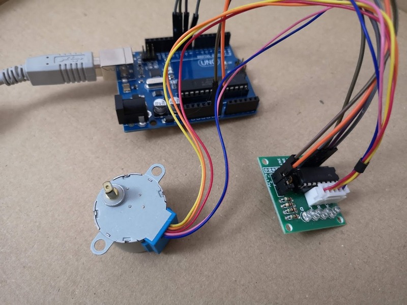
The circuit is very simple: pins 8,9,10 and 11 of Arduino board are connected to IN1,IN2, IN3 and IN4 of the driver respectively. Driver is powered by the 5V pin of the Arduino Board, and of course GND of Arduino to GND of driver. In some tutorials authors energized motors via +5V rail of the Arduino Board, however this approach can damage the board.
Powering the stepper motor directly from the Arduino can damage it!
Therefore, I used External Power supply - powerbank with an 5V output (1.5 A).
Fig 3. Circuit wiring
Stepper.h library
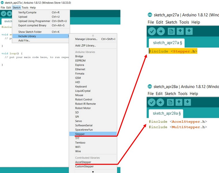
Arduino IDE has own Stepper library, so I started using it. This library takes care of sequencing the pulses, which are sent to the stepper motor, and suitable for a wide variety of motors (unipolar and bipolar).
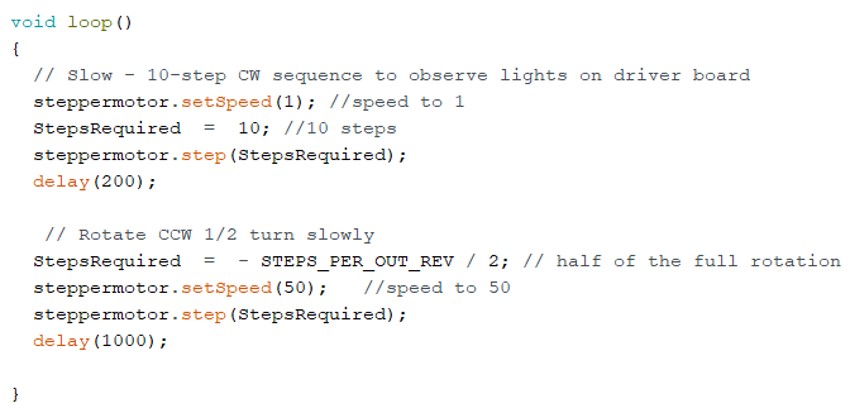
Fig 4. Arduino IDE Stepper Library
In this code I can vary the speed of the motor, number of steps and direction of stepping.
In this sketch the motor is doing 10 steps StepsRequired = 10
clockwise at the lowest speed steppermotor.setSpeed(1), and then it makes steps anticlockwise half of the full rotation
StepsRequired = - STEPS_PER_OUT_REV / 2 with a speed set to 50.
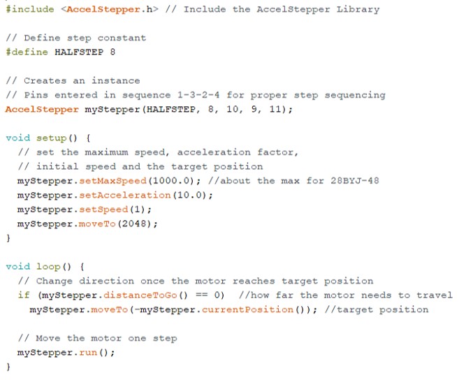
Fig 5. Arduino Sketch with Stepper AccelStepper library
The stepper is moving with a speed 1 (movements are hardly observed, can be indicated by the LEDs on the Driver modile), and then anticlockwise with a speed 50. Arduino IDE Stepper Library
Since my first interest is very low speed, I set it to 1. This results in very discrete steps, meaning that speed control is not the problem, but the step size.
The Driver module has 4 LEDs indicating which coil was energised (A,B,C,D), this can be seeing at the low speed.
Half-stepping with AccelStepper lib
Another try I made with a library made by Mike McCauley, which supports half-step driving.
The example was taken from here and modified to perform the half-stepping.
This sketch accelerates the stepper motor in one direction and then decelerates to come to initial position, and then the cycle repeats in another direction. Still, the steps are very discrete at the lowest speed (1).
Fig 6. Arduino Sketch with AccelStepper library
Motor control with joystick
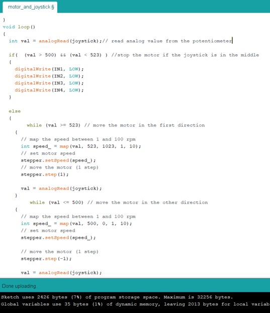
Joystick VRx output is connected to Arduino A0. This code I can modify lately to program the control of two stepper motors independently (X-axis and the Y-axis potentiometers). There are 3 intervals:
1) 500 and 523: joystick is released and the stepper motor is not moving at all (all outputs are low).
2) digital value ≥ 523: motor moves in the first direction. Speed map 1 to 100 rpm.
3) digital value ≤ 500: motor moves in the other direction. Speed map 1 to 100 rpm.
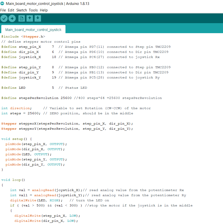
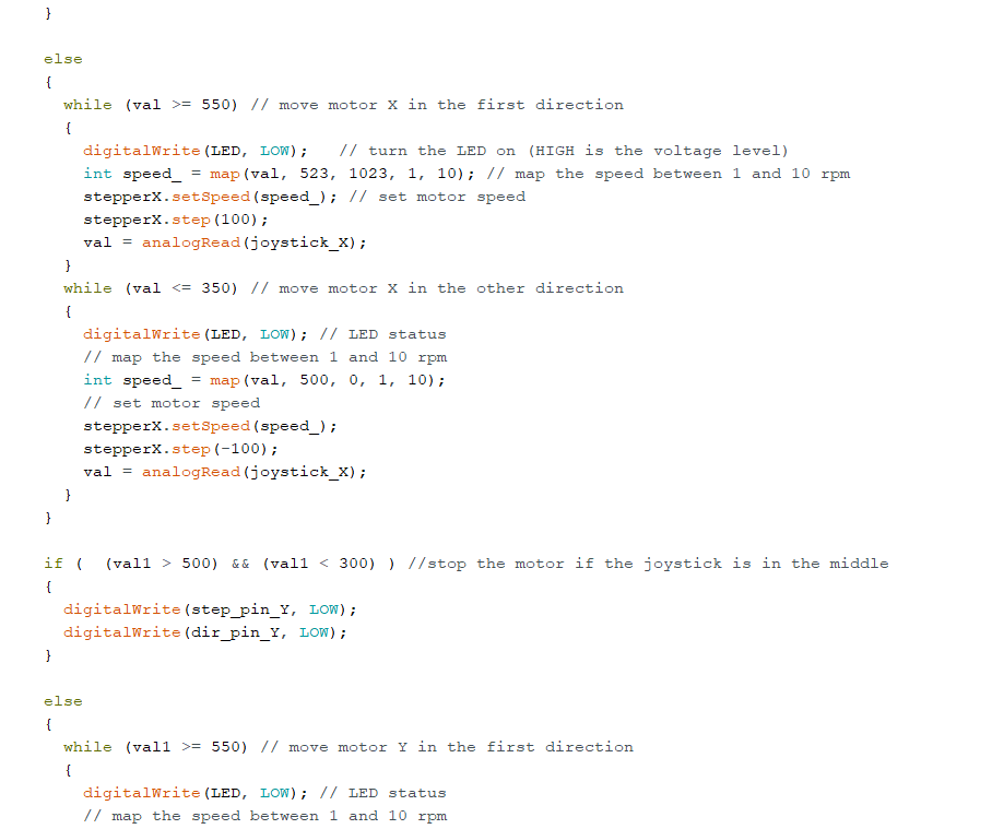
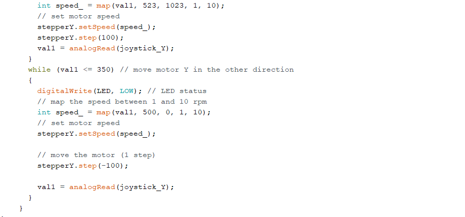
Fig 7. Sketch to control the stepper motor with joystick
Control of the direction of stepper motor rotation (X axis) with joystick
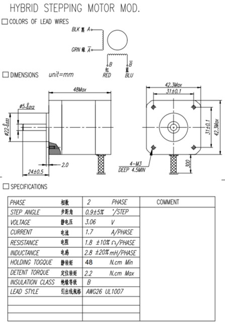
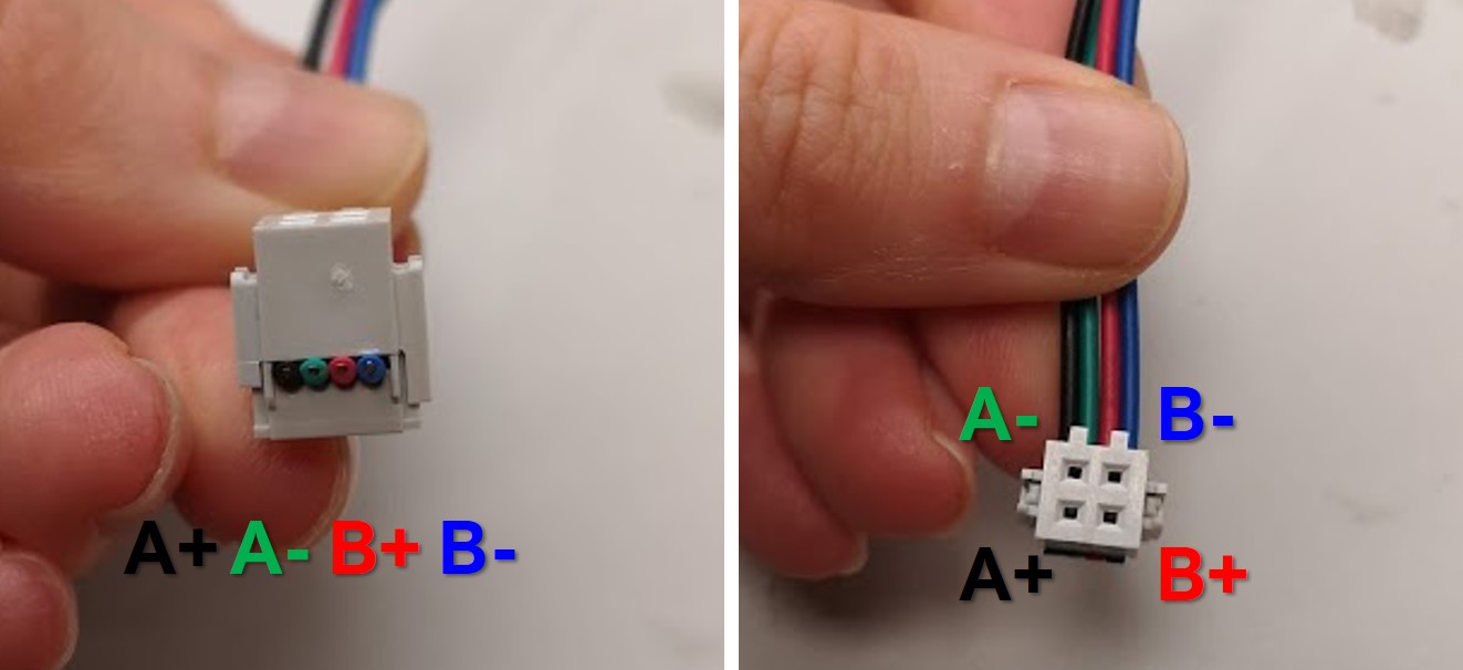
Fig 8. ROB-10846 bipolar stepper motor from SparkFun specifications
There are 4 wires connected with coils: The cables were not crimped, so I used 2×2-pin cable connector to arrange them. Cables should be placed the desired order, and then header can be closed with a table clamp.
Fig 9. Placing motor's wires into the 2×2-pin crimp housing connector
TMC2209 stepper motor driver
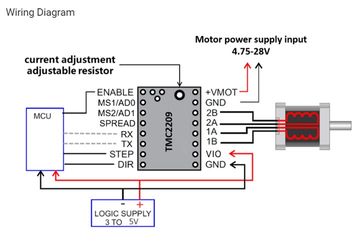
Among all the stepper motor drivers, my choice went to one of the newest version of TMC driver from Trinamic. The main reason - it is one of the best for my particular purpose - to achieve slow, but smooth motion. But it provides much higher step resolution up to 1/256 steps, UART communcation, it is more precise and less noisy. Here is the convinsing test comparison of the A4988, DRV8825 and TMC2100 drivers. One important difference is that pin EN is connected to GND to enable motor outputs.
There are 2 most important pages with all the specifications of the TMC2209 TMC2209 characteristics, and TMC silentstick. Essentially, working principle of TMC2209 doesn't differ from it's cheaper analogs like DRV8824 and A4988.
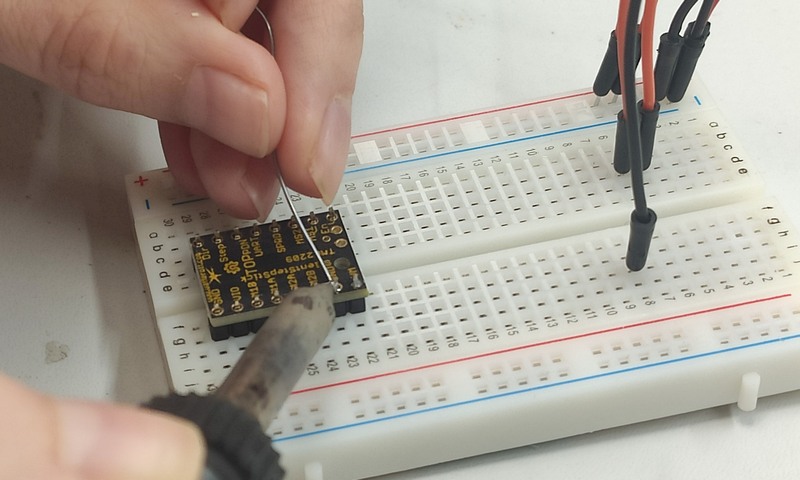
The board carrier of TMC microcontroller comes with 0.1″ male header pins included, but not soldered in. At first, I soldered the headers.
Fig 11. Soldering the headers on the TMC2209 board
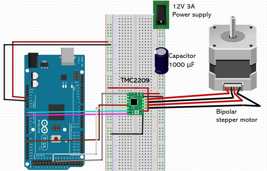
Stepper motor joystick control PCB
At first, I had to check the performance of the driver by connecting it with the stepper motor via breadboard and using Arduino board as a controller. At a very first step I faced the problem, for some reason, available examples for TMC2209 were made for Arduino Mega, and the attempt to run it on Arduino UNO was not successful. My friends Gleb and Masha have decided it is the time for a future birthday present, so here I am with a new Arduino Mega board!;) The connections and corresponding pins are on the following images.
When I started general search on TMC2209, I couldn't not to notice the link How to not kill a stepper driver? From that topic's chat I took some advices: do not disconnect a stepper motor when drivers are enabled and the current is passing through the coils. Good to keep it in mind and be cautious.
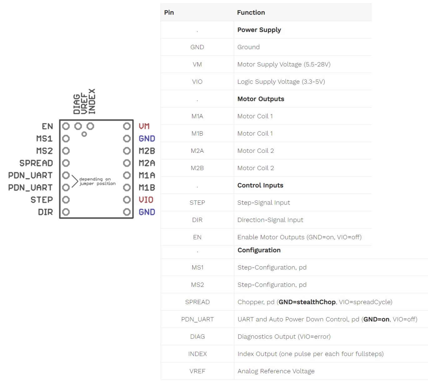
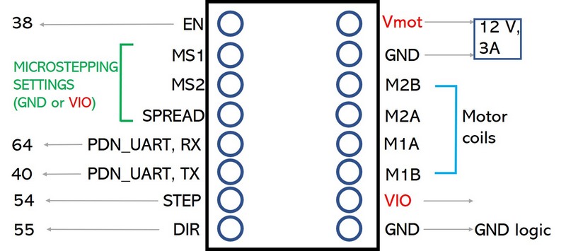
Pin functions mapping:
Fig 12. TMC2209 pins connections with Arduino Mega board. I made the approximate wiring in Fritzing. There was no TMC driver available, so I slightly modified the available A4899 to TMC2209
There is a Library available for TMC series drivers on GitHub. Therefore I download the ZIP files of the project > Open Arduino IDE > Sketch > Include Library > Add ZIP Library... > Add archive > the library "TMCStepper" will appear on the libraries list.
Among the examples I opened the "StallGuard_TMC2209.ino" by Teemu Mäntykallio. The pins were connected to the corresponding pin numbers from the code.
I just used my pin numbers in the code StallGuard_TMC2209. This code is allowing serial communication, stepper motor rotates faster by sending + via Serial monitor, slower with -, 0 will stop and 1 resume rotation. The code works great, however it is too complicated for my purpose. The final code for the motor is on the Project development page for 2 motors.
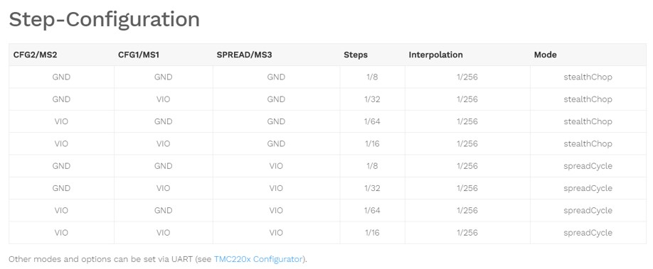
Fig 13. Configurations for microstepping settings
To achieve the smoothest rotation of the stepper motor, I had to activate the microstepping. TMC2209 has StealthChop2 technology that ensures the noiseless operation, maximum efficiency and best motor torque, so I sticked to that. Following the table I tried different options of microstepping. 1/64 step mode is the highest mode, which can be set manually: this mode provides very slow, smooth and almost silent rotation.
Sample code on Arduino Mega running the rotation of the stepper motor with TMC2209 motor driver
Input: Joystick motor control PCB
Our instructor Ivan Milara advised me to make the separate board for motor's drivers, which then will be controlled from the main board. The pages of our previous students who used stepper motors in the projects were very helpful, I used Ari's Vuokla and Yasir's Shafiullah pages. PCB design and fabrication are described on the Progect development page.
Motor board incorporates stepper motor drivers, and then EN (enable), DIR (direction), and STEP pins are connected with the Atmega328P microcontroller pins on the main board.
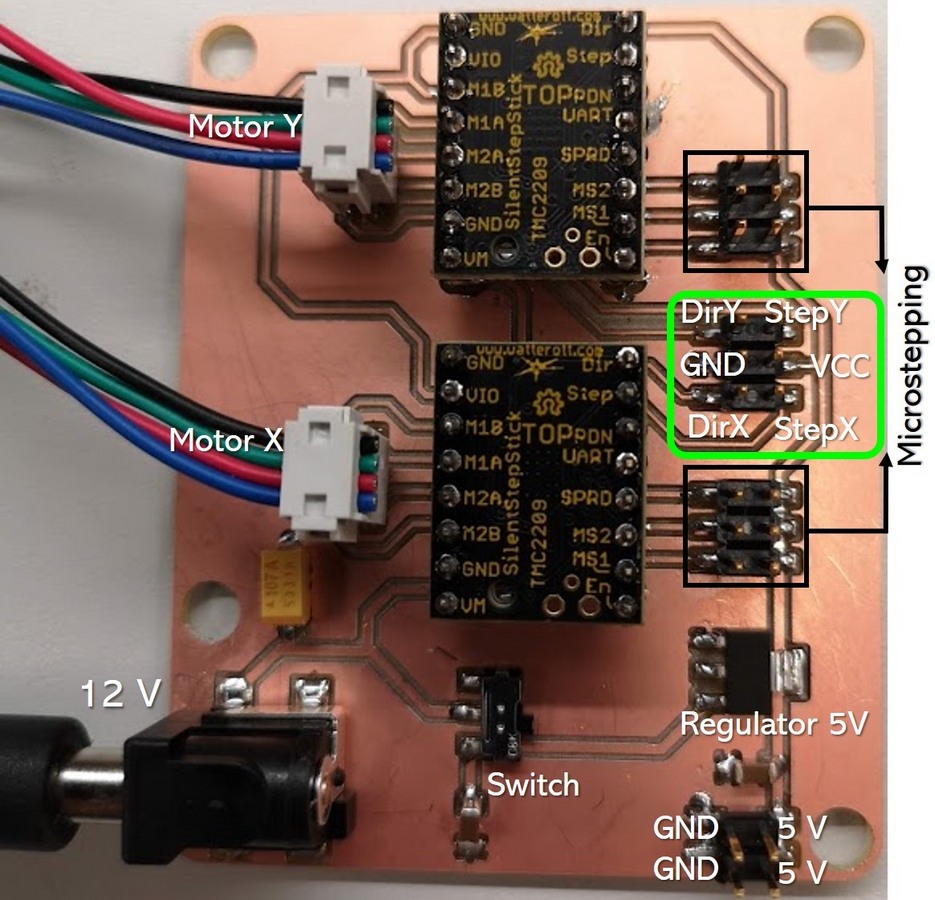
Fig 14. Motor board with TMC2209 drivers
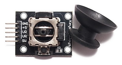
I used the simple XY Dual Axis Joystick Module from the Arduino kit. Joystick module has the power pins 3.3-5V and GND, 2 analogue outputs VRx and VRy (Variable Resistance), and the push button SW (switch) digital pin that activates when you push the joystick down. In principal joystick has two potentiometers one for vertical movement and one for horizontal movement. When 5V is applied at one end of the potentiometer and 0V at the other end of the potentiometer, and the wiper adopts a value in between these voltages, while analogue values can be read.
Fig 15. XY dual axis joystick module
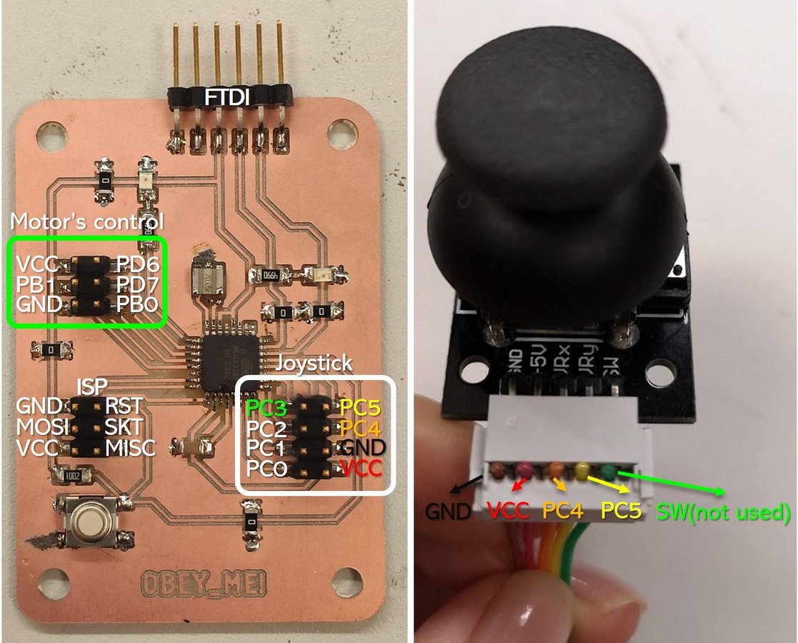
I used the Joystick button as an input device to control the stepper motors through the Atmega328P microcontroller on the Main board. The 2x5-pin crimp housing connector was used to place 5 wires from the joystick and connect them with the main board.
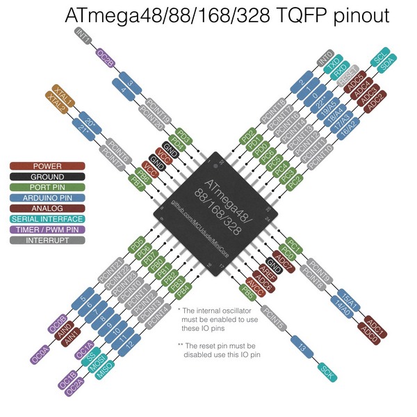
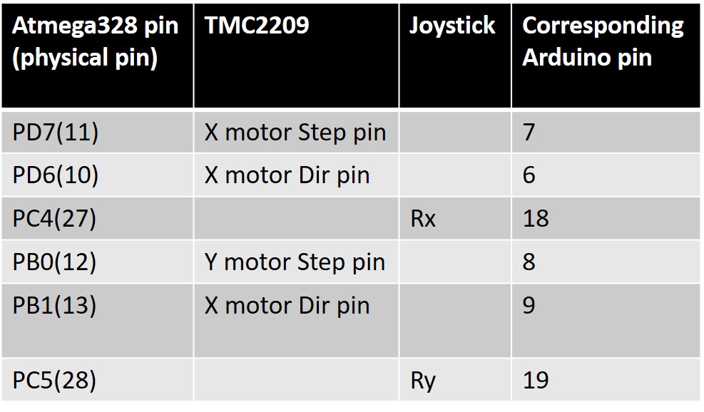
Using the Atmega328P pinout, the pins were connected as follows in the table:
Fig 18. Pin connections
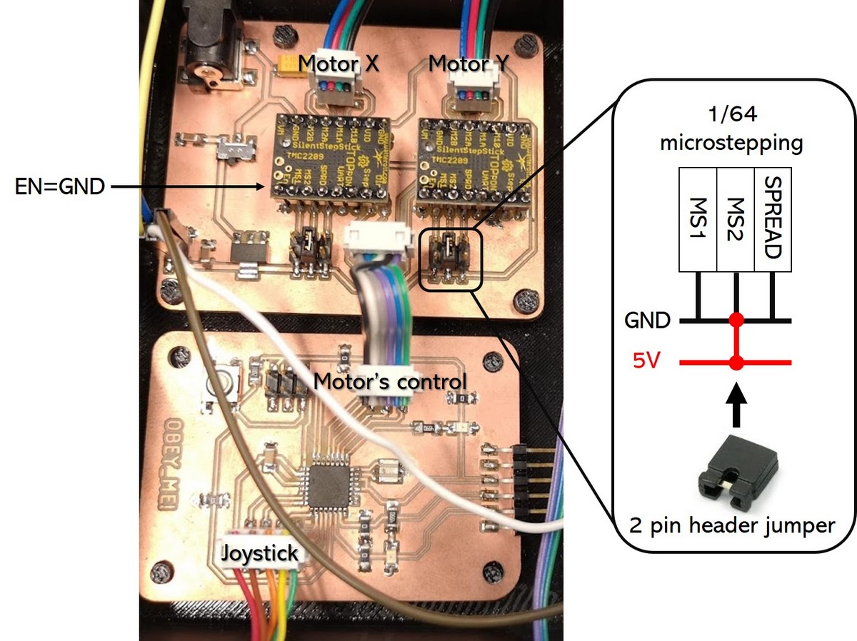
Fig 19. Connected boards. Motor Enable function and microstepping are configured in hardware
From the pin functions table of TMC silentstick the EN(enable) Enable motor outpus GND=on, VIO=off. Therefore the EN pin of the drivers on the motor board connected to the GND are enabled by default. Motors are making 25600 steps per 1 revolution = initial 400 steps per revolution × 64 (microstepping), by connecting SPREAD=GND, MS1=VIO, MS2=GND. So basically the EN and microstepping functions of the drivers are set in hardware.
In the code I used the built-in Stepper.h library. Then I defined the stepper motor control pins from the table above for motor X and Y, and joystick pot outputs.
After defining the pins, in the loop section, the joystick X and Y axis values are read; the analog inputs connected with board have values from 0 to 1023. When joystick is in the center position these values for X and Y axes are around 512. In the code I used some tolerance - the center was set between 300 and 500.
When the Y or X axis of the joystick is moved backward the values go below 350, while moving the joystick X and Y forward values go above 550. These reading are convert then into the rpm (1 to 10 rpm).
This week I spent time understanding the pronciple of the stepper motors - the basic component for my final project. With plenty of the collected information it is the time to define, which motor type I should use to provide high precision, smooth and slow stage motion.