Individual Assignment
This week's individual assignment is about adding a sensor to a microcontroller board to detect signals from the environment. In my final project, I will need a Hall Effect sensor to adjust the zero point of the clock hand. Thus, for this week's assignment, the Hall Effect Sensor will be integrated with the ATtinty 1614 board.
Board Design
In my final project, a unipolar stepper motor will be used to control the clock hand movement. The unipolar stepper does not have default starting point, which requires the zero point to be calibrated whenever the devices is initiated.

In this case, the Hall Effect sensor can be an ideal solution.
According to Wikipedia:"A Hall effect sensor is a device that is used to measure the magnitude of a magnetic field. Its output voltage is directly proportional to the magnetic field strength through it."
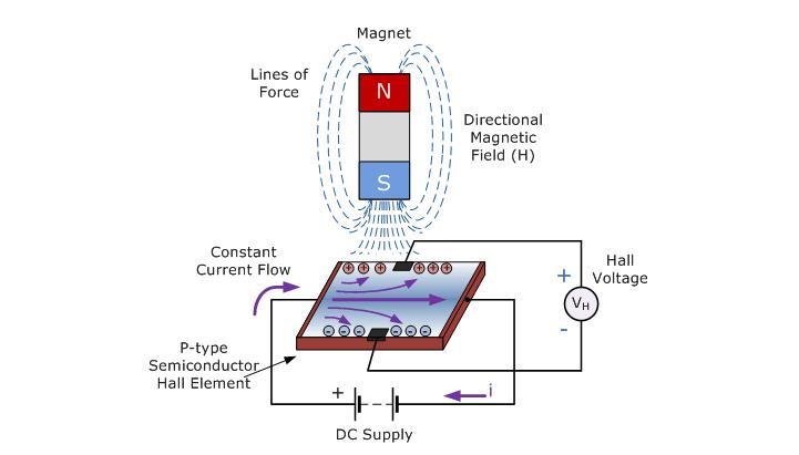
My plan is to place a strong magnet on the clock hand and place the Hall Effect sensor on the back of the clock face at the zero point. The clock will rotate a full revolution when it is turned on until it detects the strongest magnetic field. That point will be labeled as the zero point, from which the step counting starts.
In my design, the sensor is placed on a separated board that connects to the microcontroller board with wires. This is because that the Hall Effect sensor can only detect the magnetic field that approaches from a certain direction. It will be much harder to adjust the direction if the sensor is on a large board with all other components, while the other components and wires themselve can generate magnetic fields.
ATtiny 1614 Board
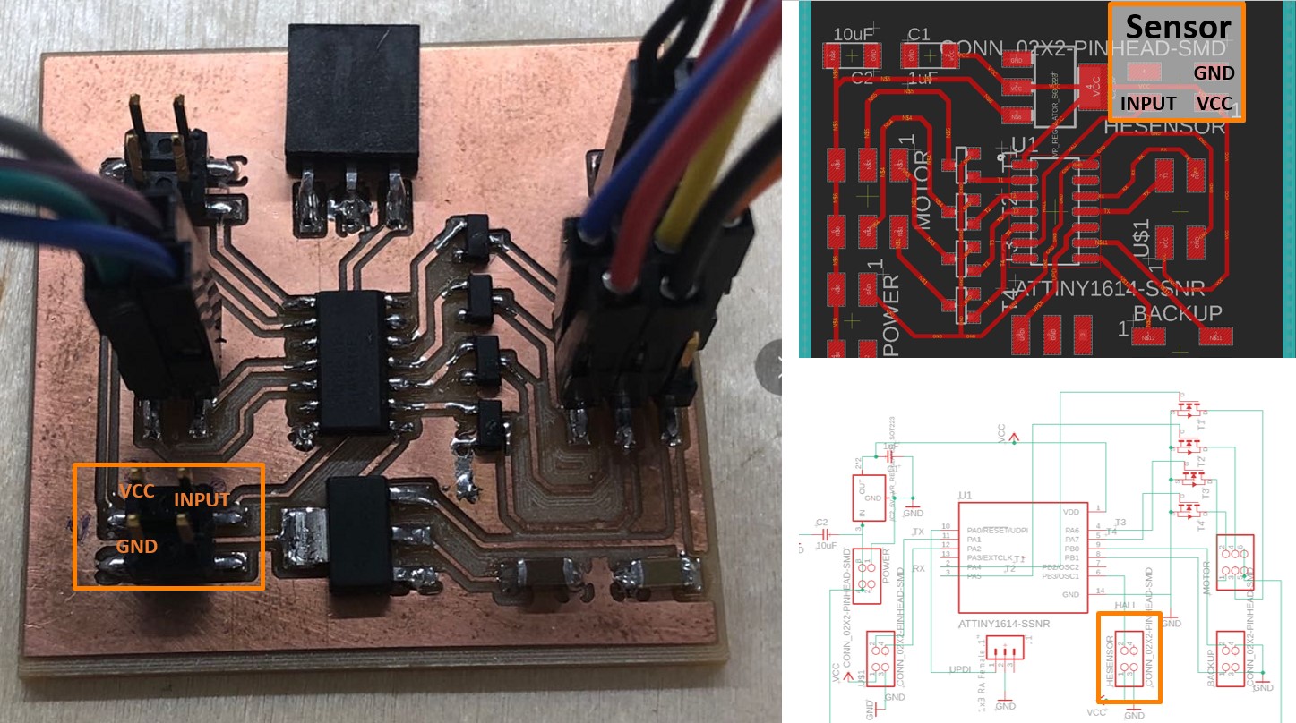
On my microcontroller board, I have reserved a digital pin (PB3) of the ATtiny 1614 chip for receiving the sensor input and have connected the VCC and GND to the connectors that designated for the sensor communication. More design details of this microcontroller board can be found here.
Hall Effect Sensor Board
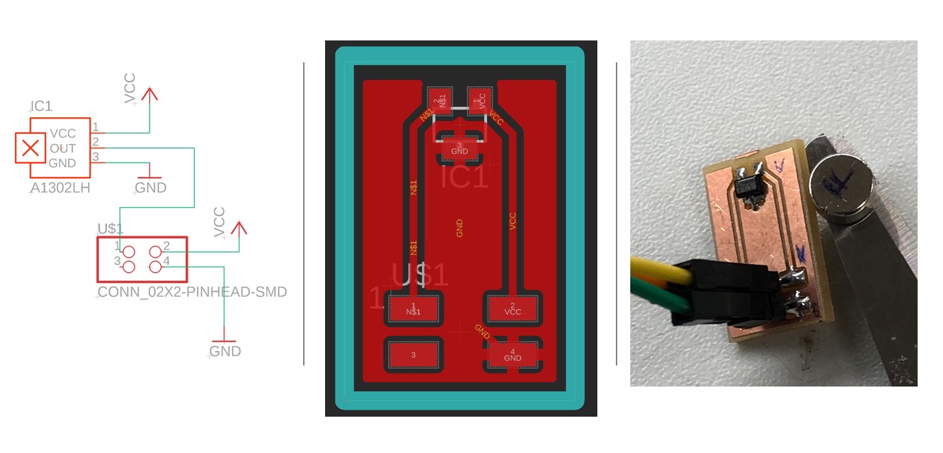
The Hall Effect sensor board is very simple, which basically have only two components: a Hall Effect sensor and a connector that connect the three pins of the sensor.I used a SOT23-W Hall Effect Sensor and a 2x2 connector in this case.
I intentionally left a relatively large space between the sensor and connector to prevent the detection being interfered by the magnetic field
Sensor Measurement
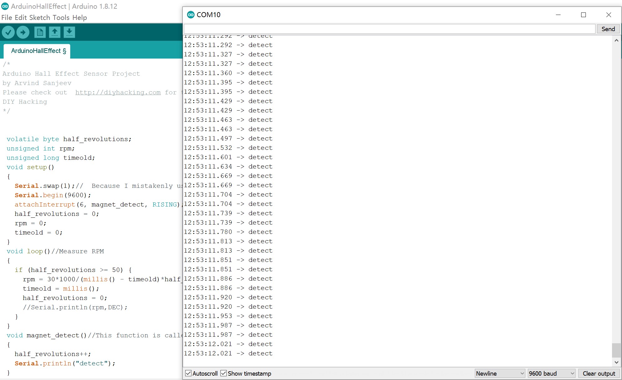
In my case, the precision of the signal detection was not as crucial as let the sensor being able to detect the signal per se. Thus, I used the following code that I retrieved from this tutorial as a start. This tutorial was based on Arduino Uno board, but the code works well for the ATtiny 1614 board with simple modification.
             /*

            Arduino Hall Effect Sensor Project

            by Arvind Sanjeev

            Please check out  http://diyhacking.com for the tutorial of this project.

            DIY Hacking

            */


             volatile byte half_revolutions;

             unsigned int rpm;

             unsigned long timeold;

             void setup()

             {

               Serial.swap(1);//  Because I mistakenly used the back up Rx/Tx on my board

               Serial.begin(9600);

               attachInterrupt(6, magnet_detect, RISING);//Initialize the intterrupt pin (Pin 6 of ATtiny 1614)

               half_revolutions = 0;

               rpm = 0;

               timeold = 0;

             }

             void loop()//Measure RPM

             {

               if (half_revolutions >= 50) {

                 rpm = 30*1000/(millis() - timeold)*half_revolutions;

                 timeold = millis();

                 half_revolutions = 0;

                 //Serial.println(rpm,DEC);

               }

             }

             void magnet_detect()//This function is called whenever a magnet/interrupt is detected by the arduino

             {

               half_revolutions++;

               Serial.println("detect");

             }
This code works well. As the magnet approaches to the sensor, the sensor can detect the magnetic field and print "detect" in the serial port.
For the final project, the Hall Effect sensor is used to determine the zero point. The mechanism is like:
1. The clock hand starts to rotate in the clockwise direction
2. The Hall Effect Sensor is placed at the back of the clock face to detect the magnetic field when the clock hand get near enough
3. When the microcontroller receive the "detect" signal from the sensor, it will set that position as the start point.
* My original plan was to make this progress iterative: I was considering make a comparison of the magnetic field magnitude for each step, which will allow me to determine which point has the strongest signal and hence determine the start point more precisely. However, I soon found it is much easier to adjust the distance between the clock hand and sensor to reduce the error due to detection range.
Thus, as shown below, the code I used for the clock only determine two conditions: detected vs not-detected.
Hall Effect Sensor Relevant Code
             int currentstep = 0;

                //Hall Effect

                int hallsensor = 4;//pin PB3

                int digitalVal;//digital readings

                void setup() {

                    //...omited irrelevant code

                    pinMode(hallsensor,INPUT);


                      while (true){

                        step(1);

                        digitalVal = digitalRead(hallsensor);

                        if (digitalVal==LOW){ //low = detect

                          break;

                        }

                        else{

                          }

                      }

                      currentstep=0;

                    }
              Motor Control Code


                const int T4_Blue = 3;
                const int T1_Black = 0;
                const int T3_Red = 2;
                const int T2_Yellow = 1;
                const int maxnumberofsteps = 48;

                int currentstep = 0; // Indicates in which step I am (0,47)-> your motor do 48 steps in one rotation
                int current_location = 0; // Indicates in which position I am (0 to 11)
                int num_of_steps = 0;
                String inString = "";

                #define step_delay 500

                void stepMotor(int step_t) {
                   switch (step_t) //
                  {
                    case 0:
                    //Serial.println("Yellow/Red HIGH");
                       digitalWrite(T4_Blue, LOW);
                       digitalWrite(T1_Black, LOW);
                       digitalWrite(T3_Red, HIGH);
                       digitalWrite(T2_Yellow, HIGH);

                    break;

                    case 1:
                       digitalWrite(T1_Black, HIGH);
                       digitalWrite(T3_Red, HIGH);
                       digitalWrite(T2_Yellow, LOW);
                       digitalWrite(T4_Blue, LOW);

                    break;

                    case 2:
                       digitalWrite(T4_Blue, HIGH);
                       digitalWrite(T1_Black, HIGH);
                       digitalWrite(T3_Red, LOW);
                       digitalWrite(T2_Yellow, LOW);
                    break;

                    case 3:
                       digitalWrite(T4_Blue, HIGH);
                       digitalWrite(T1_Black, LOW);
                       digitalWrite(T3_Red, LOW);
                       digitalWrite(T2_Yellow, HIGH);
                    break;

                  }
                 // Serial.print("step_t ");
                  //Serial.print(step_t);
                 }

                // Move x steps (negative will move backwards)
                void step(int steps_to_move)
                {
                  int steps_left = abs(steps_to_move);  // how many steps to take

                  int direction = 0;

                  // determine direction based on whether steps_to_mode is + or -:

                  if (steps_to_move > 0) {
                    direction = 1;
                  }

                  if (steps_to_move < 0) {
                    direction  = 0;
                  }

                  // decrement the number of steps, moving one step each time:

                  while (steps_left > 0)

                  {

                    // increment or decrement the step number,

                    // depending on direction:

                    if (direction == 1)

                    {
                      currentstep++;

                      if (currentstep == maxnumberofsteps) {
                        currentstep = 0;
                      }
                    }
                    else // direction==0
                    {
                      if (currentstep == 0) {
                        currentstep = maxnumberofsteps;
                      }
                      currentstep--;
                    }
                    // decrement the steps left:
                    steps_left--;

                    // step the motor to step number 0, 1, ..., {3 or 10}
                    stepMotor(currentstep % 4);
                      //Serial.print("Stepleft: ");
                  //Serial.println(steps_left);
                  delay (step_delay);
                  }

                }

                //Move to position
                void moveToLocation(int location){
                  num_of_steps = (location - current_location)*4; // Each location is 30 degrees. You have then 4 steps per locations

                  current_location = location;
                 Serial.print("steps: ");
                 Serial.println(num_of_steps);
                  step (num_of_steps);
                  }


                void setup() {

                  pinMode(T4_Blue, OUTPUT);
                  pinMode(T1_Black, OUTPUT);
                  pinMode(T3_Red, OUTPUT);
                  pinMode(T2_Yellow, OUTPUT);
                  Serial.swap(1);
                  Serial.begin(9600);
                  step(5);


                  currentstep=0;
                }

                void loop() {

                // put your main code here, to run repeatedly:
                    //for location10, 11 and 12, which are more than 1 byte
                  while (Serial.available()>0) {
                   int inChar = Serial.read();
                    if (isDigit(inChar)) {
                      // convert the incoming byte to a char and add it to the string:
                      inString += (char)inChar;
                    }
                    // if you get a newline, print the string, then the string's value:
                    if (inChar == '\n') {
                      //Serial.print("Value:");
                      int location = inString.toInt();
                      //Serial.println(location);
                      //Serial.print("String: ");
                      //Serial.println(inString);
                      // clear the string for new input:

                      inString = "";//

                      Serial.print("location: ");
                      Serial.println(location);
                      moveToLocation(location);
                      //step(location);
                    }
                  }
                /*
                for (int i=0; i<=48; i++){ //It should do ¼

                Serial.println(i);

                stepMotor(i%4); //module result from 0 to 4

                delay(2000);

                Serial.println("Moving 12");
                step(12);
                delay (5000);
                Serial.println("Moving 24");
                step(24);
                delay(5000);
                Serial.println("Moving 48");
                step(48);
                delay(5000);

                Serial.println("location 3");
                moveToLocation(3);
                Serial.println(current_location);
                delay (5000);
                Serial.println("location 5");
                moveToLocation(5);
                Serial.println(current_location);
                delay(5000);
                Serial.println("location 11");
                moveToLocation(11);
                Serial.println(current_location);
                delay(5000);
                Serial.println("location 6");
                moveToLocation(6);
                Serial.println(current_location);
                delay(5000);*/

                }
Group Assignment
This week's group assignment is to probe an input device's analog levels and digital signals. Our group tested the digital and analog signal of a Hall Effect Sensor, which mostly due to the easiness of the circuit and the obvious effect.
Hall Effect sensor can detect the magnetic field that approach from a certain direction, which can be reflected via different voltage. For convenience, we used an Arduino UNO board and a Hall Effect sensor board from one of our programs for this group assignment.
The board connection and is again derived from this tutorial
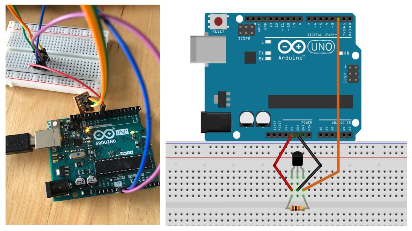
We have used really simple code to detect the digital and analog signals from the sensor. The main structure of the code are basically the same, except the usage of digital pins versus analog pins.
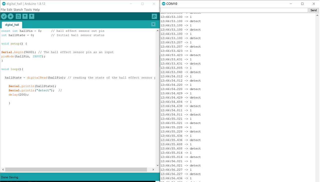
1.Digital Detection
In this case, one of the digital pins is used for Hall effect sensor input. There are two status of the sensor input: HIGH and LOW, which corresponds to the status of "detected" versus "not detected".
The code used is as below:
            const int hallPin = 0;     // hall effect sensor out pin

            int hallState = 0;         // Initial hall sensor status


            void setup() {


            Serial.begin(9600); // The hall effect sensor pin as an input

            pinMode(hallPin, INPUT);

            }


            void loop(){


              hallState = digitalRead(hallPin); // reading the state of the hall effect sensor pin


                Serial.println(hallState);

                Serial.println("detect");  //

                delay(200);


                }
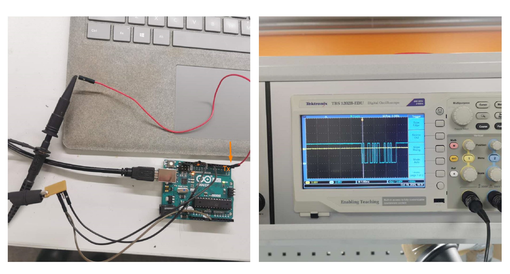
We also used the oscilloscope to detect the digital wave of the sensor. We have measured the signal from the Tx pin of the board and detected the square wave on the screen.
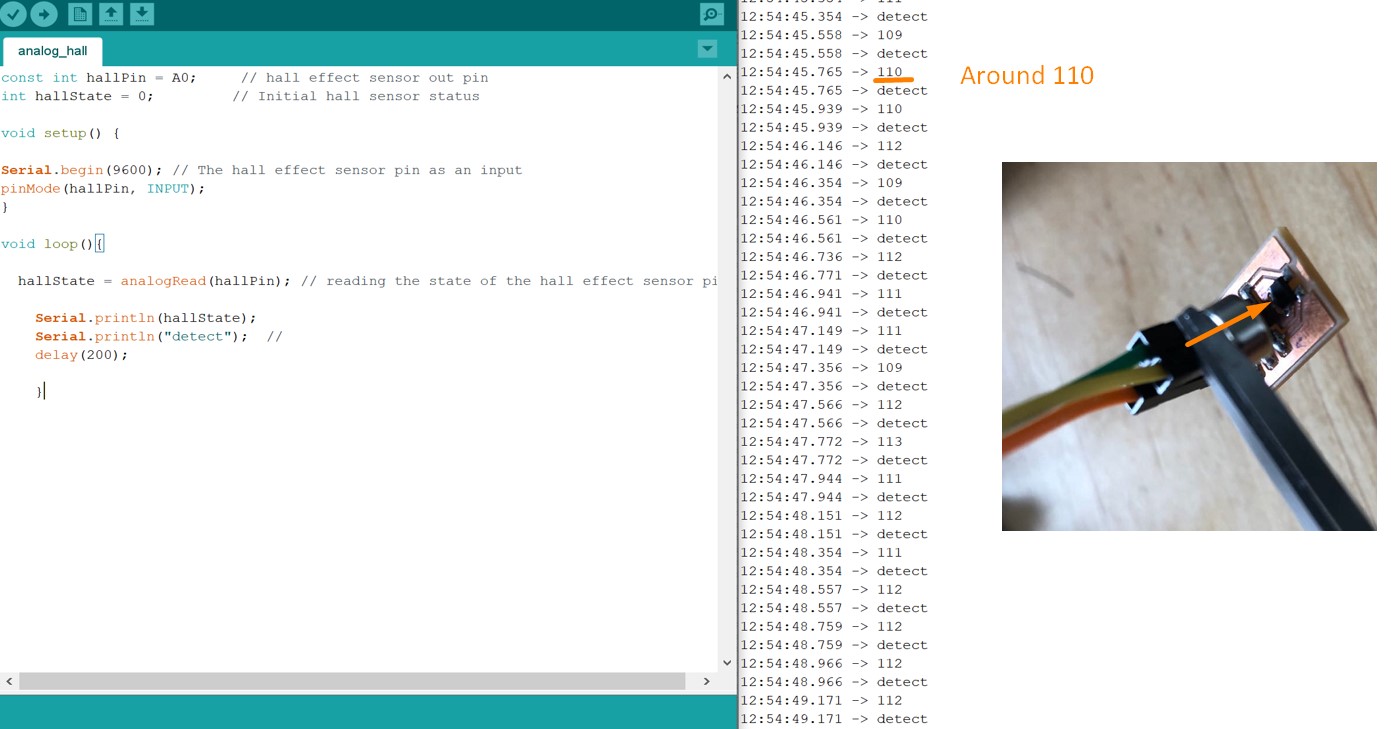
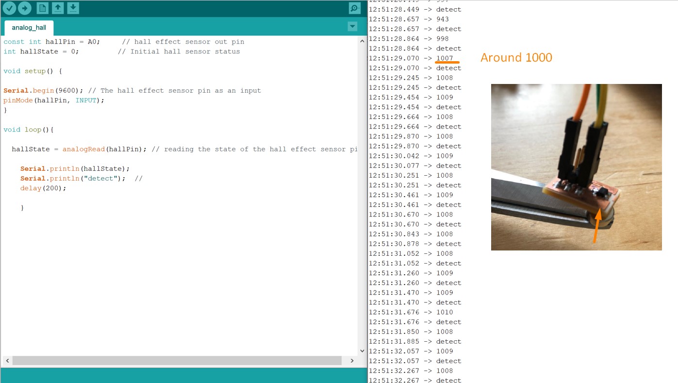
2.Analog Detection
In this case, instead of using the digital pin, the Analog pin A0 on the Arduino board is used. Moreover, the digitalRead() syntax should be changed to analogRead(). Our instructor Ari helped us to developed this analog detection method. In this case, instead of the binary stasus of "detected" vs " Not detected", the actual magnitude of magenetic field is detected and demonstrated.
The code used is as below:
const int hallPin = A0; // hall effect sensor out pin
The analog detection is reflected by the change of magnetic field magnitude and the voltage as the magnetic field approaches or moves away.
int hallState = 0; // Initial hall sensor status
void setup() {
Serial.begin(9600); // The hall effect sensor pin as an input
pinMode(hallPin, INPUT);
}
void loop(){
hallState = analogRead(hallPin); // reading the state of the hall effect sensor pin
Serial.println(hallState);
Serial.println("detect"); //
delay(200);
}
For example, when magnet moves towards the Hall effect sensor from the front, the detected magnetic field is around 110.
On the other hand, when the magnet approaches from the back, the detected magnetic field is around 1000.
We have also used the multimeter to detect the actual change of voltage when moving the magnet from different direction, which is shown in the following video.
Files
Arduino Code:
Individual: ● Hall Effect Sensor Test ● Full Motor Control Code
Group: ● Analog Detection ● Digital Detection