Applications and Implications Q & A
In this section, the answers to the following questions regarding my Final Project are explored and synthesized:
I have ideated two versions of the modern Weasley's Clock, a clock that shows the current location of each family member instead of time.
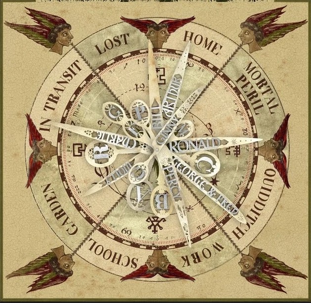
● What will it do?
This clock will show the locations of family members instead of the time, which is expected to be achieved by reading the location information from mobile devices. This clock is expected to provide emotional support among family members and create the sense of connections.
Two locations of this clock are designed with special functions: Emergent and Neptune.
● When the mobile devices sends out "Emergent" status, the clock should also show corresponding response. While the details are not decided yet, the clock is expected to push the emergent information to other members.
●Neptune is a category of locations that are relax, casual, and joyful other than home. Users should be able to manually label locations as "Neptune places". When they are in these places, the other members will know that they are safe and enjoying their time without being too intrusive to their personal spaces.
● Who's done what beforehand?
The original idea was from Harry Potter. Derived from this idea, several tutorials have shown how to create a modern version of this clock. In general, all tutorials are based on Wi-Fi communication between the phone and the clock, which the underlying mechanisms differed in details.
- Build Your Own "Weasley" Location Clock! (Raspberry Pi/ GWS Servos)
- A simpler Version (Arduino MKR1000/ Sail Winch Servo)
- LED Version(Partico Photon/LED)
● What will you design?
In this project, the majority parts will be designed and made within the lab.
- 2D Design: Clock face (laser cut)
- 3D Design: Clock structure, Clock hand/clock axis (3D Printing)
- PCB board Design: Communication board + Microcontroller board
- Algorithm Design: Code for (1) Wi-Fi communication, (2) Serial Communication, and (3) Output controlling
● What materials and components will be used?
- 2D Design: 4mm Plywood
- 3D Design: Black PLA material
- Electronic Design:
-Input: ESP8266 Wi-Fi Module (Type: esp-12f)
-Communication: ESP8266 + necessarry electronics componens
-Microcontroller: ATTiny1614 + MOSFET transistor for motor controlling + hall effect sensor + necessarry electronics
-Output Device: Servo Motor/Stepper Motor/LED
● Where will the materials come from?
Most of the components can be found in our local FabLab. I may need to buy motor and gears, or LEDs from online sellers.
P.S I tried to purchase a Sail Winch Servo that can be positioned at any angles within 720° online, but it never arrives. So I used a Stepper Motor from our lab instead.
● How much will they cost?
The cost is estimated based on Fab Lab Oulu Inventory, which should be estimately 71.09 € excluding electricity and other cost due to machine operations.
| Components | Function | Quantity | Source | Unit price | Total cost | ||
|---|---|---|---|---|---|---|---|
| Clock Body | |||||||
| 4mm Birch plywood | Clock face | 3 Sheets | Fab Lab Inventory | 369.51 | ~30 | ||
| 3D printer ABS filament | Clock hand, Axis | Fab Lab Inventory | 49.9 | ~10 | |||
| ESP8266 Board | |||||||
| ESP8266 Wi-Fi Module 12-f |
Wi-Fi Module for network communication | 1 | Fab Lab Inventory | 13.98 | 13.98 | ||
| Regulator ZLDO 3.3V 1A SOT223-3 |
Regulating the Voltage on ESP8266 | 1 | Fab Lab Inventory | 0.34 | 0.34 | ||
| Slide Switch SWITCH SLIDE SPDT 300MA 6V |
ESP8266 Control | 1 | Fab Lab Inventory | 0.57 | 0.57 | ||
| Button Switch SWITCH TACT SMD W-GND 160GF | ESP8266 Control | 1 | Fab Lab Inventory | 0.84 | 0.84 | ||
| Resistor 10KΩ |
3 | Fab Lab Inventory | 0.01 | 0.03 | |||
| Capacitor 1uF |
1 | Fab Lab Inventory | 0.07 | 0.07 | |||
| Capacitor 10uF |
1 | Fab Lab Inventory | 0.18 | 0.18 | |||
| 6-pin connector SMT RT Angle Male Header 0.1" (36pos) |
For serial Communication | 1/6 (6 pos) |
Fab Lab Inventory | 3.30 | 0.55 | ||
| ATtiny 1614 Board | |||||||
| ATTiny 1614 | Microcontroller for multiple tasks | 1 | Fab Lab Inventory | 0.67 | 0.67 | ||
| Transistor MOSFET N-CH SSOT3 |
Stepper Motor controller | 4 | Fab Lab Inventory | 0.26 | 1.04 | ||
| Regulator ZLDO 5V 1A SOT223-3 |
Regulating the Voltage on ATtiny1614 | 1 | Fab Lab Inventory | 0.45 | 0.45 | ||
| Capacitor 1uF |
1 | Fab Lab Inventory | 0.07 | 0.07 | |||
| Capacitor 10uF |
1 | Fab Lab Inventory | 0.18 | 0.18 | |||
| UPDI Connector CONN HDR 3POS 0.1 TIN SMD |
Connect to Programmer | 1 | Fab Lab Inventory | 0.65 | 0.65 | ||
| 2x3 Connector 6 Pos Header Connector 0.100"Surface Mount |
Connect to Motor | 1 | Fab Lab Inventory | 0.60 | 0.60 | ||
| 2x3 Connector 4 Pos Header Connector 0.100"Surface Mount |
Power, Sensor, and Serial Communication | 4 | Fab Lab Inventory | 0.66 | 2.64 | ||
| Motor | |||||||
| Unipolar Stepper Motor Jameco 2138812 |
Defining zero point | 1 | Fab Lab Inventory | 7.49 | 7.49 | ||
| Hall Effect Sensor SOT23W |
Set Motor Zero Point | 1 | Fab Lab Inventory | 0.45 | 0.45 | ||
| MAGNET 1-4"DIA | Set Motor Zero Point | 1 | Fab Lab Inventory | 0.29 | 0.29 | ||
| Total Cost: 71.09 | |||||||
● What parts and systems will be made?
In brief, the entire project can be divided into four major sections
-3D Design: Model the clock structure
-2D Design: Determine the content that will be demonstrated on the clock
-Communication Design: Determine the communication mechanism from the phone to the output part of the clock
-Electronic Design: Design the circuits and PCB board milling files
On the one hand, 2D and 3D designs will be done successively. The 3D design will be first in Fusion 360, and the contour of the design will be exported as PDFs, based on which the 2D design will be done.
On the other hand, the communication mechanism will be first determined, and in the electronic design stage, the required components will be integrated into PCB boards.
The communication mechanism is not fully developed at this stage, but the underlying logic has been clear:
1. The phone will track the GPS location
2. The location will trigger a preset event in IF This Then That(IFTTT)
3. The trigger event will send signals to ESP8266 via Wi-Fi
4. ESP8266 sends the signal to the microcontroller
5. Microcontroller control the motor to turn to specific positions on the clock
The specific connection mechanisms between ESP8266 and Microcontroller are not determined at this stage.
● What processes will be used?
At least these processes will be used for this project:
- 2D Design: Laser Cutting
- 3D Design: 3D printing
- Communication Design: Serial Communication, Networking and Communication
- Electronic Design: Circuit Design, Tool Path Generating, PCB Millng, Soldering
More details will be added as this project proceeds.
● What questions need to be answered?
- What locations should be included on the clock face?
- What is the best way to make each clock hand move according to the received signals?
- How to make the electronic system required for this project, when I have no relevant knowledge?
● How will it be evaluated?
- The clock can receive the location signal from the mobile phone
- The clock can demonstrate the location according to the signal received
- It will be nice if the clock can alarm the other members when some members are in Emergency status
- It will be nice if the mobile APP support this clock is able to calculate the time each members spend at home and at Neptune places and push notice to each member about their life balances.