Group Assignment
The group assignment of week 5 focuses on testing the design rules for our 3D printers. Please check our Group Assignment Page for more details.
Reflection for Group Assignment
1. Understanding the capabilities, strengths, and weakness of each 3D printer is important for choosing the right printer for a project
* When we print the same testing model from three different printers, we have learned how well each machine can process the design details such as the precision of sharp edges, the minimum wall thickness, rounded print, complex shapes, minimum hole sizes, minumum distance, and so on. This allows us to better design our individual design.
* For example, when design objects with thin gaps, the minimum distance should not be less than 0.4 mm because some machines cannot process gaps thinner than this number.
* For projects that will take long time, Stratasys Fortus 380mc and Sindoh 3DWOX DP200 will be good choices, because the former can run overnight and the latter allows users to resume previous projects.
2. The style of a printer in processing complex structures and supporting material is very important.
3. It is highly recommended to make customization in the printing software to reduce the usage of supporting materials.
Individual Assignment
The individual assignment of this week consists of three major parts: 3D design, 3D printing, and 3D scanning.
For 3D design and printing, I need an object that is only able to be created with additive manufacturing and impossible to achieve with subtractive manufacturing. In other words, this object should have a relatively complex internal structure, so simply cutting pieces away from a block of material will not work. 3D scanning can be either quite easy or exhausting, which depends on the scanning devices that one selects. The goal of this task is to build a 3D model from the scanner and refine it until it is readily printable.
3D Design
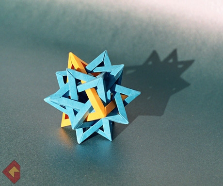
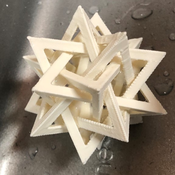
For this week's assignment, I decided to design and print a Five-Intersecting Tetrahedra , which consists of five right tetrahedra that are tangled with each other. The complex internal structure and irregular hollows of this object make it impossible to be made subtractively. Similar to my strategy during the computer-controlled cutting week, I decide to make this object because its complex structure can be made with multiple basic geometric objects.
My original idea was to create the individual tetrahedron in Fusion 360and combine them together by rotating them in proper angles. However, this strategy requires very complicated mathematical calculation so I ended up using a totally different strategy with blender.
Fusion 360 Approach
I first tried to follow a parametric design strategy with Fusion 360. A right tetrahedron is composed by four equilateral triangles. So my initial plan was to make one right tetrahedron and create four copies of it. By rotating and tilting these tetrahedra, I should be able to create the object I want. This strategy is only partially feasible. The idea was not wrong. However, the problem is that creating tetrahedron in Fusion 360 is very easy, while making the tetrahedra intersect with each other properly is extremely hard.
There is a shortcut for creating a tetrahedron in Fusion 360: which uses the Extrude Function. I gained this inspiration from this video: How to draw a Tetrahedron in Fusion 360.
There is only two steps required for creating a tetrahedron:
1. Create an equilateral triangle base
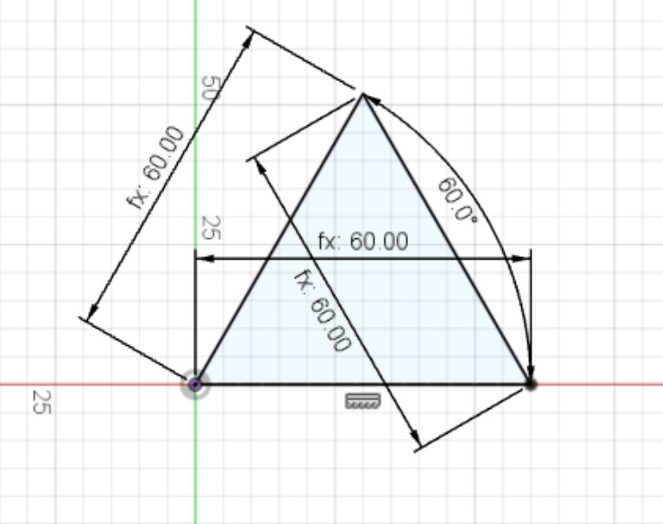
2. Apply the Extrude trick
Select the base and adopt the following settings:
Create >> Extrude >> Distance: 100 mm >> Taper Angle: -19.471°
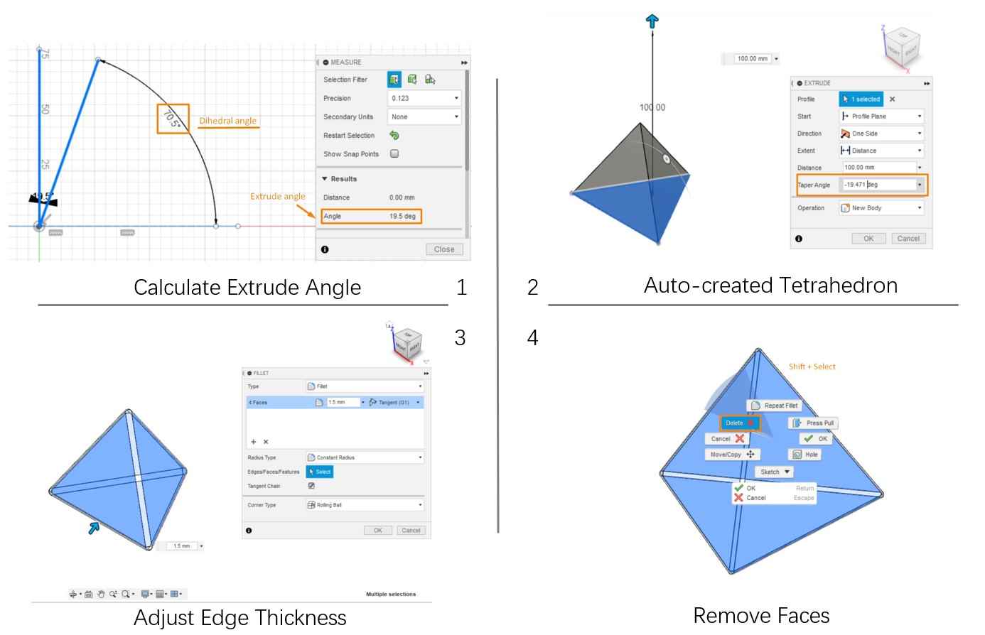
There are two critical part of this trick: (1) set the Taper Angle as the complementary angle of tetrahedron's dihedral angle and (2) set the Distance as any number that is larger than the height of the tetrahedron.
                    dihedral angle of tetrahedron: arccos(1/3) ≈ 70.529 °

                    Taper Angle = dihedral angle - 90 ° ≈ -19.471°

                    Tetrahedron= edge*sqrt(6)/3
After adjusting the edge thickness with Fillet setting and removing the four faces, a tetrahedron is ready to be assembled.
However, the calculation for the rest of steps are extremely complex, which requires the coordination of all twenty tips of the tetrahedron to be precisely calculated and converted into 3D distance. Other the other hand, such operation is not sufficiently supported in Fusion 360. It is very hard to have a holistic view of the object while adjusting the location. Thus, I shifted to another approach.
Blender Approach
The blender approach of creating the five-intersecting tetrahedra is not parametrical but relies on the unique build-in functions in this software. I learned this method from this tutorial Orderly Tangle - Tetrahedron Star Polylink, which mainly bases on the transformations of an ico sphere.
The Compound of Five Tetrahedron can be created with the following steps:
1.Unit Setting
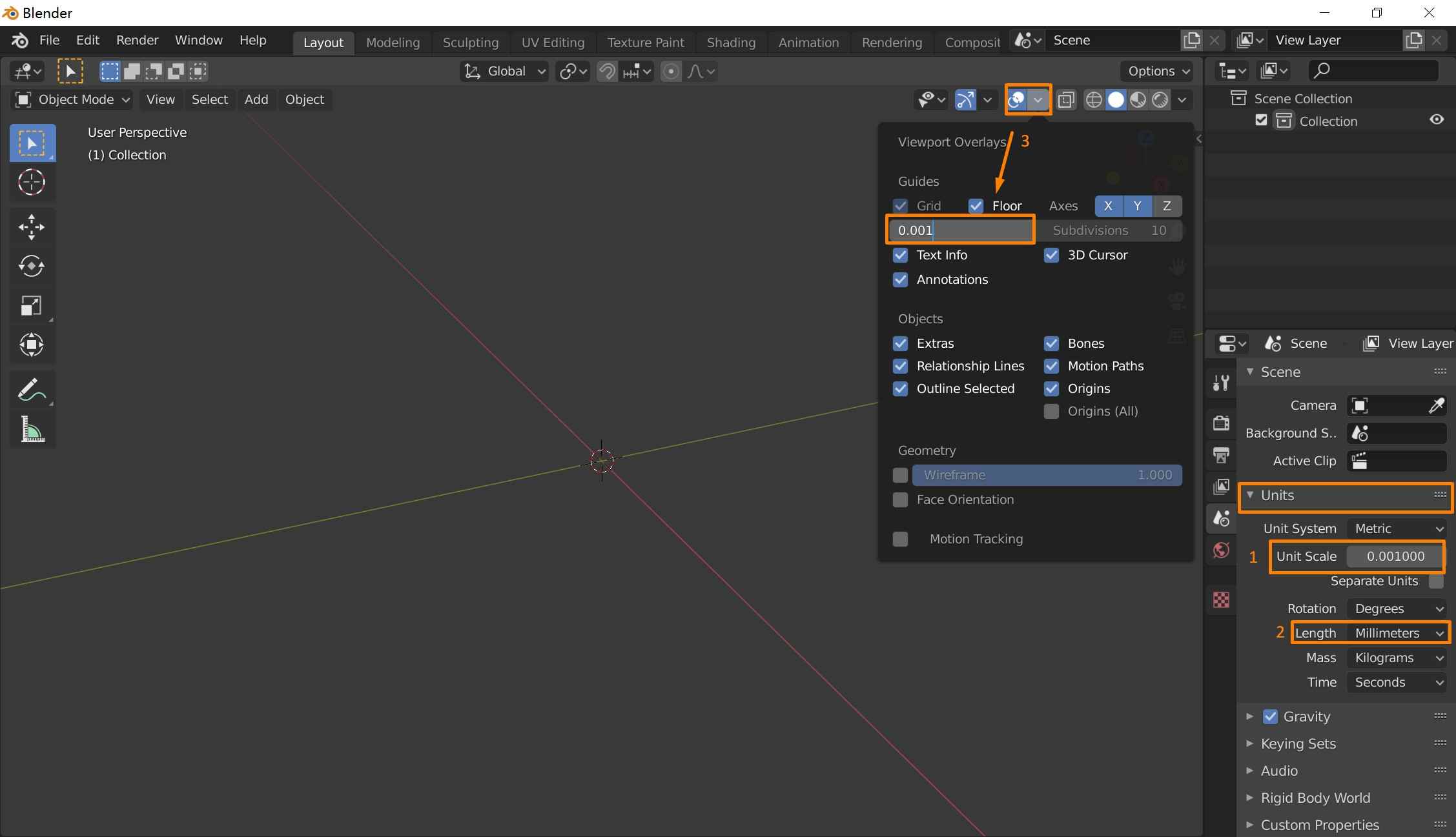
In the right docker, change the setting of units to:
Unit Scale -> 0.001
Length -> millimeters
ViewPoint Overlays -> 0.001
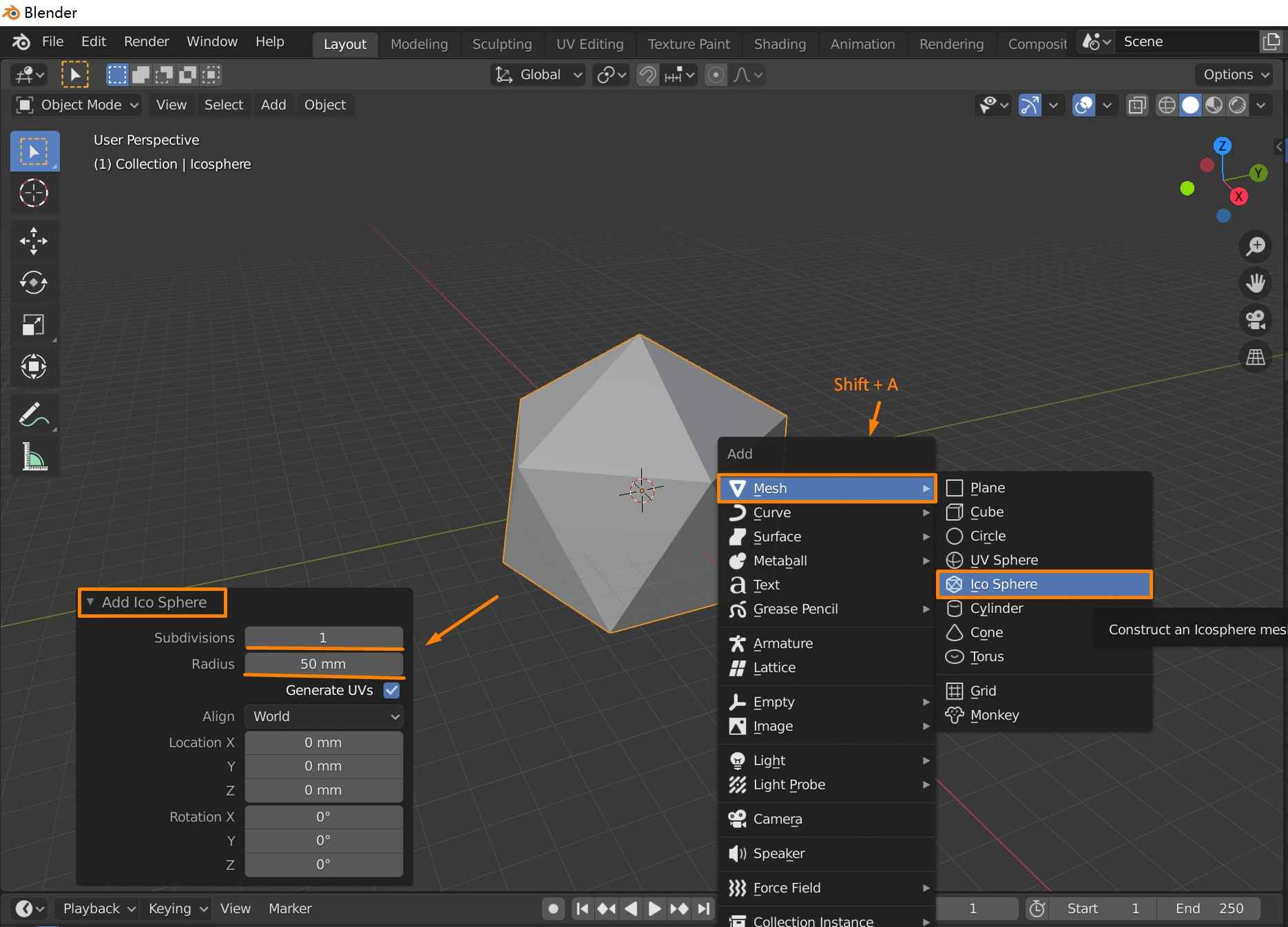
2. Create Ico Sphere
Open new file >>Shift + A (Add Menu) >> Mesh>> Ico Sphere
When adding the ico sphere, a docker will appear on the left lower corner of the interface, open the menu and adopt the following setting:
Add Ico Sphere >> Subdivisions-> 1 >> Radius -> 50 mm
The radius depends on individual's design, I used 50 mm here for convenience.
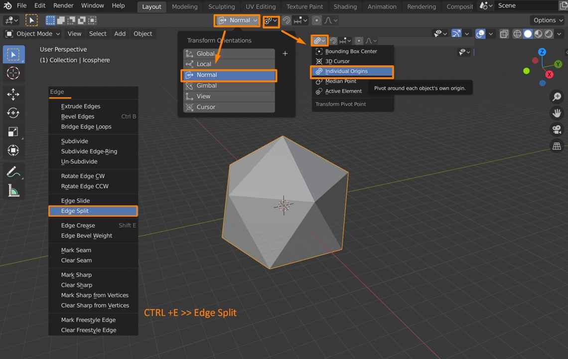
3. Edge Split
The next step is to split the face of this icosahedron. Keep the icosahedron selected and follow these procedures:
Tap (Select Mode) >> CTRL+E (Edge Menu) >> Edge Split
At the same time, two parameters on the top tool bar need to be changed:
Transform Orientations -> Normal >> Transform Pivot Point ->Individual Origins
Each face of the icosahedron has now been detached from each other. To test if the split is successful, press 3to select individual face. Pressing G while using cursor to drag a face of the ico sphere to test if each face can be modified separately.
4. Create Compound Five Tetrahedra
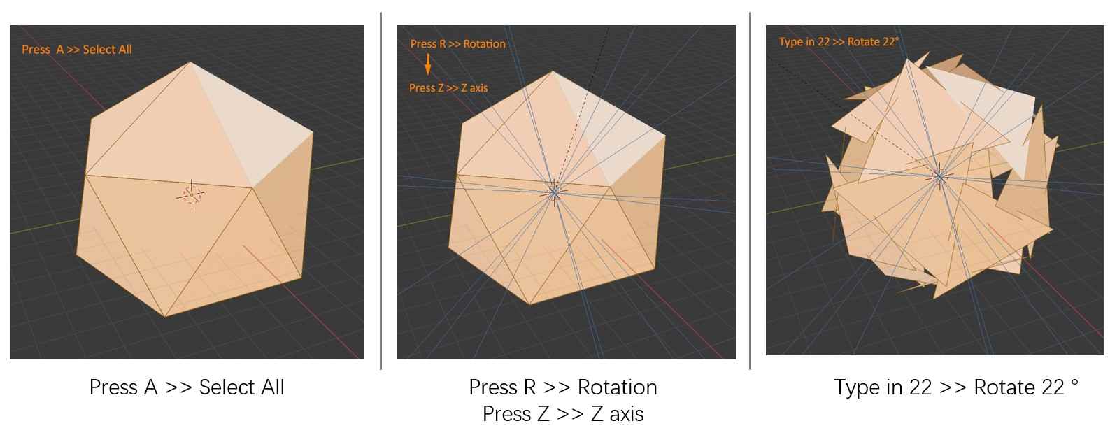
a. Rotation
Press A (select all) >> Press R (Rotate) >> Press Z (Axis Z) >> Type "22" (rotate by 22°)
b. Adjust Faces Offset
Press Alt + S to evoke the Shrink Flattern Tool and set the appropriate offset parameter or manually adjust the faces until it shows the shape of the Five-Intersecting Tetrahedra. I used 29 mm in this case.
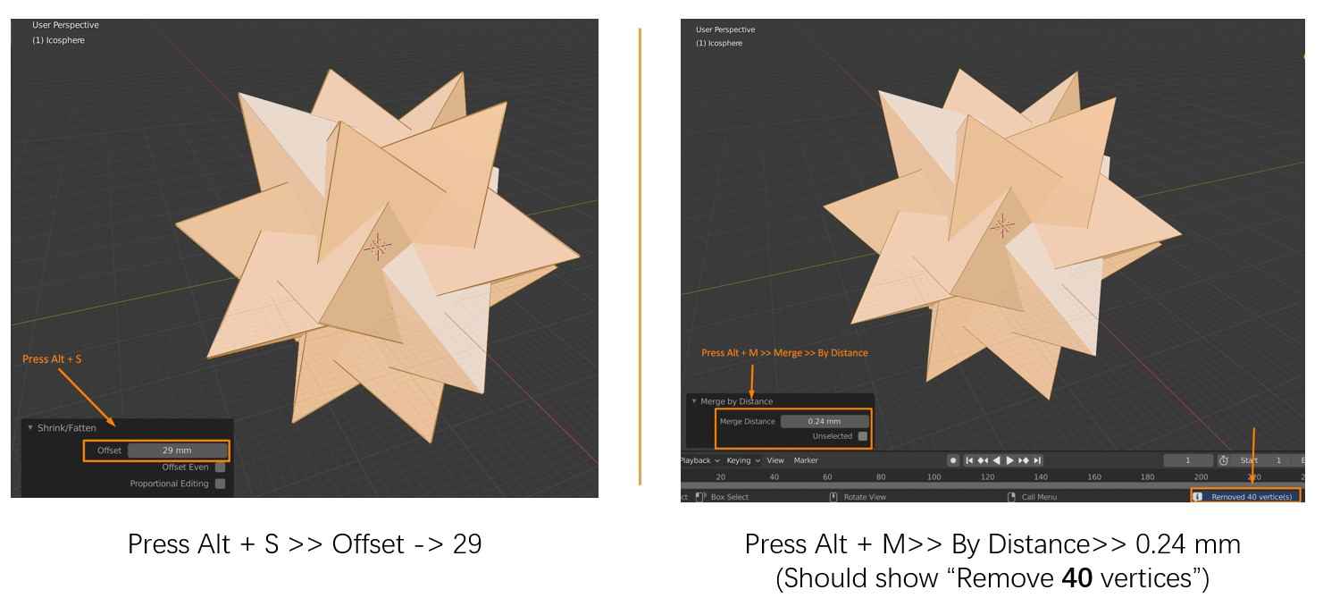
c. Weld Corner Points
Press Alt+ M (Merge Menu) >> By Distance and set the appropriate Merge Distance. A notice that says "Removed 40 Vertice(s)" will pop up, which indicates the proper distance has been met and the corners are welded. In this case, the proper distance for my model should be at least 0.24 mm.
d. Inset Setting
Press I twice (Individual Inset tool) >> Thickness and set the appropriate thickness of the edge. I set the thickness to 3.5 mm for this model.
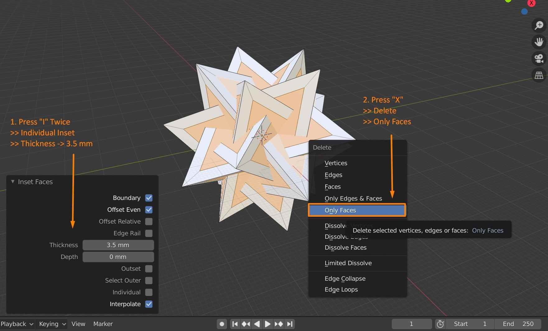
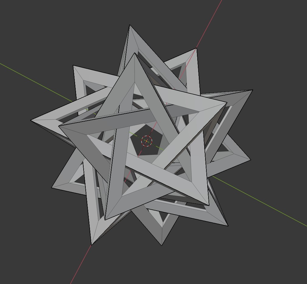
e. Remove Faces
Press X (Delete selection) >> Faces and the Five-Intersecting Tetrahedra model is constructured.
5. Refine the Model
Some details of the model still need to be refined for 3D printing, especially the non-manifold components.
Press L ( Select linked vertices) of any one of the tetrahedron to select and Press Shift + H to hide the unselected tetrahedrons.
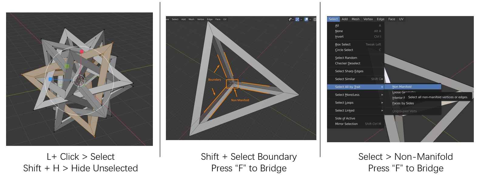
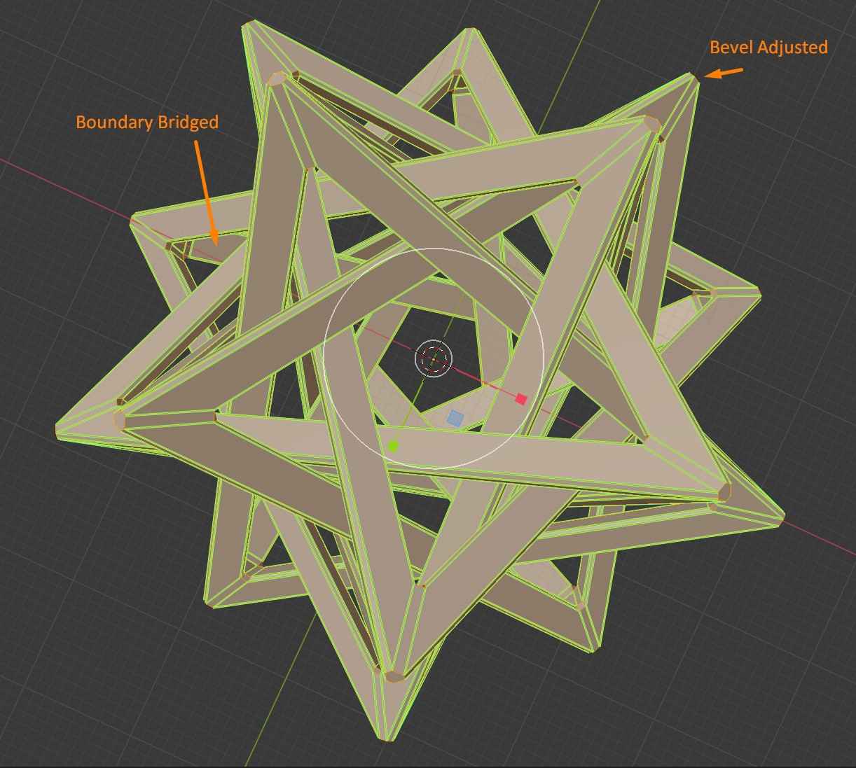
a. Bridge boundaries
As shown in the figure, the opposing boundaries of the edges need to be bridged.
Press Shift while selecting the boundaries >> Press F then a phase will be created to bridge the boundaries. Repeat the same procedure for all 6 edges.
b. Close Non Manifold Holes
To close the non manifold parts, Select >> Select All by Trait >>Non Manifold >> Press F and the parts will be bridged.
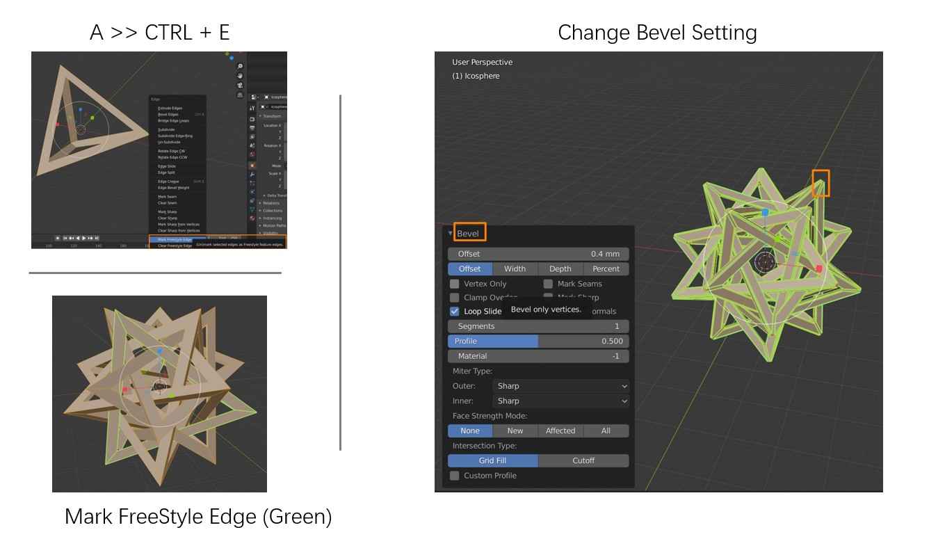
c. Mark the Edited Tetrahedron
Because each of the tetrahedra will be refined individually, the modified tetrahedron should be marked to avoid confusion.
Press A (select all) >> CTRL+E (Edge Menu) >> Mark Freestyle Edge
Then the edge of the modified tetrahedron is highlighted in green, which can distinguish it from other unprocessed tetrahedra. Press Alt +H to unhide all tetrahedra and repeat the same process for the rest of the tetrahedra.
When all the tetrahedra have been processed, the model is ready for 3D printing. CTRL + B can invoke the Bevel Menu. Adjusting the Bevel offset can make the tips of the object less sharp so it will be easier for printing.
From the group assignment, I have learned the capabilities of different types of 3D printers at Oulu FabLab. Thus, when I realize that my design will require massive supporting material that can be removed afterwards and will take a relatively long time, I know that Stratasys Fortus 380mc may be the best choice for this task.
Reflection for 3D Design
1. Fusion 360 is powerful in parametric modeling, but when the object itself is hard to create parametrically, blender may provide a strong support
3D Printing
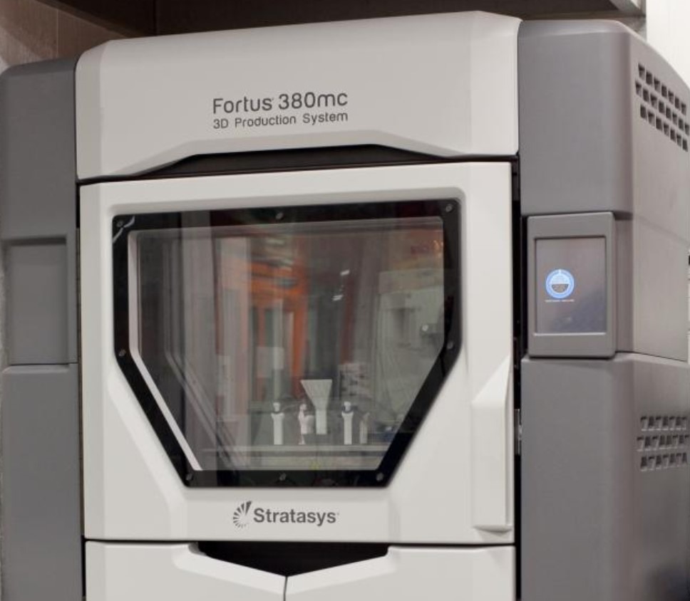
As mentioned above, considering the tetrahedron model has many hollows in the internal part, which will require many supporting materials, I choose to print with Stratasys Fortus 380mc. The Stratasys Fortus 380mc printer at Oulu FabLab can process the printed object and supporting material separately and can work without constant supervision overnight, which makes it the best choice for printing objects with complex internal structure. This machine uses ABS as printing material, which has a great performance in material strength, ductility, and thermal stability.
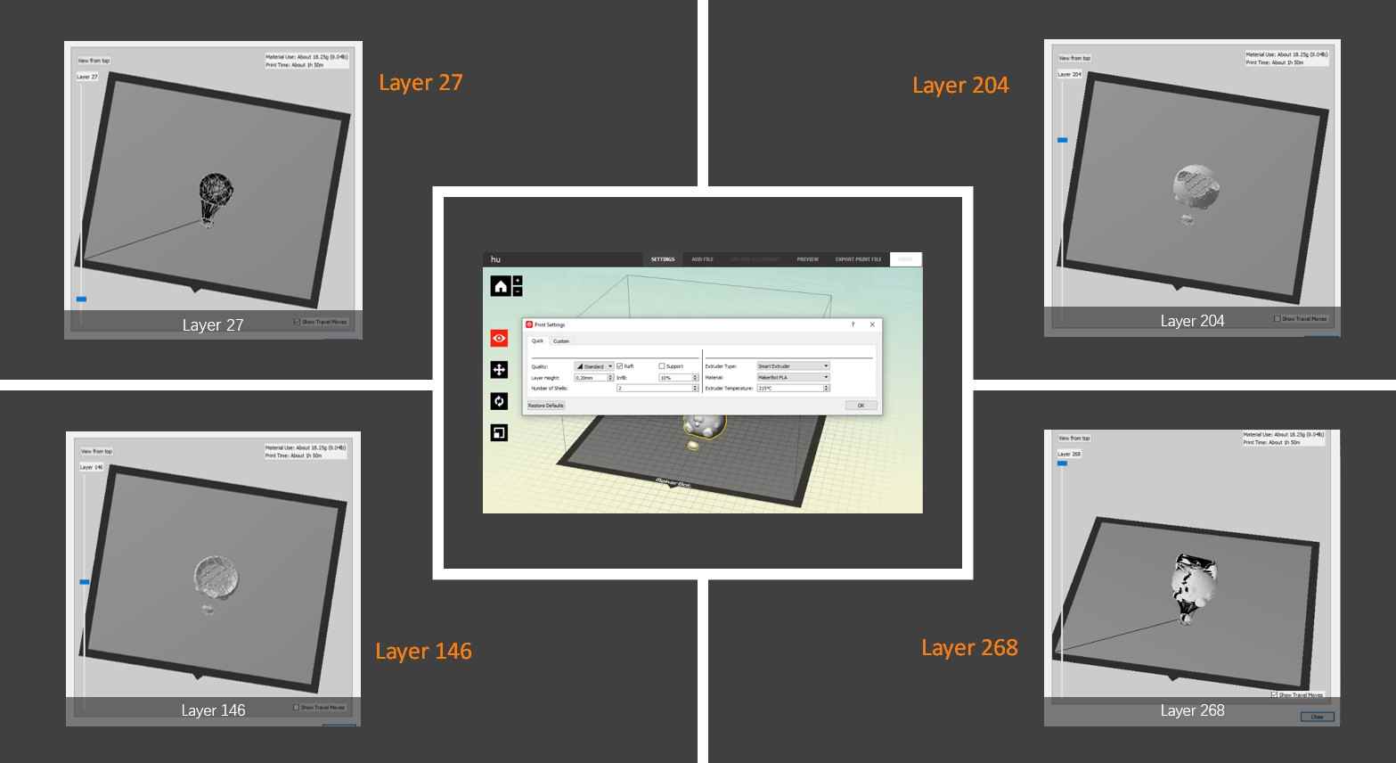
It only requires several simple steps to set the printing task and send to the printer.
1. Import the file into GrabCAD Print
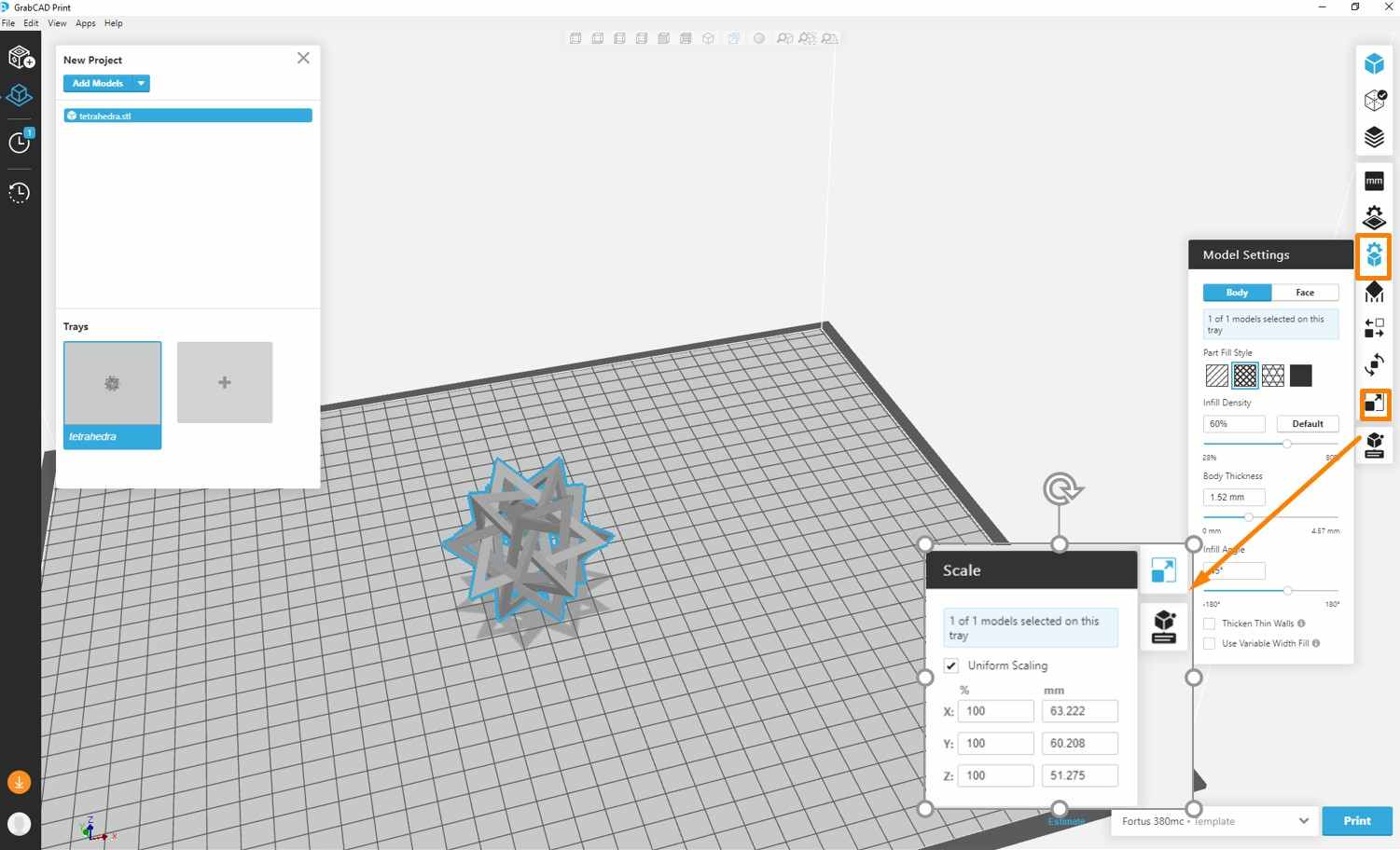
2. Adjust the model settings
Users can change multiple settings with GrabCAD Print, while the majority of them can retain the default values.
Model Settings and Scale may be the two most frequently modified sections.
-In the Model Settings section, users can modify the filling properties of both body and face, such as Part filling style, Infill Density, Body Thickness, and Infill Angle.
-In the scale section, users can adjust the model to appropriate printing size.
In my case, the model setting I used was:
Part Fill Style: Grid
Infill Density: 50%
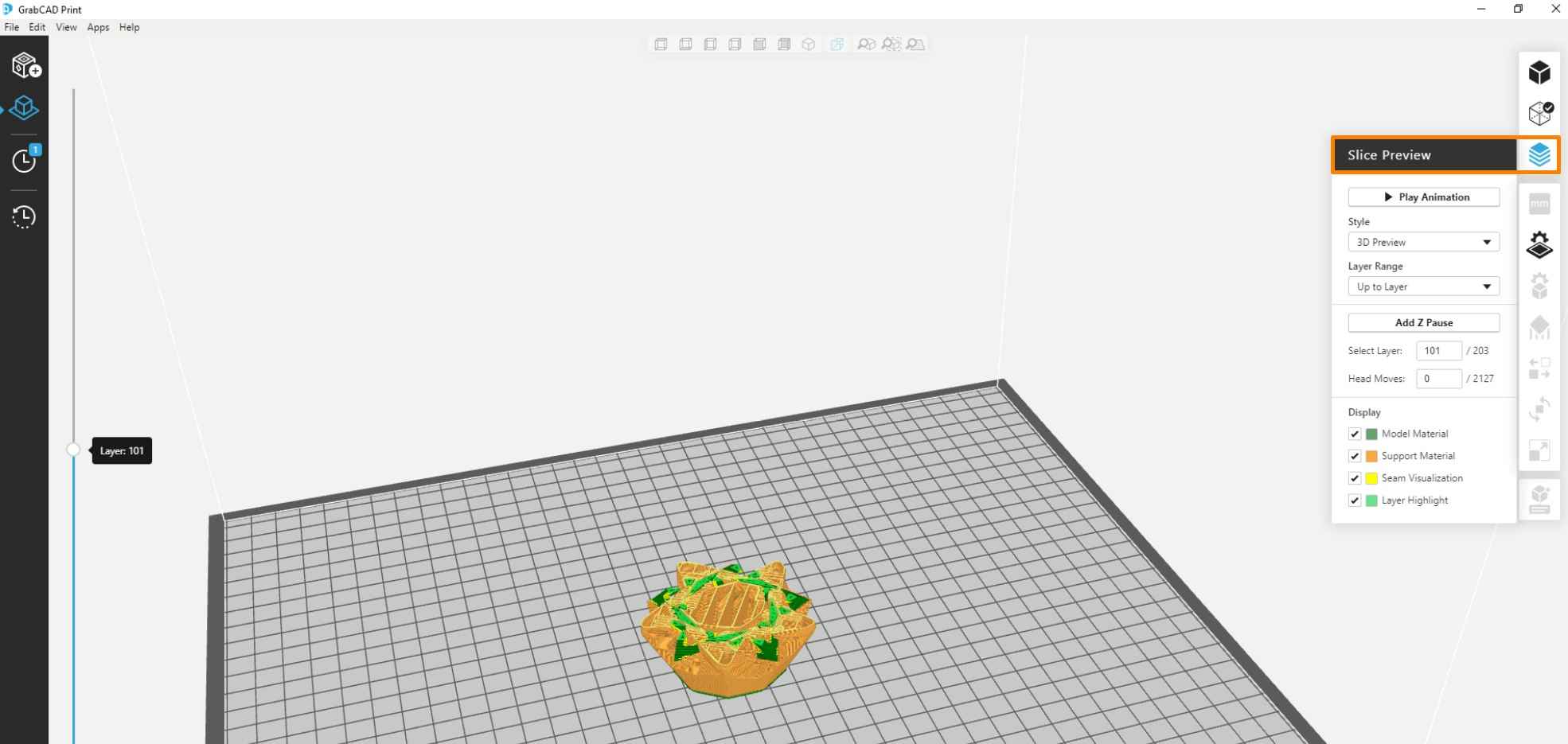
3. Slice the model
The next step is to slice the model. The software will automatically calculate the slicing result and the materials for support. The sliced model can be exported in cmb format.
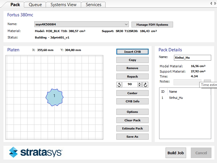
4. Control Center
Import the cmb file to the Control Center and then arrange the location of the model. At this stage, multiple cmb files can be set and print together. Using Repack function will allow the Part Placement to be automatically adjusted. Click Build Job will send the file(s) to the 3D printer.
These are the data for my 3D printing process:
● Model:
Material M30——BLK
Size:16.56 cm^3
● Support:
Material SR30
Size: 27.92 cm^3
● Required Time: 4:34
Tips:
Please remember to always copy the model files to the local computer and then import the files from local.
* If the models are directly sent to the printer from the memory sticks, it will have to stay connected until the printing process finishes. Otherwise, the printer will stop and pop out error messages.
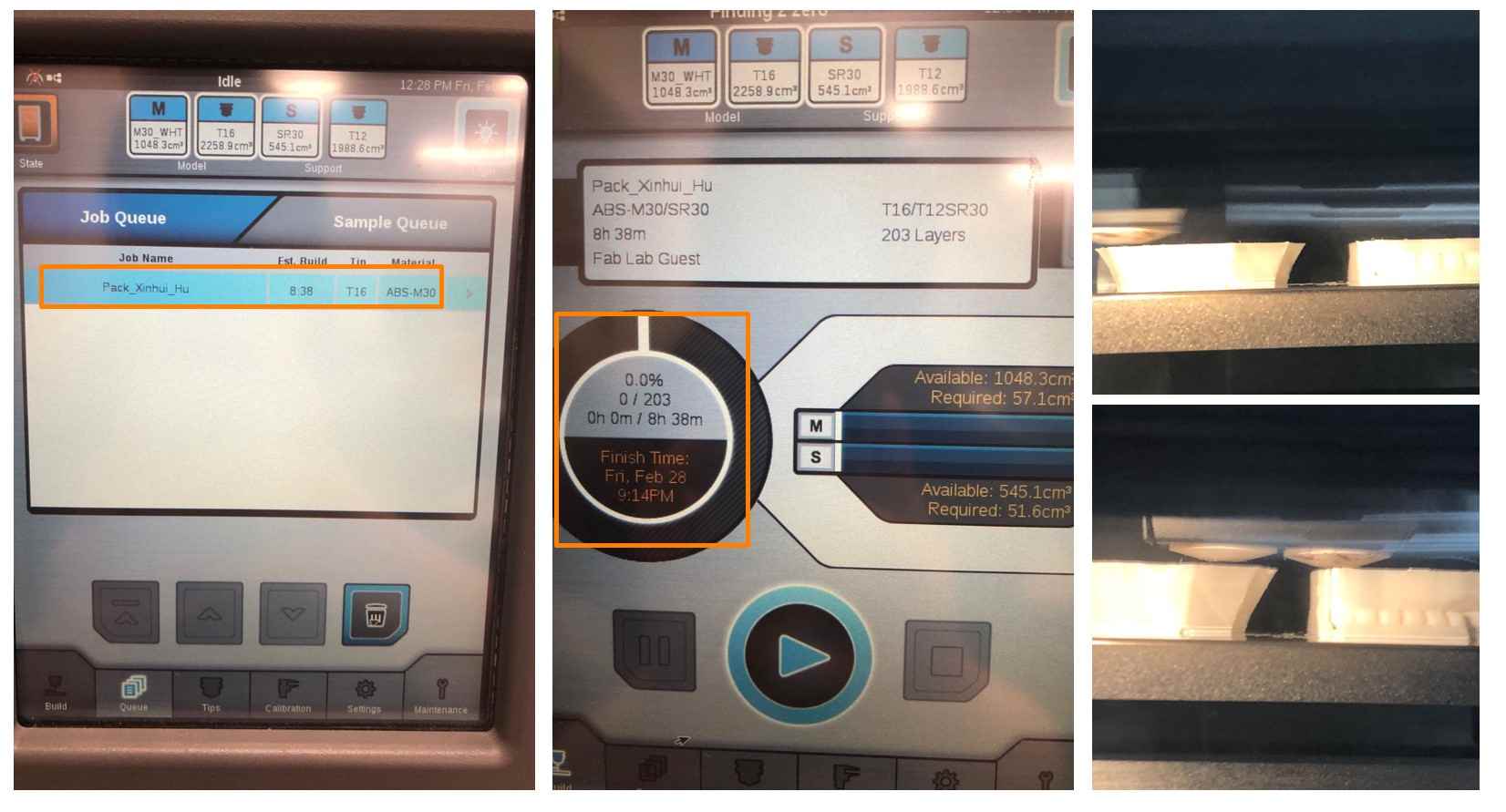
5. Printer Setting
After the models are sent to the printer, a base sheet should be placed into the printing chamber. Then, select the task from the Job Queue and press Print to start the printing process. The progress and remaining time will be shown on the panel board. Stratasys Fortus 380mc can run automation without supervision, so all I need by this time is to wait for the printing ends.
* If the user choose to print multiple objects in pack, all the objects will be printed together by layer instead of finishing one and then another.
6. Cleaning Support Material
When printing finished, carefully take the base sheet with gloves to prevent being injured by the heat. Detach the printed object from the base sheet and place it into the cleaning tank to remove the supporting material. It is important to make sure the printed objects are fully immersed into the Sodium Hydroxide (NaOH).
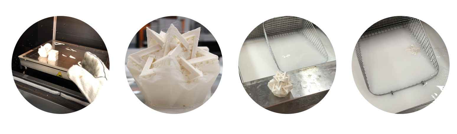
It takes several hours for the support material to be solved. Gloves must be put on when removing the printed objects from the cleaning tank.
Reflection for 3D Printing
1. The 3D Printing process is relatively smooth in my case, especially after we learned the capabilities and features of different 3D printers. Knowing their capabilities are important when selecting the right machine to use. For example, I know my object will take a lot of support material and a long time to finish, so I have chosen Stratasys Fortus 380mc printer. If I need to leave the lab and want to resume my work in the next morning, then Sindoh may actually be a better choice.
2. The printing chamber is hot! Do not forget the gloves!
3. Do not forget the gloves for putting your object in or removing from the cleaning tank!
3D Sacnning
I used MakerBot Digitizer for 3D scanning because of its easiness of use and stablity.
MakerBot Digitizer
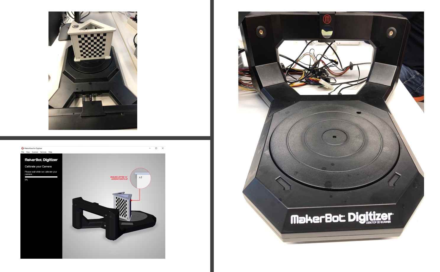
MakerBot Digitizer is a desktop scanner that can generate a 3D model of an object by automatically spinning the object at a slow pace while taking pictures of it. In this process, a beam of red light sheds on the scanned object, which allows the software to calculate the surface contour by the curves of the beam.
There are just several simple steps for creating 3D models with this device:
1. Calibration
The camera can be calibrated with a wooden object with a checkerboard pattern, which allows the camera to adjust the light condition in the room. In Oulu FabLab, the MakerBot Digitizer has been already well calibrated, so I skipped this step.
2. Preparation
Having a proper scanning environment is important.
The scanning background needs to be clean, otherwise, the items in the background will be recognized as a part of the object. Thus, in my case, the scanner faced the wall to avoid this problem.
The light condition is also crucial. It is best to have multiple light sources, especially when the surface of scanned object is smooth, because the reflection may not be well detected by the scanner.
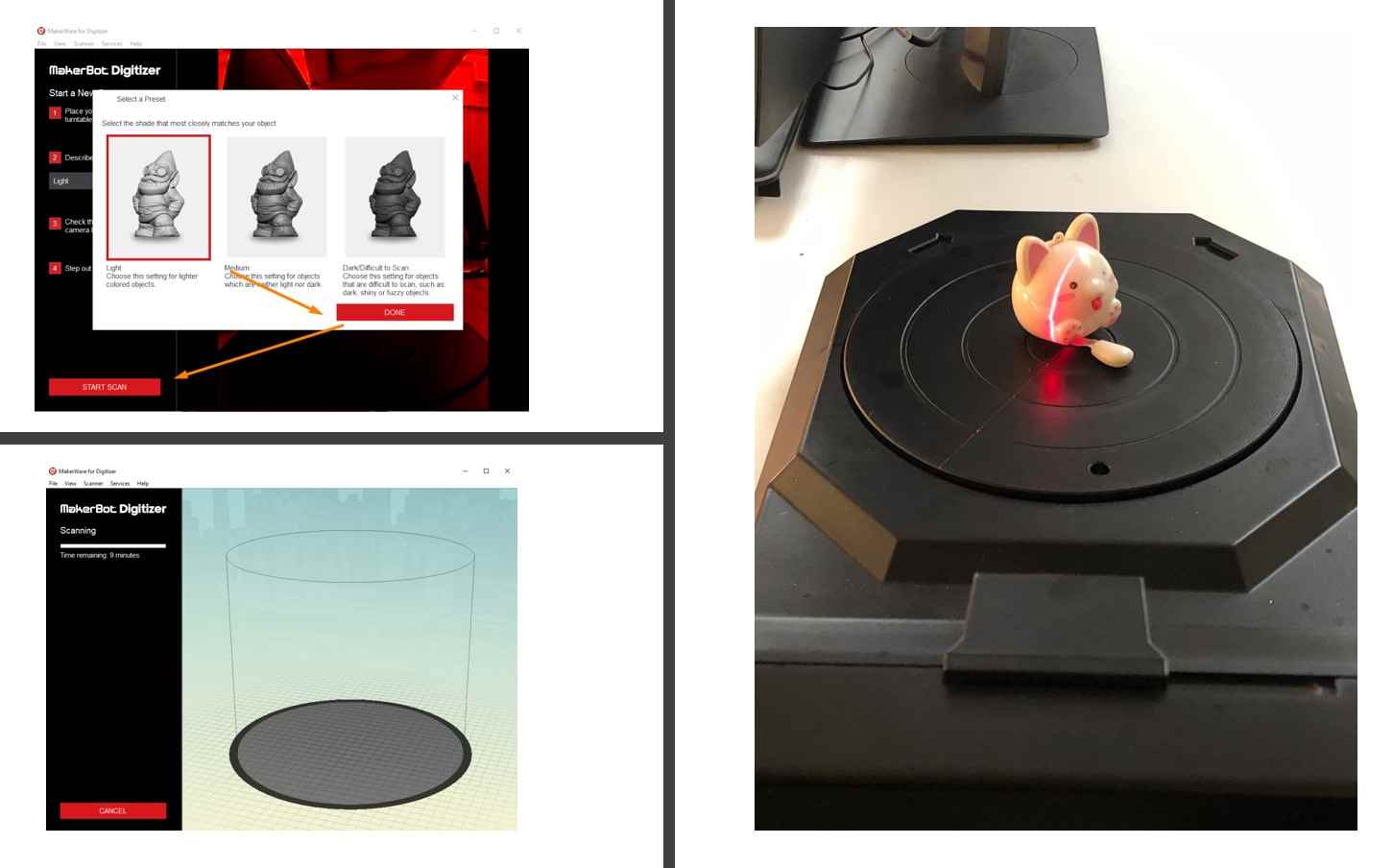
3. Scan
The scanning process will be operated by the MakerBot Digitizer software. The scanned object needs to be within a certain size limit. There are not many things that users need to change except the light condition. Users can choose from Bright, Medium, Dark and the scanner will automatically adjust the settings. Press Scan will initiate the scanning process, which normally takes around 9 minutes.
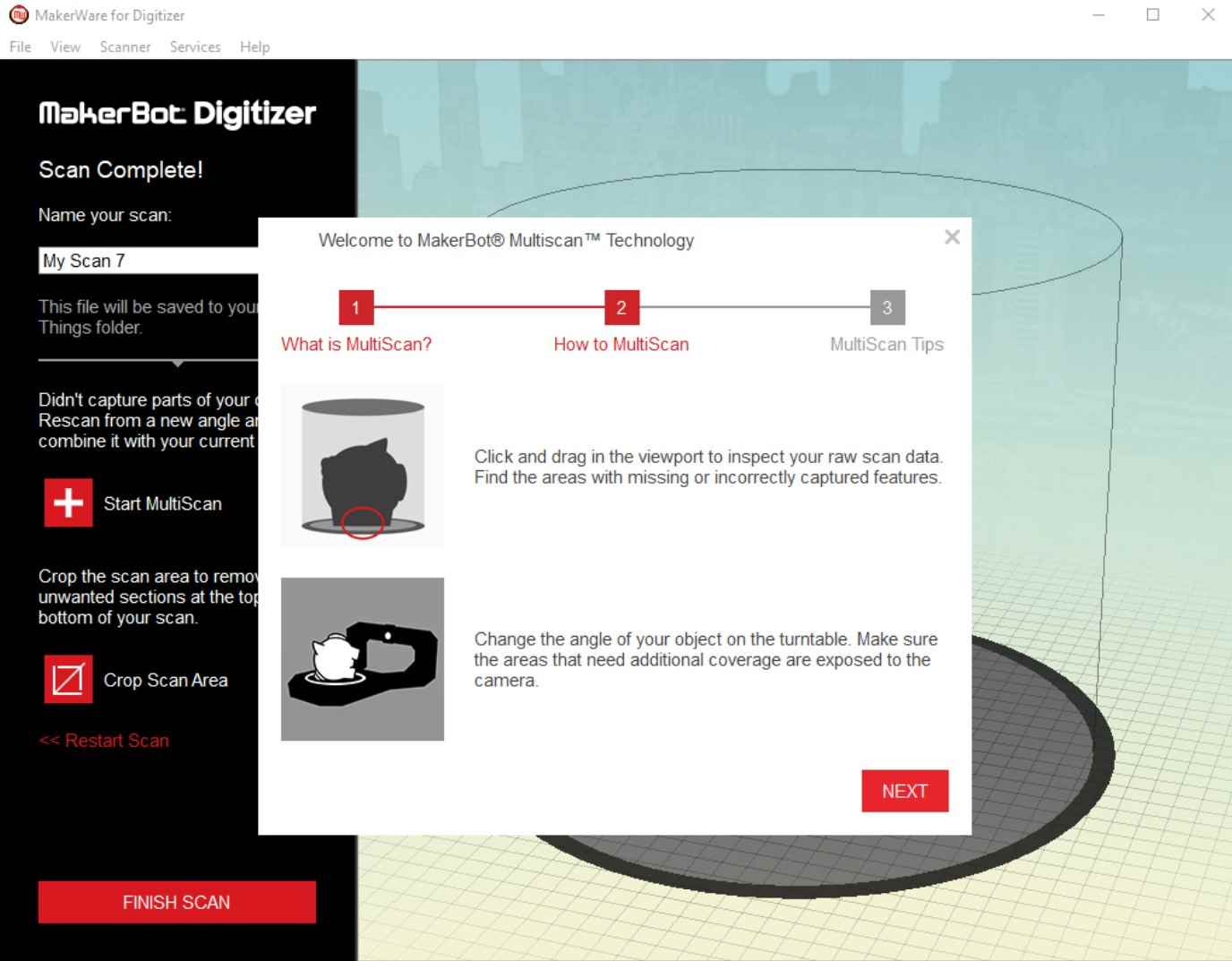
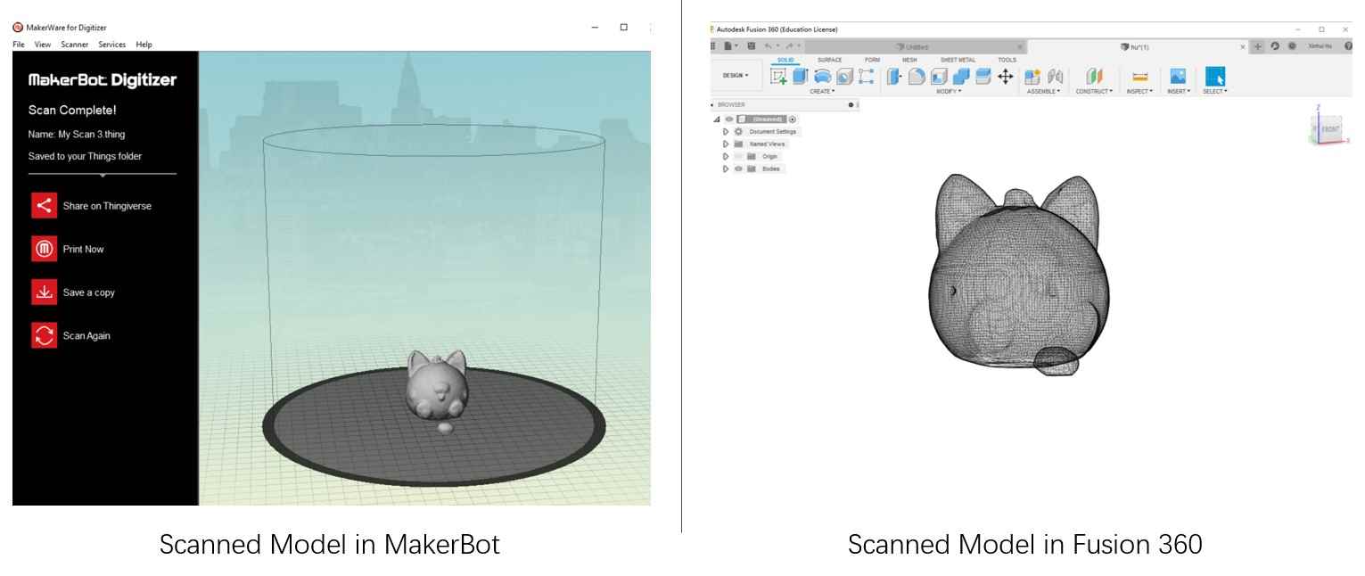
4. Modify
If the object has multiple sides, users can gain a holistic view of the object with Multiscan function, which will synthesize multiple scans of the object and generate the holistic model.
The MakerBot Digitizer allows users to modify the size, orientation, location, and view perspective after saving the scanned copy.
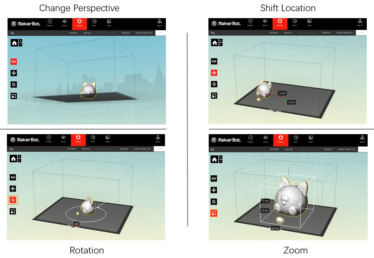
The MakerBot software also provides 3D Printing preview which allows the users to check if the model is ready for print.
For further and more complex modification, the obj format files can be exported from the MakerBot software and then be imported into other CAD software, like Fusion 360 or Blender. Since my scanned model has a reasonable quality and seems to be okay to be printed, I did not need to change much in the model.
Reflection for 3D Scanning
1. The environment, especially the light condition and background, are crucial to the scan quality.
2. If the surface of the scanned object is smooth, the reflection of light may not be recognizable for the machine
Files
3D Models Design:
● Five-Intersecting Tetrahedra.blend
● Five-Intersecting Tetrahedra. stl
3D Printing:
● Five-Intersecting Tetrahedra.cmb
3D Scanning:
● cat.makerbot
● cat.obj(compressed as RAR)