Group Assignment
The group assignment of this week focus on comparing the performance and development workflows for different architectures. Please check our Group Assignment Page for more details.
Individual Assignment
This week's individual assignment is about reading a microcontroller data sheet program the board to do something. ATtiny 1614 is the core component of my final project, whose datasheet helped me a lot in the process of accomplishing the project. Thus, I would like to discuss the datasheet of this chip and program it to do simple tasks.
Datasheet Interpretation
The ATting 1614 datasheet contains many breif and detailed information about what will this chip do and how to utilize it. I would like to focus on the contents that are essential to my project.
1. Series Overview
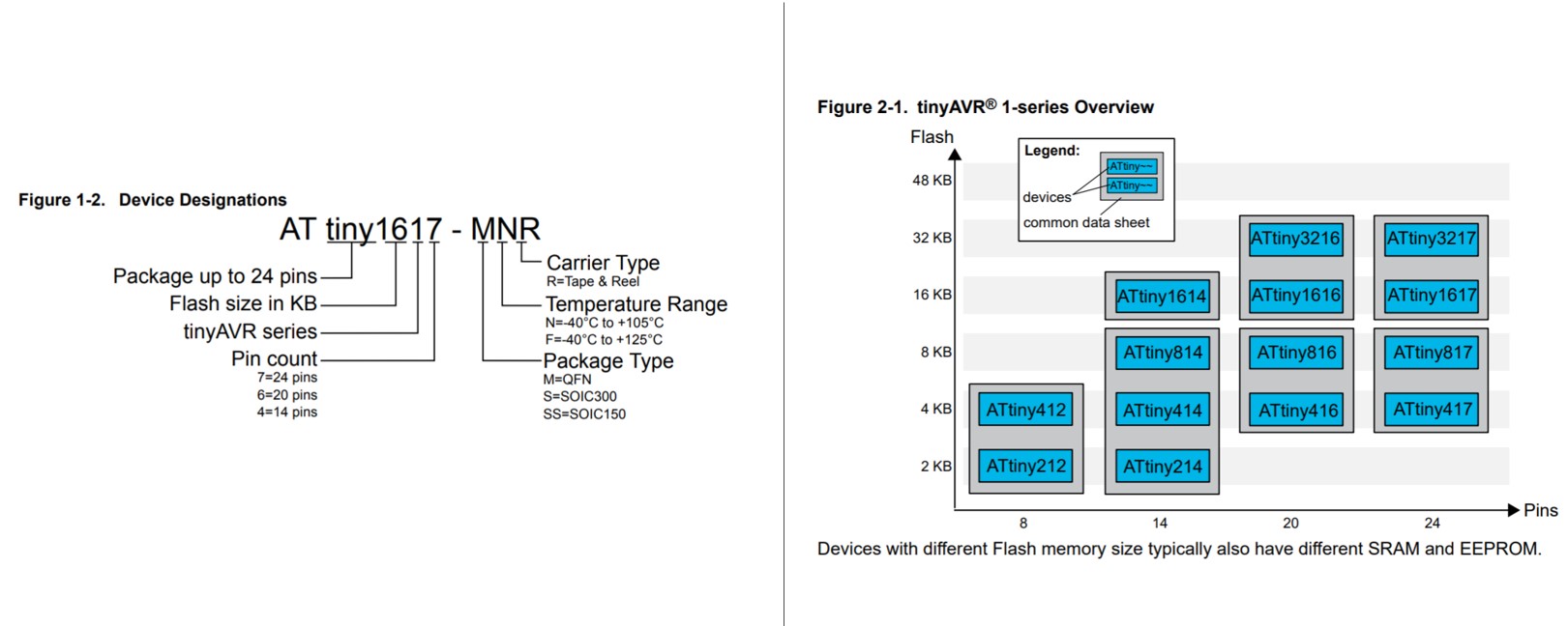
The series overview reveals knowledge about the ATtiny series. I personally found this section helpful, as I did not know how ATtiny 412, which I used weeks earlier, differ from ATtiny 1614 that I will use for the final project. With these diagrams, I was able to decode the information contains in the name and understand what alternative chips I can use if I do not have the exact same chip in the assets.
The series overview reveals knowledge about the ATtiny series. I personally found this section helpful, as I did not know how ATtiny 412, which I used weeks earlier, differ from ATtiny 1614 that I will use for the final project. With these diagrams, I was able to decode the information contains in the name and understand what alternative chips I can use if I do not have the exact same chip in the assets.
2. Pin Out
Pin out may be the most important information when reviewing the datasheet, as this determined how this chip should be connected to the other components and how to arrange the circuits.
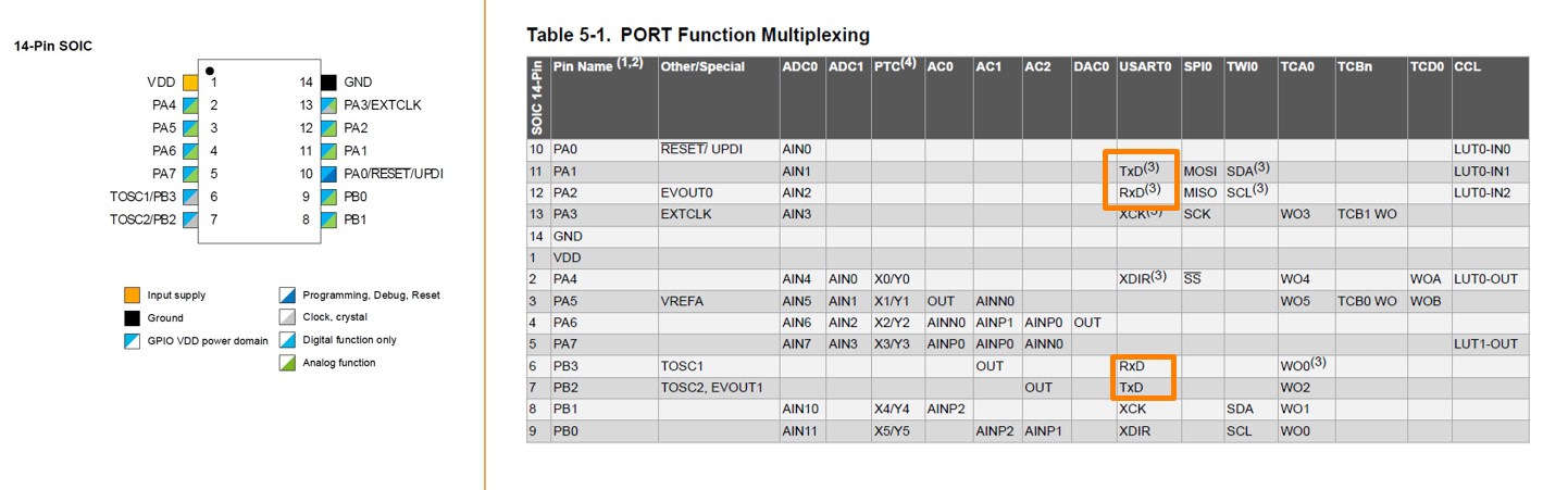
The color code indicates the function that each pin can achieve.
VDD: Power Supply
GND: Ground
Digital pins: PA0, PA1, PA2, PA3, PA4, PA5, PA6, PA7, PB0, PB1, PB2, PB3
Analog pins: PA1, PA2, PA3, PA4, PA5, PA6, PA7, PB0, PB1
UPDI Programming pin: PA0
The Port Function multiplexing table gives more details about what can the pins achieve.
Caution:
Due to the way that the pins are arranged, the backup RX(PA1) and backup TX (PA2) were demonstrated earlier than the actual RX(PB3) and TX(PB2), which makes it very easy to mistakenly use PA1 and PA2 as Rx and Tx.
Using Serial.swap(1); in the setup() section can activate the backup Rx/Tx if the wrong pins were chosen.
It will be also helpful to refer to pin out image that were not included in the datasheet
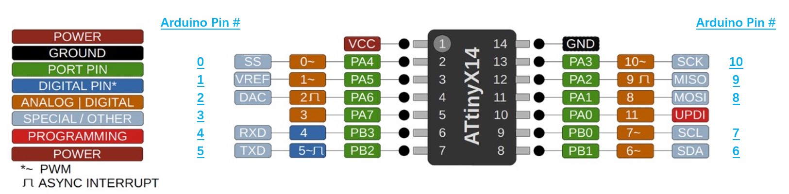
This pin out instruction not only have a clearer label of each pin but also include the pin numbers that will be used in the Arduino IDE.
With these information, I can determine the pins that I will use for the project. For example, in my project, I will need to use ATtiny 1614 to fulfill these functions:
● Being programmed with a FT232 Programmer using UPDI
● Being powered by external power supply
● Control 4 transistors that determines the movement of a unipolar stepper motor
● Control a LED bulb
● Receive signals from ESP8266 via serial communication
● Receive signals from a Hall Effect Sensor
Then, addressing these goals, these pins will be used for each function have been used in my project :
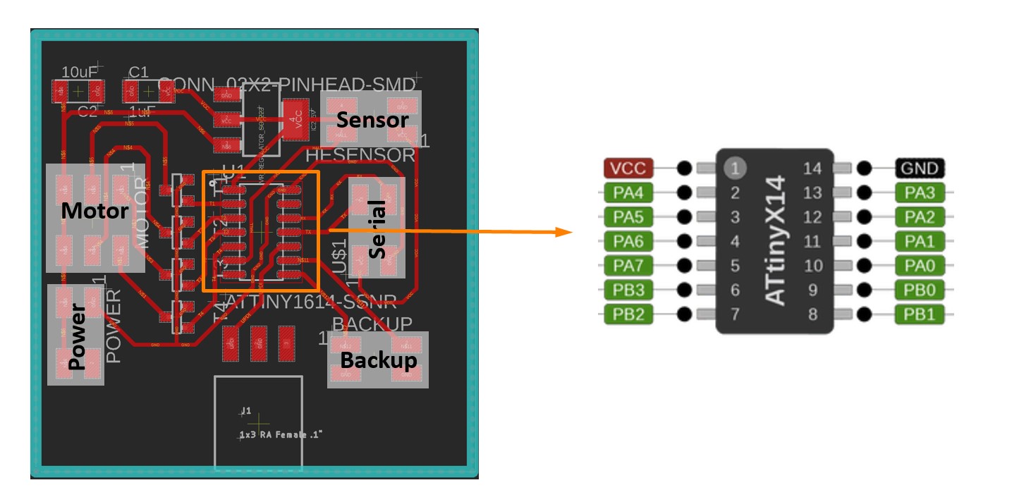
- UPDI: Pin 1 (VDD), Pin 14 (GND), Pin 10 (UPDI)
- Power: Pin 1 (VDD), Pin 14 (GND)
- Transistor: Pin 2 to Pin 5 (PA4 - PA7)
- LED: Pin 8(PB1) and Pin 9(PB0)
- Serial Communication: Pin 6 (PB3/RX), Pin 7 (PB2/TX), Pin 1 (VDD), and Pin 14(GND)
* The backup RX and TX are used in my case, the actual RX and TX should be PB3 and PB2.
- Hall Effect Sensor: Pin 6(PB3)
3. Function
Another important role of the datasheet is to provide the instruction about how to achieve each function.
For example, when I need to use the UPDI(Unified Program and Debug Interface), I can refer to the UPDI section in datasheet.
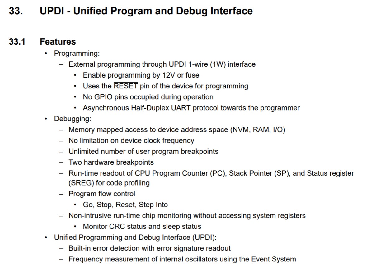
After reading these instructions, the basic principle and parameters of UPDI programming are clear to users. More detailed description are provided in the later part of the instruction for those users who would like to understand the deeper layer controlling mechanisms.
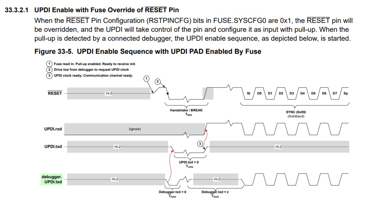
But for beginners like me, the brief introduction, which informs me about the appropriate voltage, pin connection, and the required environment for UPDI programming, has been more than adequate.
Embedded Programming
I have used Arduino IDE to program the ATTiny 1614 board for reading the input from the serial port and translate the input into the destination of the motor to go. This is an essential function that my final project should achieve. As easy as this sounds, accomplishing this task actually requires some tricks to counter the ASCII code and digit issues.
The ATtiny 1614 board was programmed with the FT232 programmer that have been made in a previous week.
I frist thought get the serial input was as easy as these code:
                void setup() {

                Serial.swap(1);// to use alternative Rx/Tx, because I connected the wrong ones on my board

                Serial.begin(9600);    // opens serial port, sets data rate to 9600 bps

            }


            void loop() {

              // put your main code here, to run repeatedly:

              while (Serial.available()>0){

                int location = Serial.read();

                Serial.print("location: ");

                Serial.println(location);

              }

            }
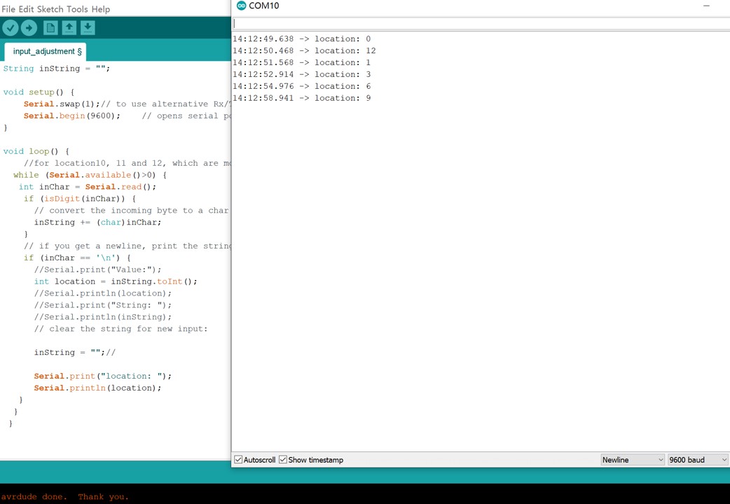
The logic seems to be obvious: the ATtiny 1614 chip reads the input from serial port and print the location. However, the result can be quite confusing if the code is written in this way.
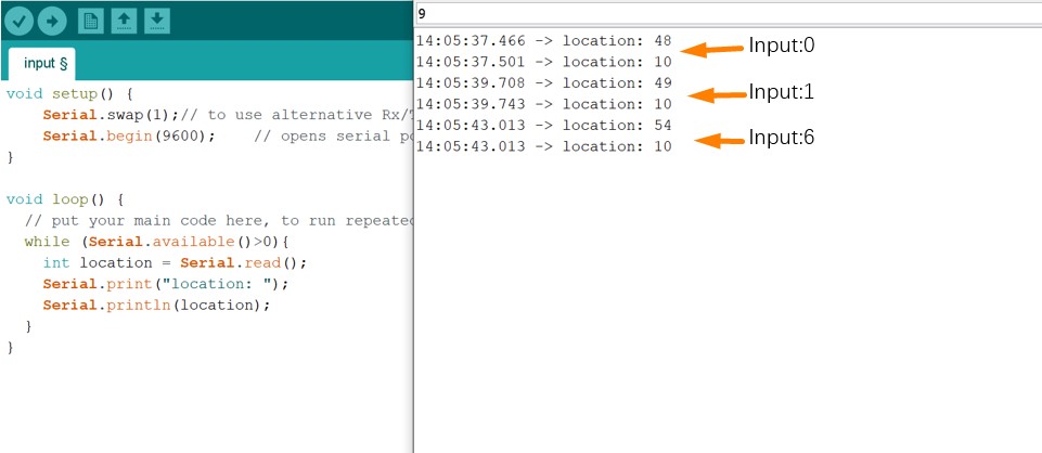
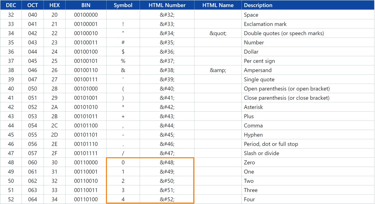
Such a result are due to two mechanisms of the Serial.read() and Serial.println() function.
1. Serial.read() returns the first byte of incoming serial data available, which means the location "12" will not be treat as a integer.
2. Serial.println() prints data to the serial port as ASCII texts instead of actual integer.
What makes the situation tricker is that the designated step count of my final project was exactly 48. It took me a while to figure out whether this issue was due to the serial communication or due to my step counting algorithms.
Thus, to counter these two problems, I have revised the code to:
1. Convert the incoming byte to a char, which solves the ASCII problem
int inChar = Serial.read();
isDigit(inchar);
2. Store the char in the string, which solve the digit issue when entering 10,11,12
inString += (char)inChar;
3. Convert the string into integer with .toInt() function.
int location = inString.toInt();
The full code are shown as follow.
        String inString = "";


        void setup() {

            Serial.swap(1);// to use alternative Rx/Tx, because I connected the wrong ones on my board

            Serial.begin(9600);    // opens serial port, sets data rate to 9600 bps

        }


        void loop() {

            //for location10, 11 and 12, which are more than 1 byte

          while (Serial.available()>0) {

           int inChar = Serial.read();

            if (isDigit(inChar)) {

              // convert the incoming byte to a char and add it to the string:

              inString += (char)inChar;

            }

            // if you get a newline, print the string, then the string's value:

            if (inChar == '\n') {

              //Serial.print("Value:");

              int location = inString.toInt();

              //Serial.println(location);

              //Serial.print("String: ");

              //Serial.println(inString);

              // clear the string for new input:


              inString = "";//


              Serial.print("location: ");

              Serial.println(location);

           }

          }

         }
The adjusted code can now function well with the serial input and displays.
Functioning Video
Files
Arduino Code:
● Read_Serial.ino