Individual Assignment
The individual assignment of week is about writing an application that interfaces a user with an
input &/or output device. Due to the constrains in hardware, I have tried several different approaches, including using MIT APP Inventor, Blynk, and Processing 3.
Due to the limitations in hardware, my interfaces based on MIT APP Inventor and Blynk may not fully align with this week's objectives, so I eventually chose to build an interface with Processing.
MIT APP Inventor
In this week, I first tried to create an own Android App to control Arduino LED based on this tutorial, because I do not have necessary Bluetooth module hc-05 yet, so I finished the procedures that do not involve this module. More details will be updated when the hc-05 module is available.
1. APP Interface Design
The APP is designed based on MIT APP inventor.
After log in, create a project by clicking Start new projecton the top left menu.
To use this APP to control Arduino LED, there are totally 6 modules needed in this APP.
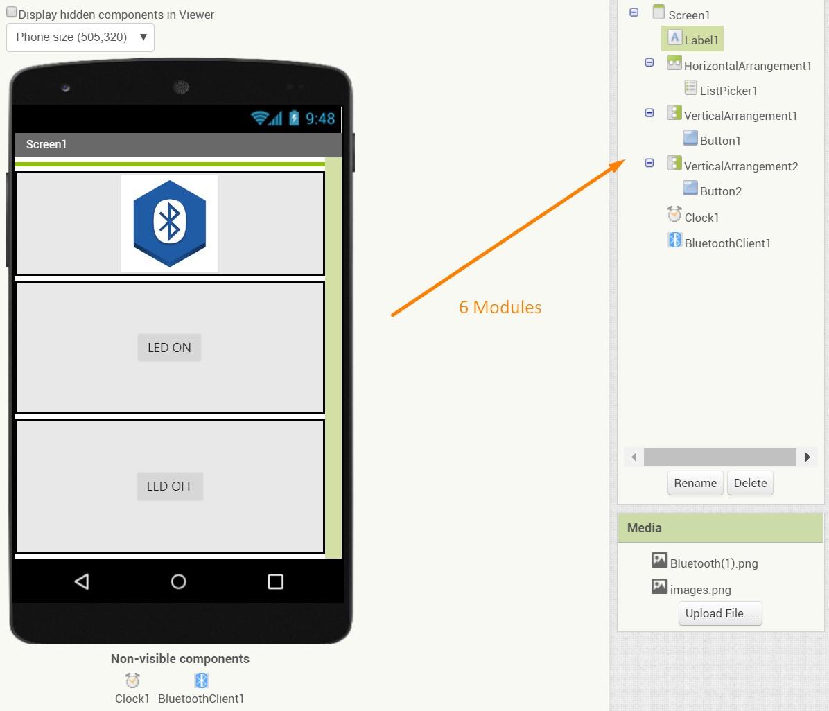
1.1 Visible Modules:
Label: Shows the Bluetooth Connection status
Add:Left Menu>>User Interface>>Label
Modify:Right Menu>>Width=Full Parent
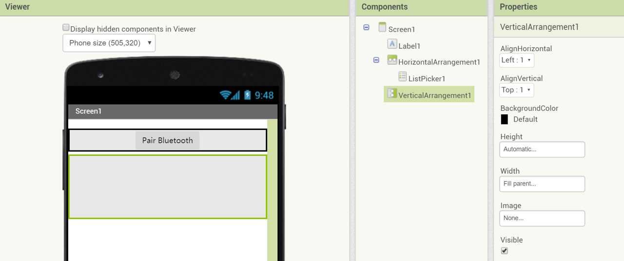
ListPicker : Connect Bluetooth
Add:Left Menu>>Lay out>>Horizontal Arrangement>>User Interface>>List Picker
Modify:Right Menu>>Horizontal Arrangement >>Width=Full Parent
Melioration: Right Menu>>List Picker>>Image>>Height=Width=100 px
Button 1 : Light up the LED
Add:Left Menu>>Lay out>>Vertical Arrangement>>User Interface>>Button
Modify:Right Menu>>Vertical Arrangement >>Width=Full Parent>>AlignHorizontal/Alignvertical=Center
Text:Right Menu>>Button 1>>Text="LED ON"
Button 2 : Turn off the LED
Add:Left Menu>>Lay out>>Vertical Arrangement>>User Interface>>Button
Modify:Right Menu>>Vertical Arrangement >>Width=Full Parent>>AlignHorizontal/Alignvertical=Center
Text:Right Menu>>Button 2>>Text="LED OFF"
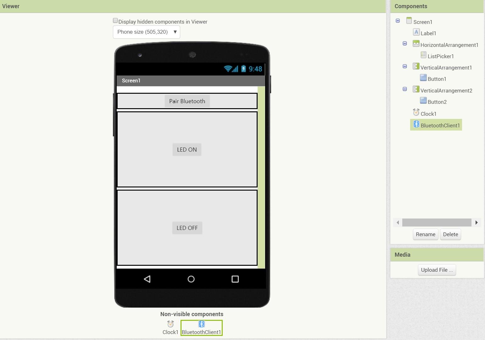
1.2 Invisible Components
Clock Sensor
Add:Left Menu>>Sensors>>Clock
Bluetooth
Add:Left Menu>>Connectivity>>Bluetooth Client
2. Logic Block
The next step is to arrange the logic blocks behind the interface.
User can change to the block section by clicking the Block tab on the right top corner. By draging and stacking different block components together, the logic block are connected.
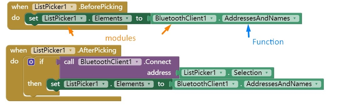
2.1 List Picker
There two blocks about the List Picker: Before and After Picking.
2.2 Clock Timer
The central logic of the clock timer block is a If-Then structure that help to distinguish and demonstrate whether the bluetooth is connected or not.
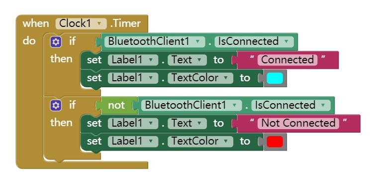
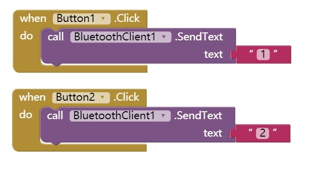
2.3 Buttons
The central logic for buttons is just "when being pressed, do send text".
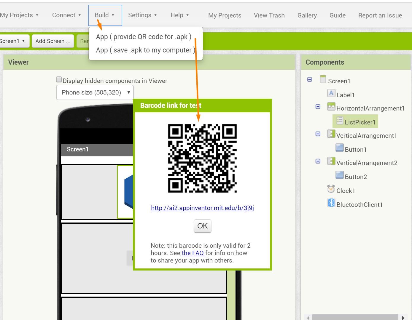
Then the APP is ready to be download. By clicking Build Tab >> APP(QR code) ,an QR code than be generated that allow the users to download the APP to Android devices.
The following steps will require the hc-05 module, which I do not have now. Moreover, because I do not have Android device, the following steps, especially the installation, has been a trouble. Thus, after several unsuccessful attempts in using simulator, I have changed to other strategies in creating applications and interfaces.
Blynk
Blynk is platform that allows users to quickly build interfaces for controlling and monitoring hardwares for both IOS and Android systems, which is much friendly to iPhone users.
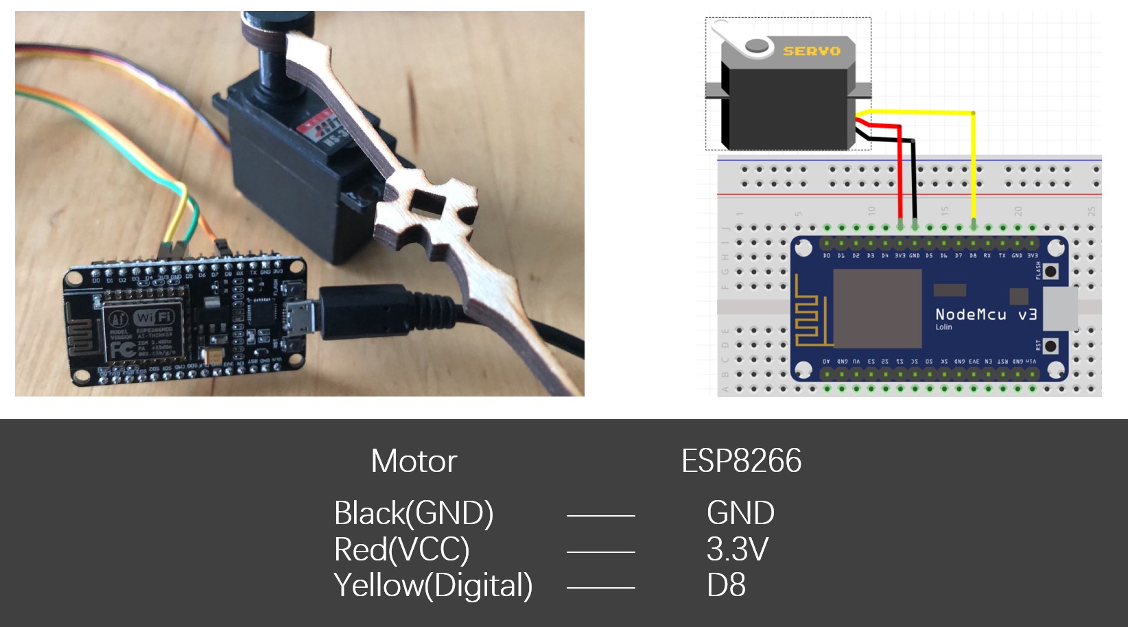
Following this tutorial, with an ESP8266 dev board, I managed to create an Blynk interface that controls the rotation angle of a HS-322HD servo motor.
1. Wire the devices
The board connection is straightforward.
-Black Line ---> GND
-Red Line ---> 3V3
-Yellow Line ---> D8
Any digital pin can be used in this case.
2. Creating Blynk Interface
Creating a Blynk Interface can be very efficient.
a. Create Project
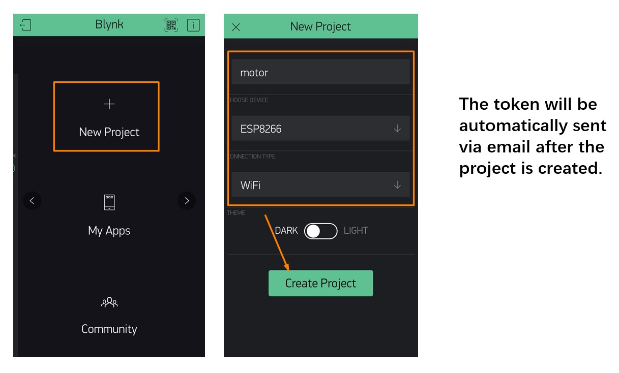
The first step is to create a new project in the Blynk App installed in my phone.
Simply following this procedure will allow users to create new project.:
New Project >> Input Project Name>>Choose Device>>Connection Type
b. Adding Widgets
The second step is to add widgets to the interface.
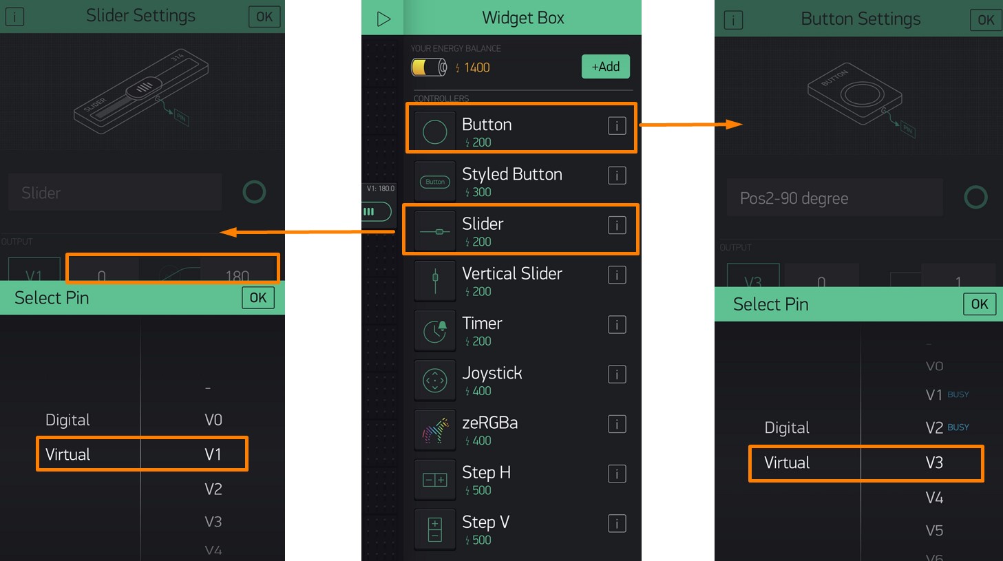
- Adding Slider
I used a slider to control the rotation angle of the servo motor.
Clicking the Slider widget allows this components to be added to the interface.
Output:
Pin: Virtual >> V1
Range: 0 - 180
- Adding buttons
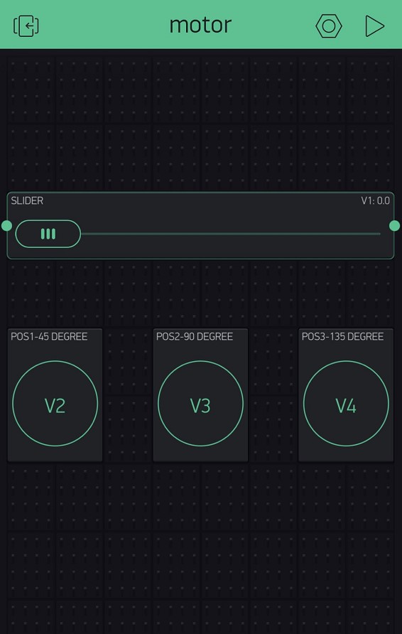
I also added 3 buttons that allows the motor efficiently turn to 45°, 90°, and 135°.
Clicking the Button widget can add this components to the interface. For each button, only the pins are needed to be assigned, the widget names are not essential.
Output:
Names: POS1-45 Degree/POS2-90 Degree/ POS3-135 Degree
Pins: Virtual >> V2/V3/V4
At this stage, assigning the pins are enough, because the actual rotation degrees are determined in Arduino code.
The Virtual Pins are used here for conveninece. Instead of digital pin that maps to the actual pins on designated hardware, using virtual pins supports interfacing with any devices. Virtual pin is like a programming variable of which the values can be set by users according to needs and hence provides more freedom in using Blynk.
c. Programming
I used an ESP8266 dev board in this task, while I later found that I should not and again took an alternative approach. But in the case of using ESP8266 dev board, programming with Arduino IDE was quite simple.
The following code are used:
Blynk Code
        #define BLYNK_PRINT Serial

        #include <ESP8266WiFi.h>

        #include <BlynkSimpleEsp8266.h>

        #include <Servo.h>


        Servo servo;


        char auth[] = [Blynk Auth Token];

        char ssid[] = [Your Wi-Fi ssid];

        char pass[] = [Your Wi-Fi password];

        void setup()

        {


          Serial.begin(9600);

          Blynk.begin(auth, ssid, pass);

          servo.attach(2); // NodeMCU D8 pin

         }


        void loop()

        {

          Blynk.run();

        }

        BLYNK_WRITE(V1)

        {

           servo.write(param.asInt());

        }

        BLYNK_WRITE(V2)

        {

          servo.write(45);

        }
        BLYNK_WRITE(V3)

        {
          servo.write(90);

        }
        BLYNK_WRITE(V4)

        {
          servo.write(135);

        }
This short code first connects the NodeMCU board to Blynk by verifying the token, Wi-Fi ssid and password. Then, the motor used for this code is designated by the servo.attach() function.
BLYNK_WRITE(V1) determines the function of the slider widget, which controls the motors to turn to any input position between 0° to 180°.
BLYNK_WIRTE(V2-V4) determine the function of the three button widget, which control the motor to turn to three set position: 45°, 90°, 135°.
Functioning Video
However, it was not until later that I found we will need a self-made board to accomplish this week's tasks. Thus, I have tried the third approach: creating an interface with Processing.
Processing
Processing is an open-source IDE that provides strong support to both visualization and electronic modules. Processing is highly compatible with Arduino IDE, which makes it quite easy to acquire the basic programming skills for one software if the user is familiar with another.
I have used my ATtiny 412 board that I made in the Electronic Design week and the same HS-322HD servo motor I used in the previous task.
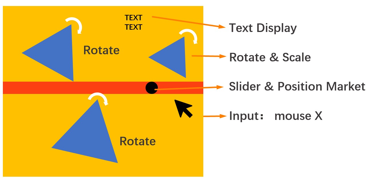
My interface is simple and can accomplish the following functions:
- Control speed and image scale with the position X of the mouse: Left:Slow + Right:Fast
- Control range of motor rotation with the position X of the mouse: Left:0° + Right:180°
- Display the angle of motor rotation on the interface
- When angle>=90°, display "Speed Up" on the interface, otherwise display "Slow Down" on the interface
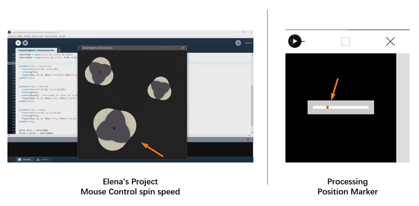
This project was inspired by:
(1)ELENA CARDIEL's Application and Interface Programming documentation in 2019, and
(2) Processing's official tutorial in controlling servo motor with Processing and Arduino IDE.
Elena's project uses the position X of the mouse to control the speed and image scale of three flowers on the interface: the more the mouse is to the left, the flowers will spin in a slower speed and vice versa. The Processing's official tutorial illustrates how to use a position marker to control the rotation angle of servo motor.
I think it may be fun to mix the features of these projects together and create an interesting motor control interface.
Step 1. Structuring the Interface
The first step is to determine the structure of the interface and figure out the function and features required by each module.
In the simplest version, my interface can be summarized in this way:
- Input:
Mouse Position (X)
- Output:
● Control Image: (1) rotation speed, (2) scale
● Control Motor: rotation angle
● Display Information: rotation angle and other information
Thus, by drafting the code of each of these modules and synthesizing those episodes together, I can roughly construct the interface.
A. Input: Mouse Position
The mouse, or cursor, position is a very commonly used variable in Processing, so the way to get this information is quite simple.
mouseX //always contains the current horizontal coordinate of the mouse.

        mouseY// always contains the current vertical coordinate of the mouse
B. Image
This module is modified based on Elena's project. These functions have been applied:
             -PImage:  variable container for image.

            -loadImage(): to load an image.

            -translate(): to assign the position to objects

            -rotate() to rotate objects.

            -scale(): to change the scale of objects.

            -pushMatrix(), popMatrix(): Features between these two functions are treated locally instead of globally

            -rectMode(CORNERS): to easier define the location of the slider bar
C. Motor
This module is based on Processing's tutorial, while these function and syntax are used:
Connect to serial port
port = new Serial(this, Serial.list()[0], 9600);
Calculate rotation angle
float mx =0.0
-The map() function re-maps a number from one range to another.
...
int angle = int(map(mx, 20, 1260, 0, 180)); // Scale the value to the range 0-180
port.write(angle);
For example, in this case, the mouse position X [mx] is converted from a value in the range of 20 to 1260, which is the width of the interface, into a value that ranges from the left edge of 0° to the 180°.
D. Display
This module involves the display of images, position marker, and texts.
* The earlier a components appeared in the code, the deeper layer it would be positioned.
-Images
        //define

        PImage [image variable]

        //use

          pushMatrix(); //pikachu1 left up corner

             translate(width/5, height/5);

             rotate(cw);

             image([image variable], 0, 0, [image variable].width/3, [image variable].height/3);

          popMatrix();
-pushMatrix() and popMatrix() are used to control the scope of the transformations.
In some sense,the conjuction usage of pushMatrix() and popMatrix() can be seen as functions that make a transformation local instead of global. The pushMatrix() function saves the current coordinate system to the Matrix stack and popMatrix() restores the prior coordinate system.
-rotate() function is used to control the rotation of an object. Angles must be specified in radiansor to be converted from degrees to radians, which ranges from 0 to 2π.
In my case, I have converted the mouse speed into radians to control the rotation.
- Position Marker
The track is simply a rectangle that has no solid restriction on the parameters.
rectMode(CORNERS);//define by the coordination of two diagnal points
The marker itself is a rectangle that related to the mouse position:
fill(252,64,18);
noStroke();
rect(x1,y1,x2,y2);//coordination of the two diagnal points
image(pokeball, mx-2, y, width, height);
- Text
              textFont(font,size);

              text("word", x,y);
Step 2. Interface Design
After establishing the structure of the code, more aesthetic elements can be handled in the second step.
I decided to use Pikachu as the image that will rotate as cursor moves and hence used a Poke ball as the position marker. Both images are retrieved from free icon websites. A free Pokemon font was also added to the program.
The colors used for background and other elements are abstracted by color picker tool.

To better support the visualization and interpretation process of the information demonstrated on the interface, two lines of texts are display on the canvas.
The first line indicates the angle of the motor rotation, which directly reads from the serial port.
The second line indicates the speed of the image rotation. I set 90 degree as a threshold.
- Angles ≥ 90°: "Happy Pikachu Speed Up"
- Angles <90°: "Tired Pikachu Slow Down"

Step 3. Programming
The electronic-related programming is usually done in Arduino IDE, while the interface-related programming is done in Processing IDE.
In my case, the Arduino based programming are very simple, which only involves assigning pins of ATtiny 412 and read the value of rotation angle from the serial port. The Processing based programming are slightly more complex, which synthesizing the previously structured code blocks.
* Caution: If the Processing code contains port-related elements, it will not run without connecting to the electronics.
Both Arduino and Processing code are listed as follow:
Arduino Code
               // Read data from the serial port and set the position of a servomotor
                // according to the value
                //
                #include <Servo.h>


                Servo myservo;                   // Create servo object to control a servo

                int servoPin = 3;                // Connect yellow servo wire to digital I/O pin 3 (TX)

                int angle = 0;                   // Container for the integers of rotation angle sent via port


                void setup() {

                  myservo.attach(servoPin);      // Attach the servo to the PWM pin

                  Serial.begin(9600);           // Start serial communication at 9600 bps

                }


                void loop() {

                  if (Serial.available()) {      // If data is available via port,

                    angle = Serial.read();       // read the integer sent by Processing via port and assign it to variable angle

                                                 // The angle sent from port has been scaled into integers between 0 to 180 in Processing

                  }

                  myservo.write(angle);          // Set the servo position by reading the integer angle

                  delay(15);                     // Wait for the servo to get there

                }
Processing Code
                    PImage pikachu; //load Pikachu

                    PImage pokeball; //load Pokeball

                    PFont font;//input font

                    float cw;//clockwise

                    float ccw;//counterclockwise

                    float mouse_speed_cw;

                    float mouse_speed_ccw;

                    float zoom;//zoom one of the pikachu to visually emphasize the rotation speed

                    float mx = 0.0;// motor control


                    import processing.serial.*;


                    Serial port;


                    void setup(){

                      size(1280,1280); //canvas szie

                      pikachu = loadImage("pika.png");

                      pokeball = loadImage("pokeball.png");

                      background(255, 177, 27);

                      font = createFont("PokemonSolid.ttf", 48);

                      port = new Serial(this, Serial.list()[0], 9600);

                    }


                    void draw(){ //esto se ejecuta en bucle

                      background(255, 177, 27);//canvas color

                      imageMode(CENTER); //set the zero point at the center of the canvas


                      zoom = map(random(mouseX/2), 0, width, 0.5, 2);

                      mouse_speed_cw = map(mouseX, 0, width, 0, 0.5);//Calculate rotation angle

                      mouse_speed_ccw = map(mouseX, 0, width, 0.05, 0.3);


                       //motor

                       //Position marker track

                      rectMode(CORNERS);

                      fill(252,64,18);

                      noStroke();

                      rect(0,640,1280,690);

                      //position marker

                      fill(20);

                      //circle(mx-2,665,45);

                      //pushMatrix();

                      image(pokeball, mx-2, 665, 45, 45);

                      //popMatrix();

                      float dif = mouseX - mx;

                      if (abs(dif) > 1.0) {
                        mx += dif/4.0;

                      }

                      mx = constrain(mx, 20, 1260); // Keeps marker on the screen


                      int angle = int(map(mx, 20, 1260, 0, 180));  // Scale the value to the range 0-180, so the angle sent to port will be an integer

                      print(angle + " ");                        // Print the current angle (debug)

                      port.write(angle);


                      textFont(font);

                      text("Angle:", 680,100);

                      text(angle, 900, 100);


                      if(angle >90){

                      text("Happy Pikachu Speed Up", 670,200);


                      } else{

                      text("Tired Pikachu Slow Down", 670,200);

                      }


                      pushMatrix(); //pikachu1 left up corner

                        translate(width/5, height/5);

                        rotate(cw);

                        image(pikachu, 0, 0, pikachu.width/3, pikachu.height/3);

                      popMatrix();


                      pushMatrix(); //pikachu2 right up corner

                        translate(width/1.33, height/2.81);

                        rotate(cw);

                        scale(zoom); //escalamos el valor de la escala

                        image(pikachu, 0, 0, pikachu.width/5, pikachu.height/5);

                      popMatrix();


                      pushMatrix(); //pikachu3 left bottom corner

                        translate(width/2.5, height/1.4);

                        rotate(ccw);

                        image(pikachu, 0, 0, pikachu.width/2, pikachu.height/2);

                      popMatrix();


                     cw= cw + mouse_speed_cw;

                     ccw =ccw - mouse_speed_ccw;


                }
Step 4. Testing & Debugging
Due to the limitations in available pins of my ATtiny 412 board, I used a Rx/Tx hub that drived from Jari's archive. When I design the ATtiny 412 board, I did not leave extra pin outs for additional usage, so in this case, if I direct use FTDI cable, I will not be able to connect the pins to the motor. Thus, I connected the Rx,Tx,VCC, and GND pins of the ATtiny 412 board and the digital, VCC, and GND pins of motor to the Rx/Tx hub and connect the Rx/Tx hub with the computer with the FTDI cable.
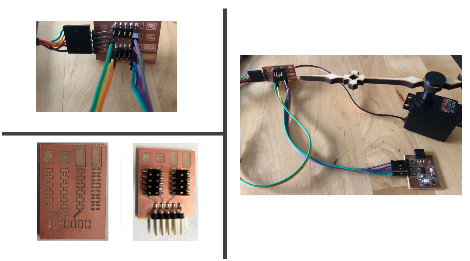
In this way, I can connect the motor to the ATtiny 412 board by connecting
Motor GND(black) - ATtiny 412 GND
Motor VCC(red) - ATtiny 412 VCC
Motor Digital(yellow) - ATtiny 412 Rx (Pin 3)
Because the code blocks are tested respectively, the code works well after several small modifications.
The functioning records of the interface alone, as well as the interface + devices, are demonstrated as follow.

Trouble Shooting
Due to the lack of knowledge, I have encountered many problems in this process and decided to list them here for potential future reference.
1. Determining the method to use
As mentioned above, I did not plan to try three different applications or software at first. It was until I found my devices were not compatible with the tool or I found the interface does not fully comply with the requirement did I change to a new method.
Thus, it seems to be a very good idea to first check the requirements of weekly assignment when ideating the content of the assignment.
If I realized that this week's assignment requires us to use the input or output devices that we made, I will not use ESP8266 NodeMCU when using Blynk. Also, for IOS users, it is important to realize that the MIT APP Inventor requires Android device. Users without Android device and do not know how to use Android simulators might not consider this method.
Due to the limitations in hardware and device, I eventually solved this problem by using Processing, which has minimal requirement on the device and enables flexible design of the interface.
2. Learn Processing Syntax
While the syntax of Processing is similar to Arduino, it still requires some effort to navigate for novice. Fortunately, the Processing website provides great tutorials.
In my case, Electronic tutorial is a great chapter to start. This chapter provides some examples of controlling electronic components with simple interfaces. I adopted the idea of controling motor rotation with a slider bar from this tutorial.
For pure novice like me, I personally suggest to start to learn Processing syntax by replicating a basic example before diving into the functions and references. It is easier to interpret the functions after seeing its outcome.
3. Interpreting the code
As mentioned above, my interface was built with reference to Elena's project and Processing's official tutorials. While I can understand the logic of the code, not all details are clear to me at first. I solved this problem mostly by changing the parameters and learning from the outcomes, which makes many problems straightforward.
4. Problems with devices
Besides the IOS and NodeMCU issue, I also encountered problems in using my ATtiny 412 board. When I design this board, I did not reserve extra pins for this purpose and hence cannot be directly connected to board. Thus, I used an Rx/Tx hub as a connector to link the motor and the microcontroller.
Group Assignment
The group assignment of this week focus on comparing as many tool options as possible. Please check our Group Assignment Page for more details.
Files
Blynk:
● Arduino_Blynk.ino
Processing:
-Display
● Pikachu.png ● Pokeball,png ● Pokemon_solid_Font
-Code
● Processing.zip
● Pikachu_motor.ino