Final Project: Modern Weasley Clock
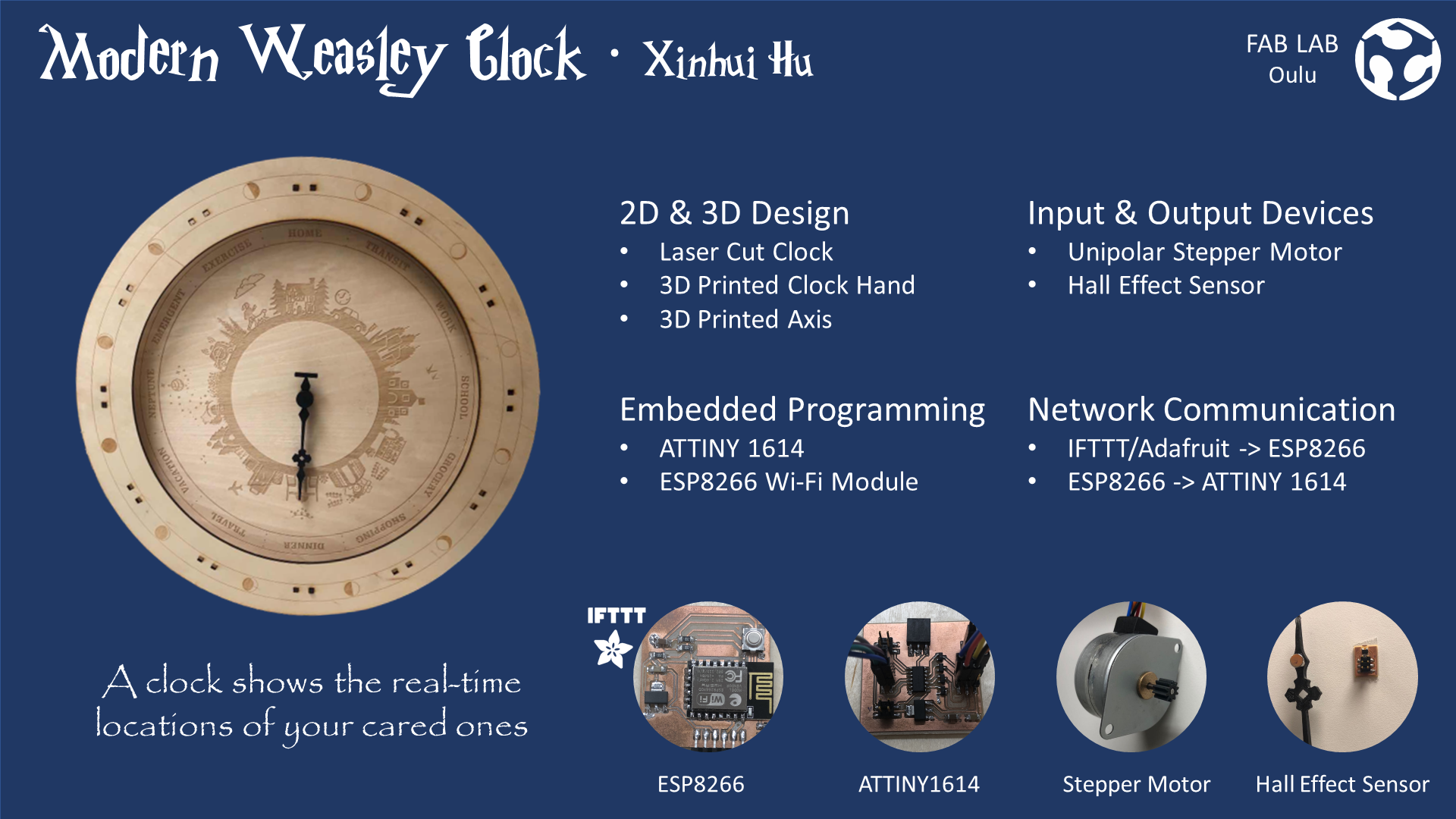
For the final project, I have created a prototype of a modern Weasley clock, which derives from the magic clock that belongs to the Weasley family in Harry Potter.
Images credit
Music credit: 新世紀エヴァンゲリオンBGM: 次回予告
Ideation
Weasley Clock automatically tracks and shows the read-time location of Weasley family members. Based on the IFTTT-Adafruit IO - ESP8266 - ATtiny 1614 communication chain, I was able to replicate the major function of this Wealey's Clock and create a modern version.This page is a brief introduction to this project, which includes the iterative ideation, conceptual design, embodiment design, and prototyping processes.

This is a magic clock that belongs to the Weasley's family in Harry Potter. This clock has nine golden hands, each of which represents a member of their household. Instead of time, the clock displays the locations, including "home","school","working","in transit" and other possible locations. The golden clock hand of each member will automatically detect the location of the corresponding member and point to the location. While we, the non-magicians, have owned much more convenient devices, like phones, to stay connected, it would be nice for us to have such a clock in our lives that enhance the sense of belonging and connection.
There are two major reasons for me to choose this idea for the final project.
On the one hand, the need for emotional connection and support has been increasing among modern humans. Communication vias mobile devices did make everyone available to each other. However, such a connection requires an active effort to maintain, which sometimes brings mental burdens. Also, trivial but repetitive conversations over the same topic, like confirming each other's schedule, can be quite exhausted for the busy modern people. Thus, an unintrusive and effortless way to maintain the connection among cared ones may be appreciable.
On the other hand, a clock seems to be within the feasible scope of Fab Academy, which definitely involves laser cutting, 3D printing, embedded programming, network and communication, as well as other topics covered by the courses. Thus, I hope to develop a product that can address this gap, to which the Weasley's clock seems to be perfect.
Conceptual Design
In the conceptual design stage,the functions and underlying mechanisms are determined.The logic and functions are emphasized in this stage, the technical details and implementation are included in the later Embodiment Design Section.
Function Design
The modern Weasley Clock should fulfill these two major functions:
● Automatically detecting the current location of users via mobile devices
● Visualizing the locations on the clock to inform the other members
Ideally, including these features in the clock will make it a better product. Due to the time and scope, the mechanisms have been explored but the features will be integrated in future iterations.
● It will be nice if the clock can indicate the location of multiple users at the same time.
● It will be nice if the clock can alert all connected users if one users triggered the emergent status
● It will be nice if the clock can send weekly report to the users about the time they spent in each location to promote work-life balance
12 locations are determined based on daily life experience:
● Home
● Transit
● Work
● School
● Grocery
● Shopping
● Dinner
● Travel
● Vacation
● Neptune
● Emergent
● Exercise
In this case, the location Neptune does not refer to the remote planet at the edge of the solar system but is used as a metaphor of somewhere "far, mysterious, and free." Users can label places that they feel safe, fun, and relaxing as "Neptune." Thus, the family members will know that they do not need to worry about this person and do not need to invade their personal spaces.
Emergent is also a specially designed status, which should only be triggered when the users' mobile devices are in emergent mode.
Mechanism Design
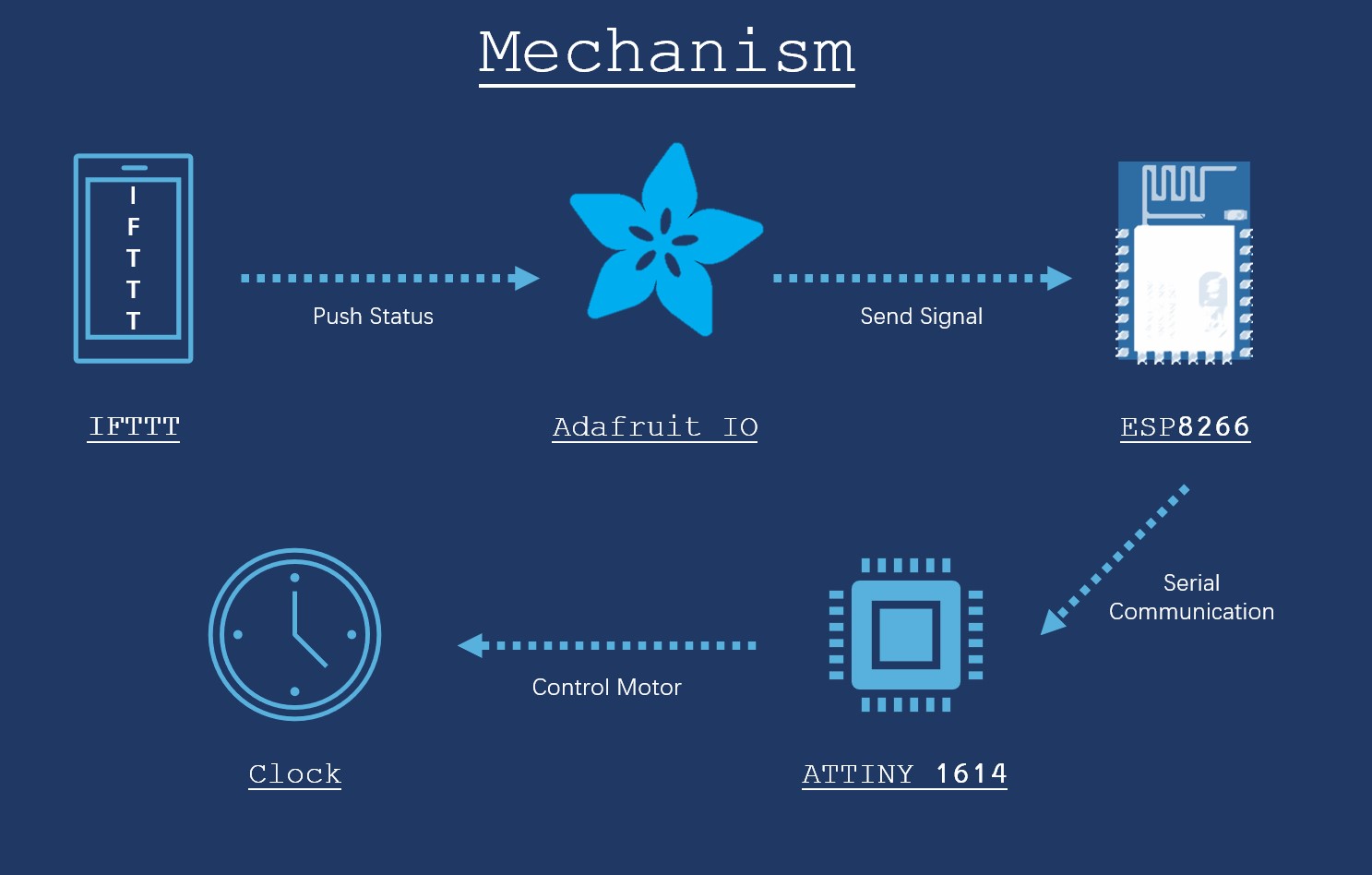
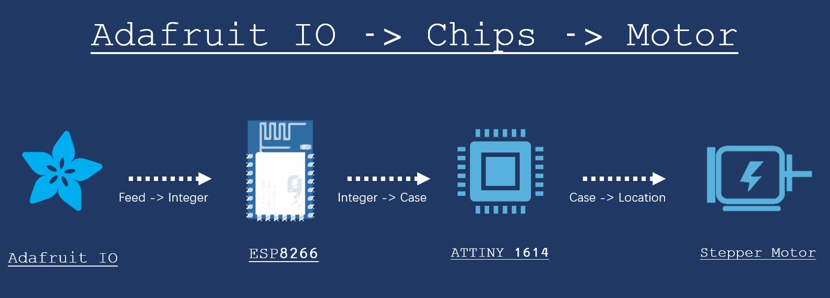
As shown in the figure, this project adopts such a strategy:
Step 1. Mobile Phone Application IF This Then That (IFTTT) detect the GPS location and create a trigger.
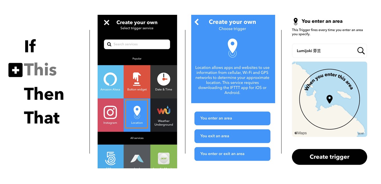
The creation of applet has been quite straightforward.
First, by following the +This >> Location >> Create Trigger when enter/exit an area >>[Enter the address] >>Create procedures, a trigger is generated.
In my case:
● Home => Trigger when entering the area near home
● Transit => Trigger when exiting home and workplace/school
● Work => Trigger when entering the area near my office
● School => Trigger when entering the area near the University
● Grocery => Trigger when entering the area near supermarkets nearby
● Shopping => Trigger when entering the area near the shopping mall in the city center
● Dinner => Trigger when entering the area near my favorite restaurant
● Travel => Trigger when entering the area of airport and railway station
● Vacation => Trigger when entering the area near national park
● Neptune => Trigger when entering the area near locations that are labled with Neptune
● Emergent => Trigger when the phone is in emergent status
● Exercise => Trigger when entering the area near gym
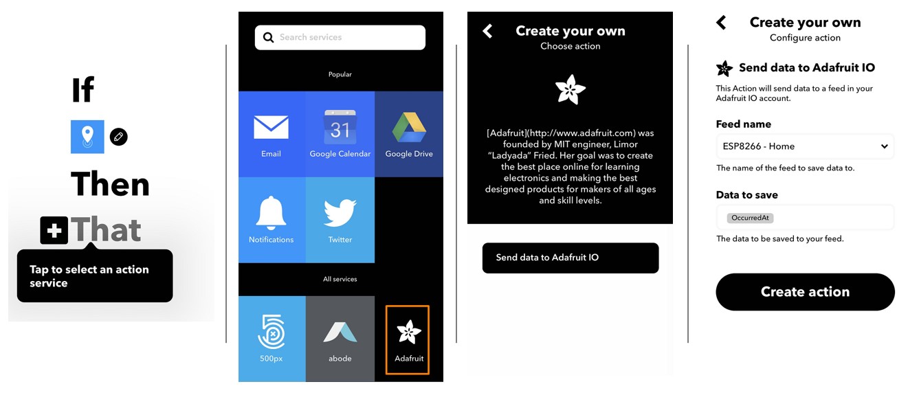
Step 2.When trigger is activated, push the status to Adafruit IO feed
This strategy is invented by our instructor Iván.
In most of the existing tutorials, this step is accomplished by built-in functions of developed board like Particle Photon or ESP8266 dev board, which is not an available choice for those who wants to design their own board.In this case, Iván's tutorial has provided a great strategy, which is to use Adafruit IO as a bridge between IFTTT and the clock ESP8266 module.
After signing in Adafruit IO, Feeds >> Actions >> Create New Feed will allow users to easily create new feed.

Then, in IFTTT, link the IFTTT account with Adafruit account. In the "That" section, choose Adafruit IO and select the Feed name and the right type of Data to save. Therefore, the location can be detected and the data are ready to be pushed to the next module.
Step 3. Push data from Adafruit IO to ESP8266
In this stage, an ESP8266 12F Wi-Fi module is used to grab the sigbal sent by from Adafruit Feeds. There are three major tasks for ESP8266 to accomplish in this process.
- Connect to Wi-Fi
- Connect to Adafruit
- Get() information from the Feeds
- Translate location information into case numbers
More technical details and codes will be presented in the later embodiment design section.
Step 4. Sending data from ESP8266 to Microcontroller via Serial Communication
An ATtiny 1614 chip has been used as the microcontroller in this project. Thus, simple by connecting the GND,VCC, Rx, and Tx pins of ESP8266 and ATTiny, the connection can be built. Then the ATTiny 1614 will control the motor to move to the correct locations More details regarding the serial communication are included in the embodiment design section.
Step 5. ATTiny 1614 and Output Devices
In the conceptual design stages, I have considered two different versions of output device: motor or LED lights. The former indicate the location by turning the clock hand while the latter use a light-up LED to show the location. Most of the previous projects that replicate the Weasley clock have chosen the LED strategy, because controlling multiple clock hands has truly been a tough task.
I have considered both motor and LED strategies and eventually chose the motor strategy when building this prototype, which is mainly because it is more similar to its orginal version. But instead of making several clock hands, I decide to first figure out how to control individual clock hands in this version.
In regard to the mechanism of controlling multiple clock hands, I think using multiple layers of the axis may be one way to achieve this goal. In this case, each clock hand will attach to different layers of the axis cylinders that controlled by different motors via gears or other mechanic parts.
Embodiment Design
Clock
3D Design
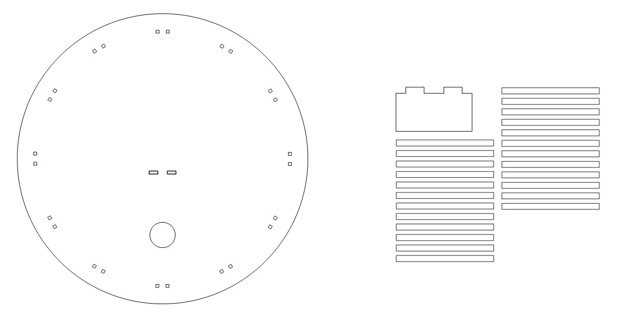
The clock consists of three layers.
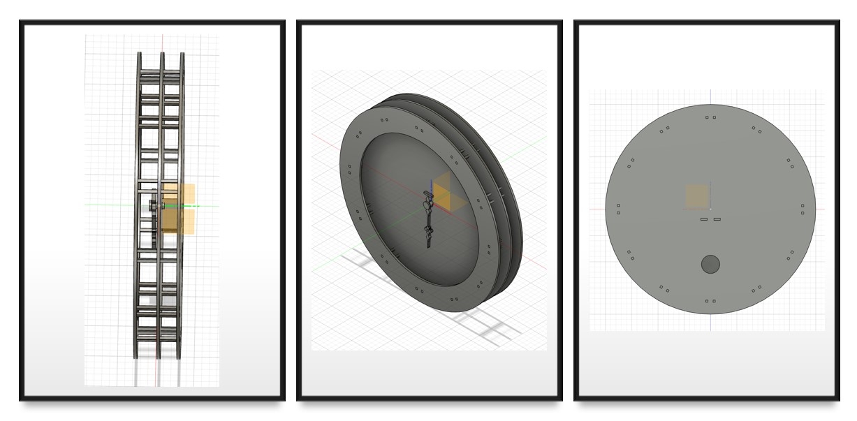
- The front layer is a halo around the clock face, which is designed main for improving the stability of the structure and for aesthetic concerns.
- The middle layer serves as the clock face, on which the patterns of each location are engraved.
- The back layer mounts the circuit boards and motor, the hole on the back board was reserved for possible cables.
These three layers are connected by 24 rods. Between the middle and back layers, a tiny platform will hold the motor.
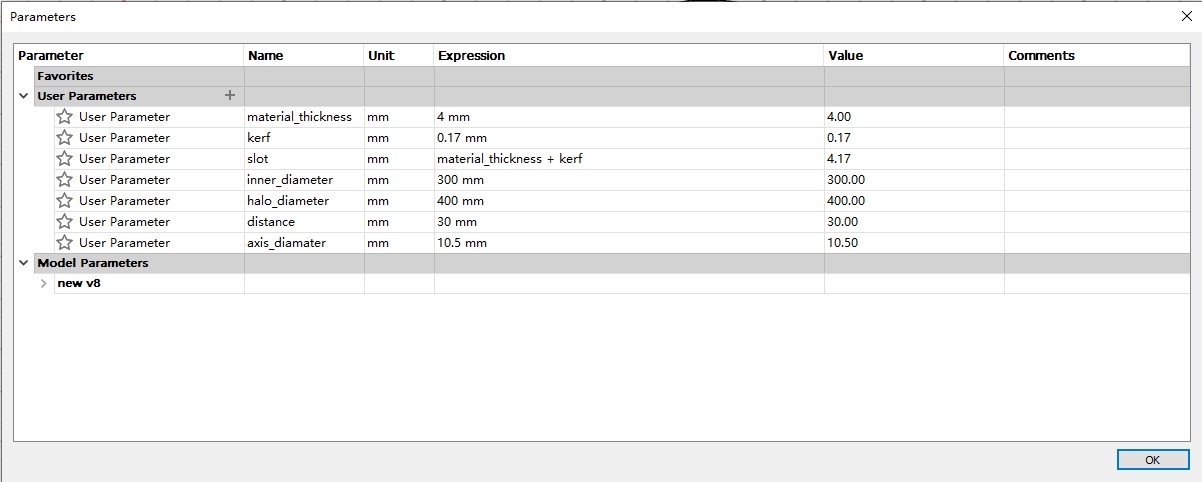
1. Parameter Definition
I used 4mm Plywood for the clock body and determined the parameters accordingly. The parameters regarding the axis are decided based on the measurment of the motor.
●Material_thickness: 4 mm
●Kerf: 0.17 mm
●Sloth_width: 4± 0.17 mm
●Inner_diameter: 300 mm
●Halo_diameter:400 mm
●distance: 30 mm [distance between two boards]
●axis_diameter: 10.5 mm
2. Clock Structure Design
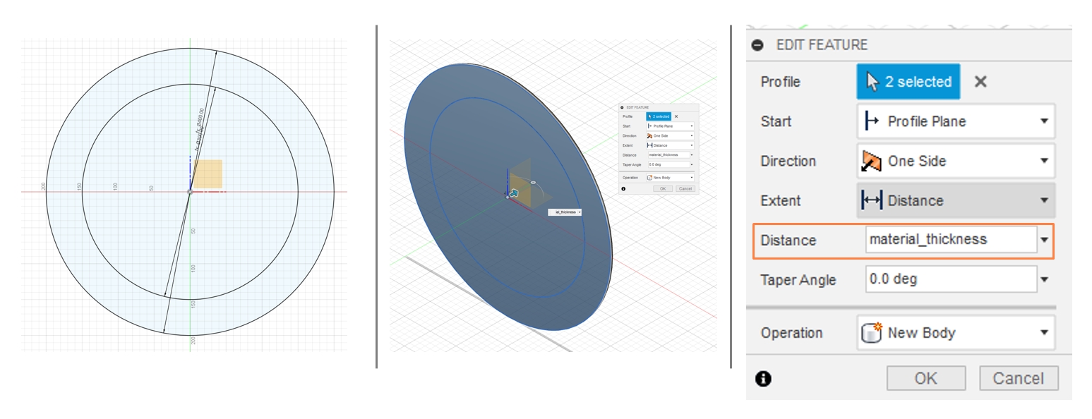
2.1 Clock Main Layer
The main layer of the clock is a circule with a diameter of 400 mm.
Sketch >> Circle >> diameter: halo_diameter [parameter=400 mm]
Extrude >> distance: material_thickness [parameter= 4 mm]
On the main layer of the clock should be:
- 1 middle round slots for clock hand axis: d= 10 mm
- 24 connection slots : 4.17 mm x4.17 mm
● The middle slot can be simply created by drawing a circle with diameter = 10 mm via
Extrude >> Distance: material_thickness >> Operation: cut
● A convenient way to create the 24 slots is to apply the Circular Pattern function. The first step is to create one rectangle with the edge length equal to material + kerf. I prefer the slots to be grouped by two instead of evenly distrubuted around the contour, so I made a mirrored copy of the slot.
Then select the four edges of the rectangle and follow these procedures:
Create >> Circular Pattern >> Center Point: circle center >>Quantity: 12
Repeat the procedures for the mirrored slots.
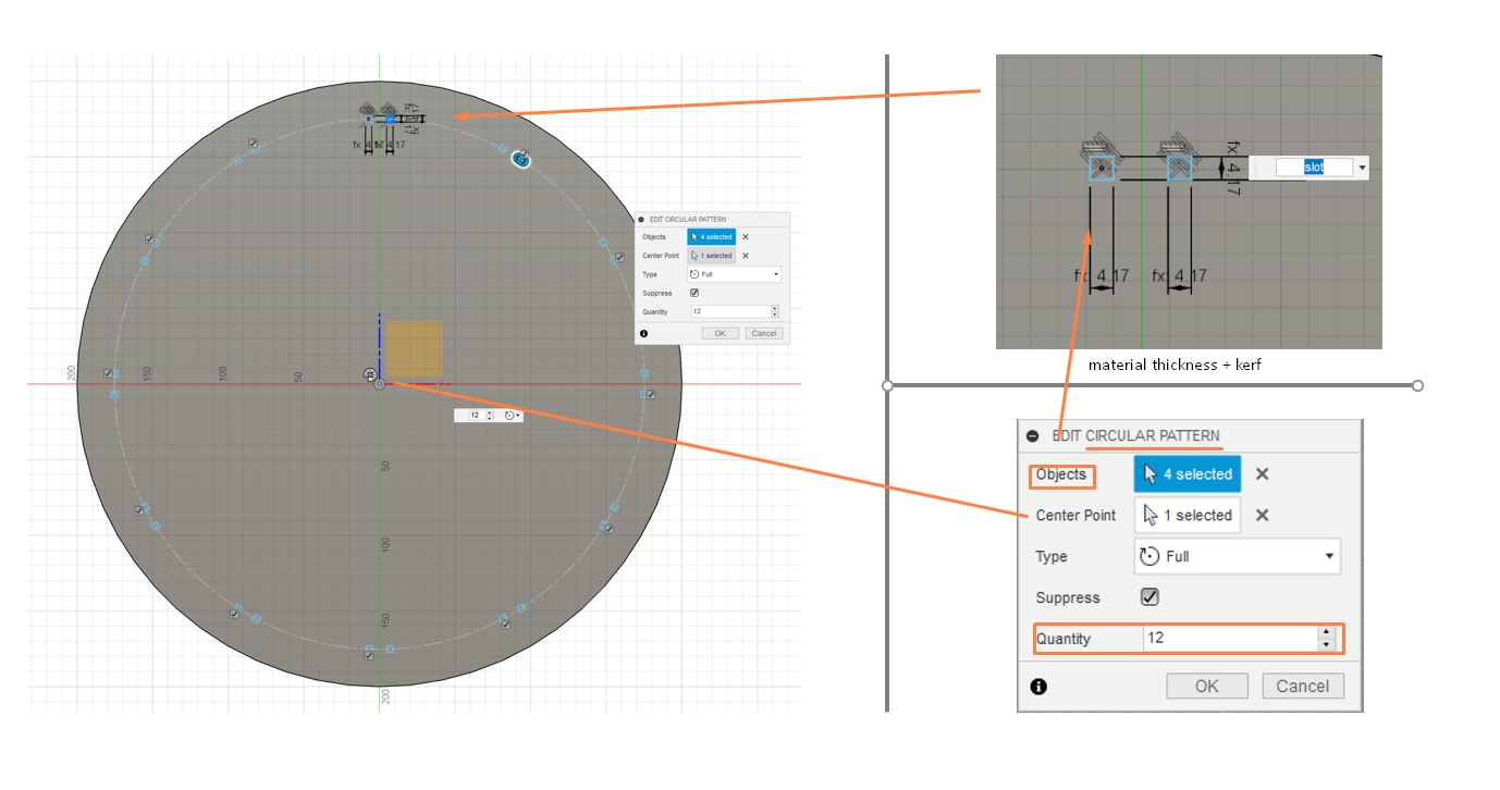
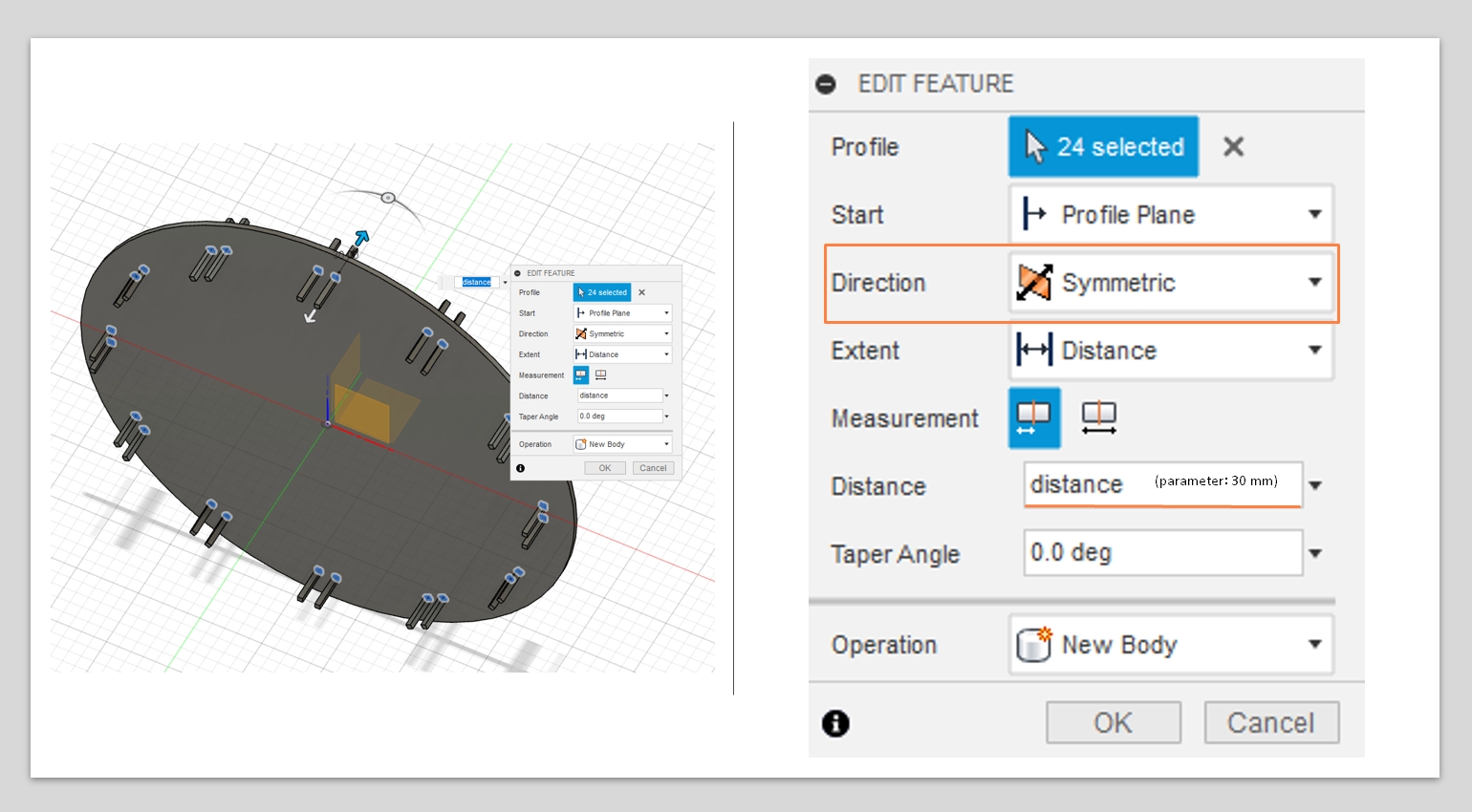
After creating the slots, the connection pieces can be directly extruded from the sketches. Select all 24 slots and Extrude with these parameters:
- Direction: Symmetric
- Distance: distance [parameter =30 mm]
2.2 Clock Halo
In front of the main layer is the halo layer, which is majorly included for aesthetic concerns.
The halo layer is a ring with:
- Outer Diameter: 400 mm
- Inner Diameter: 300 mm
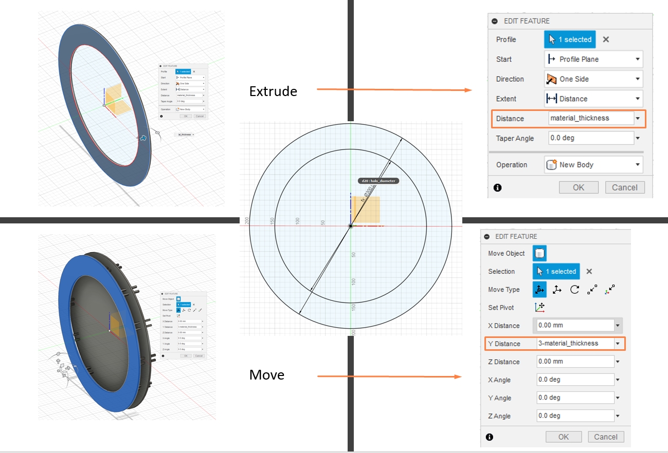
After creating the sketeches, the ring should be extruded by 4 mm, which is the material thickness. At the same time, the halo layer should be moved forward for 26 mm (30 mm -material thickness), which is calculated based on the size of the motors.
2.3 Back board
The back board will be used to hold the electronic board and motor used for this clock. A motor holder board is designed to be snaped into the back board. Additionally, a round slot should be left on the back board for the power cable to go through.
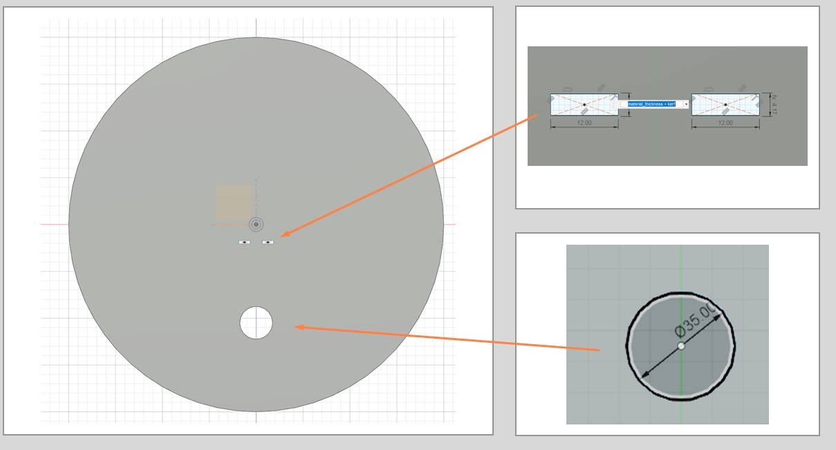
The snap slot has a length of 12 mm and a width of 4.17 mm (material thickness +kerf). The round slot has a diameter of 35 mm.
2.4 Motor Holder
The board just need to be slightly larger than the motor. Thus, the size of the holder totally depends on the types of the motor used in the project. A Jameco Unipolar Motor is used in this project. It is a good idea to leave two slots next to the motor so it can be easily fixed on the holder.
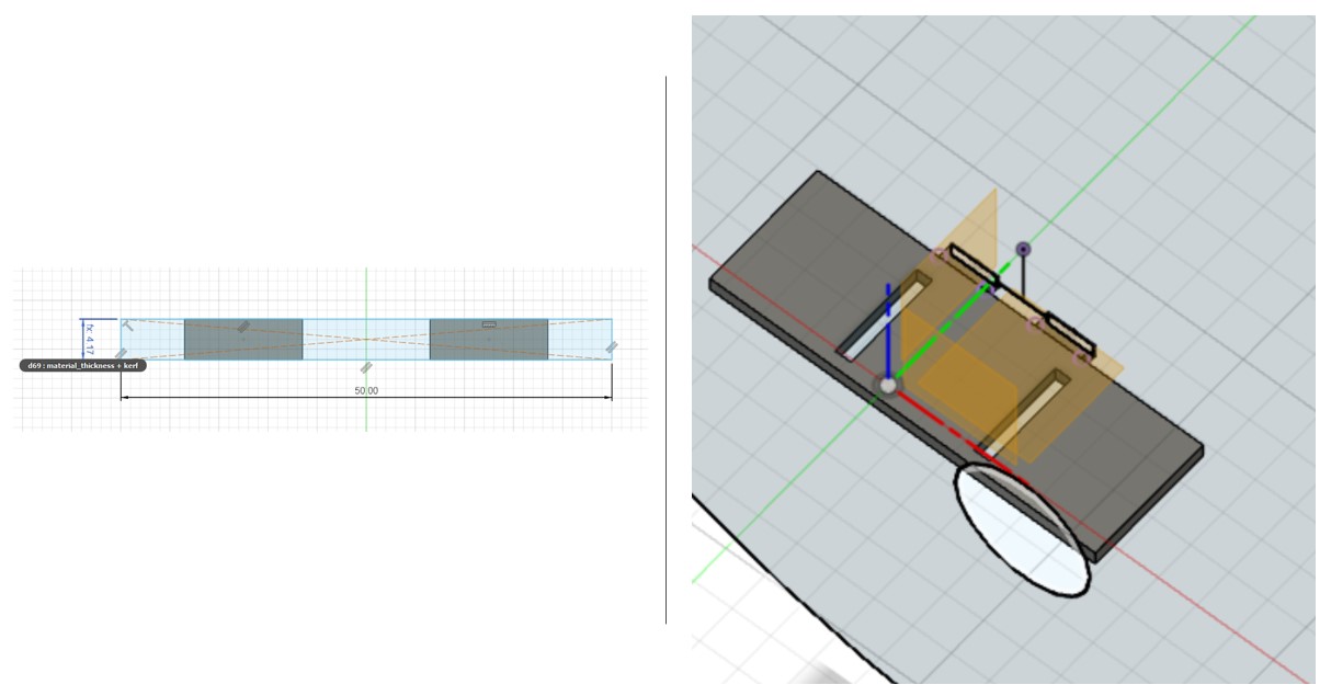
The holder can be created by sketching a rectangle with the length equals to 100 mm and width equals to 4.17 mm, which should be extruded by 33 mm, same as the length of the motor.
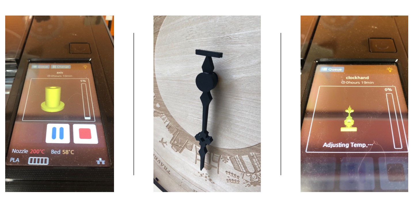
2.5 Clock hand and Axis
The clock hand was designed in CorelDraw and imported to Fusion 360 as a SVG file. Simply by combining and rotating basic common shapes, a relatively complex clock hand can be designed.
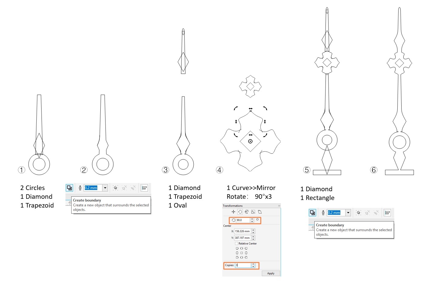
Saving the design as a SVG file and inserting it into Fusion 360 will allow it to be extruded for thickness. Before extruding the sketch, it is a great idea to check if there is any broken lines or less optimal lines and trim them.
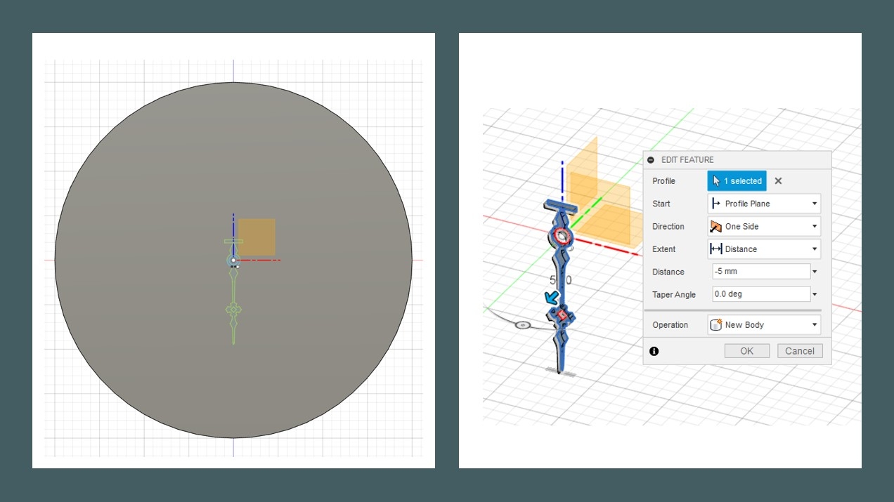
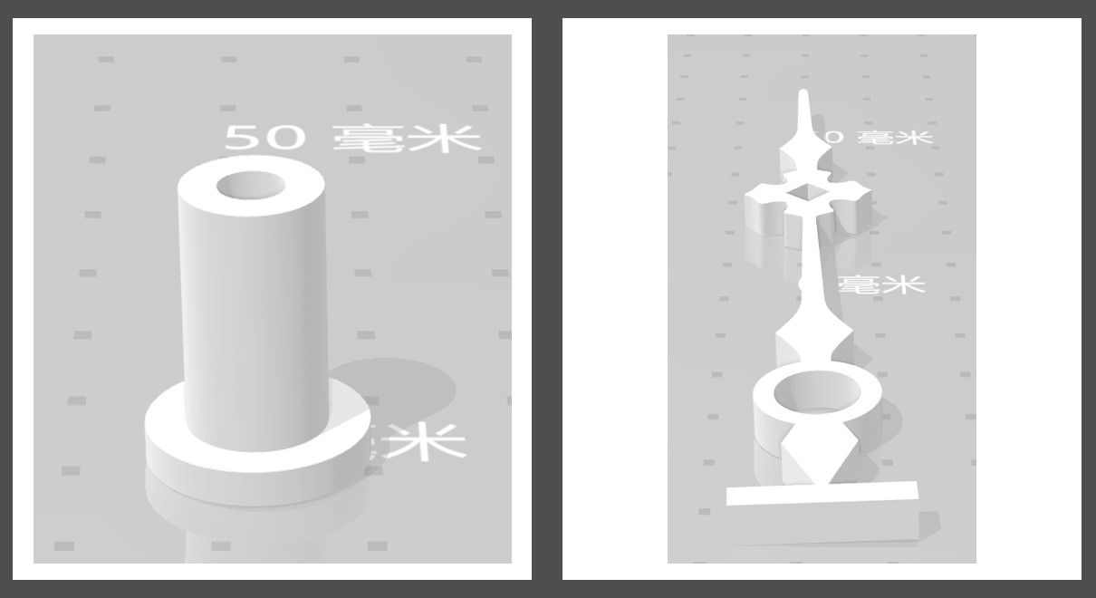
The major body of the axis is designed to be 10 mm, while on its back side, there is a pocket of diameter= 7.12mm, depth= 5mm reserved for the motor gear.
Both parts are 3D-printed.
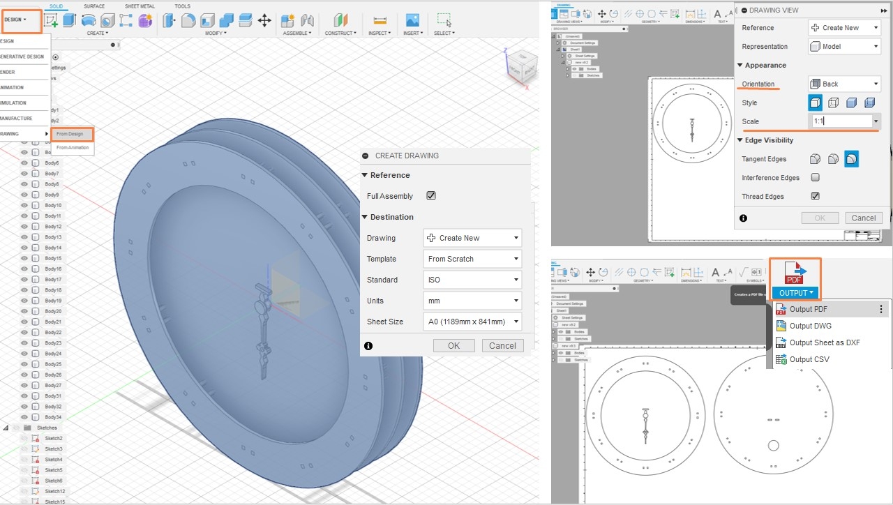
After designing the structure of the clock, the contour of the major parts should be exported as PDF for further decorations.
Design >> Drawing >> Creating Drawing from Design will allow the contour to be precisely exported.
2D Design
After importing the contours from the Fusion 360, the details and decorations are added to the board.
1. Halo Layer
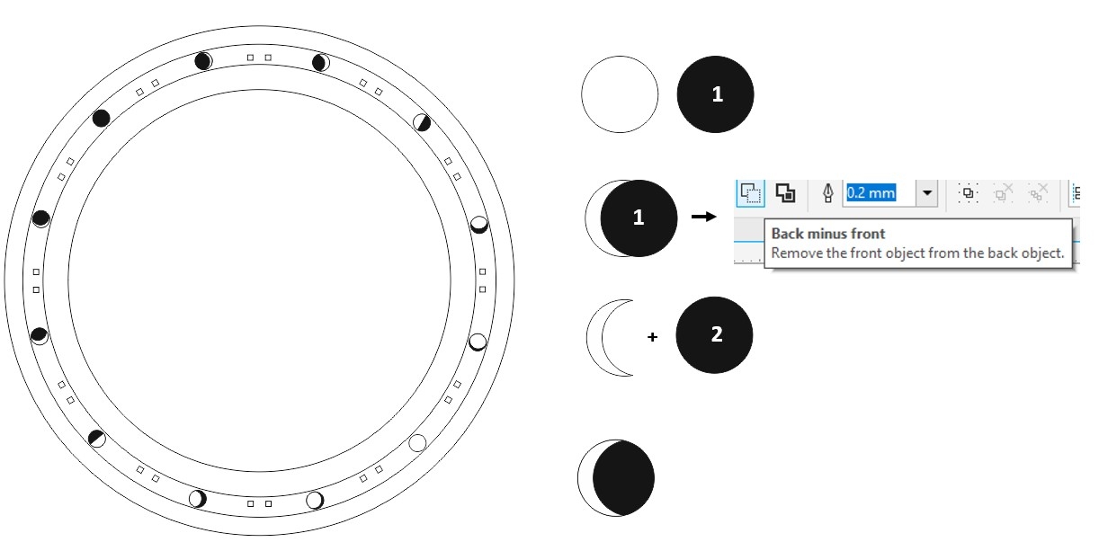
I decided to fill this layer with the lunar phase patterns, because it may reduce the obtrusiveness of the connection slots due to the combination of bright and dark elements.
The lunar phase can be created with easy boolean combination:
- Draw a bright circle and a dark circle
- Use the dark circle to cover parts of the bright circle and make the shape of the cresent or waxing phases
- Apply Boolean: Back minus Front
- Draw another dark circle and combine with the cresent/waxing shapes
The line width of the lines to be cut, as opposed to be engraved,are set to 0.02 mm.
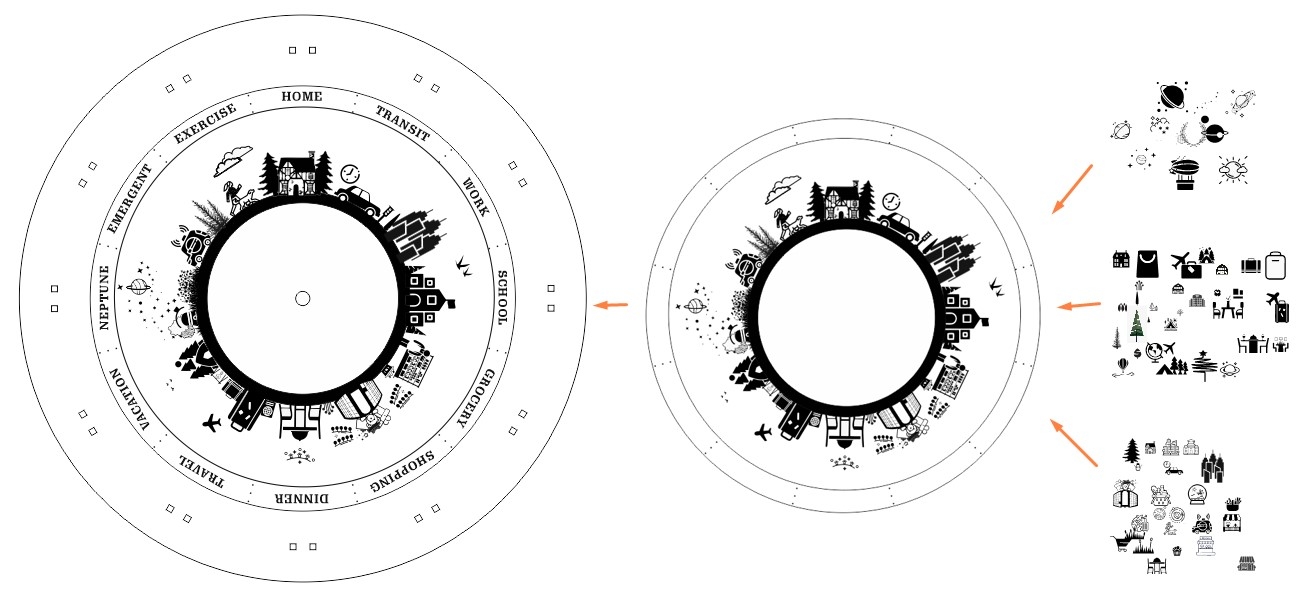
2 Main Layer, Clock Face
The clock face was divided into 12 sections that correspond to the 12 defined locations. I have collected many free SVG icons from websites like SVG Repo and The Noun Project.
In this design, I was trying to add some story lines by adding patterns and elements that can connect the different scenarios, which should blur the boundaries and smooth the transition between different locations.
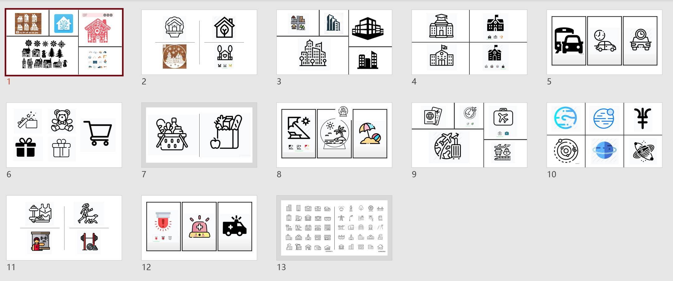
Based on the free SVG files, I have created the icons for each location. Some locations have multiple potential designs for selection. The line width of the lines to be cut, as opposed to be engraved,are set to 0.02 mm.
3.3 Backboard and Connection Parts
The backboard and connection parts do not need much decoration. The only necessary change is to set the lines to be cut to 0.02 mm wide.
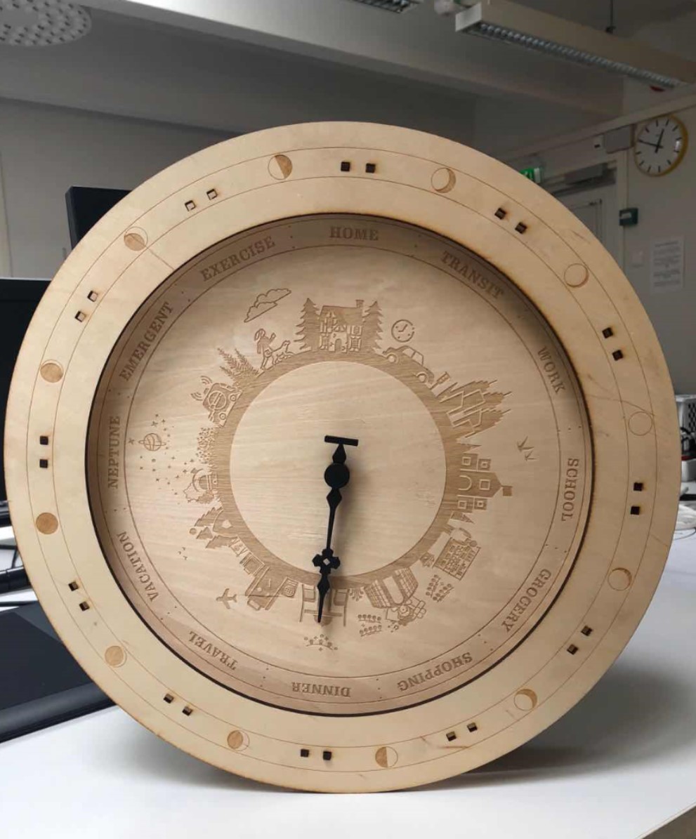
The expected appreance of the clock from the front view should be like this.
ELectronic Design
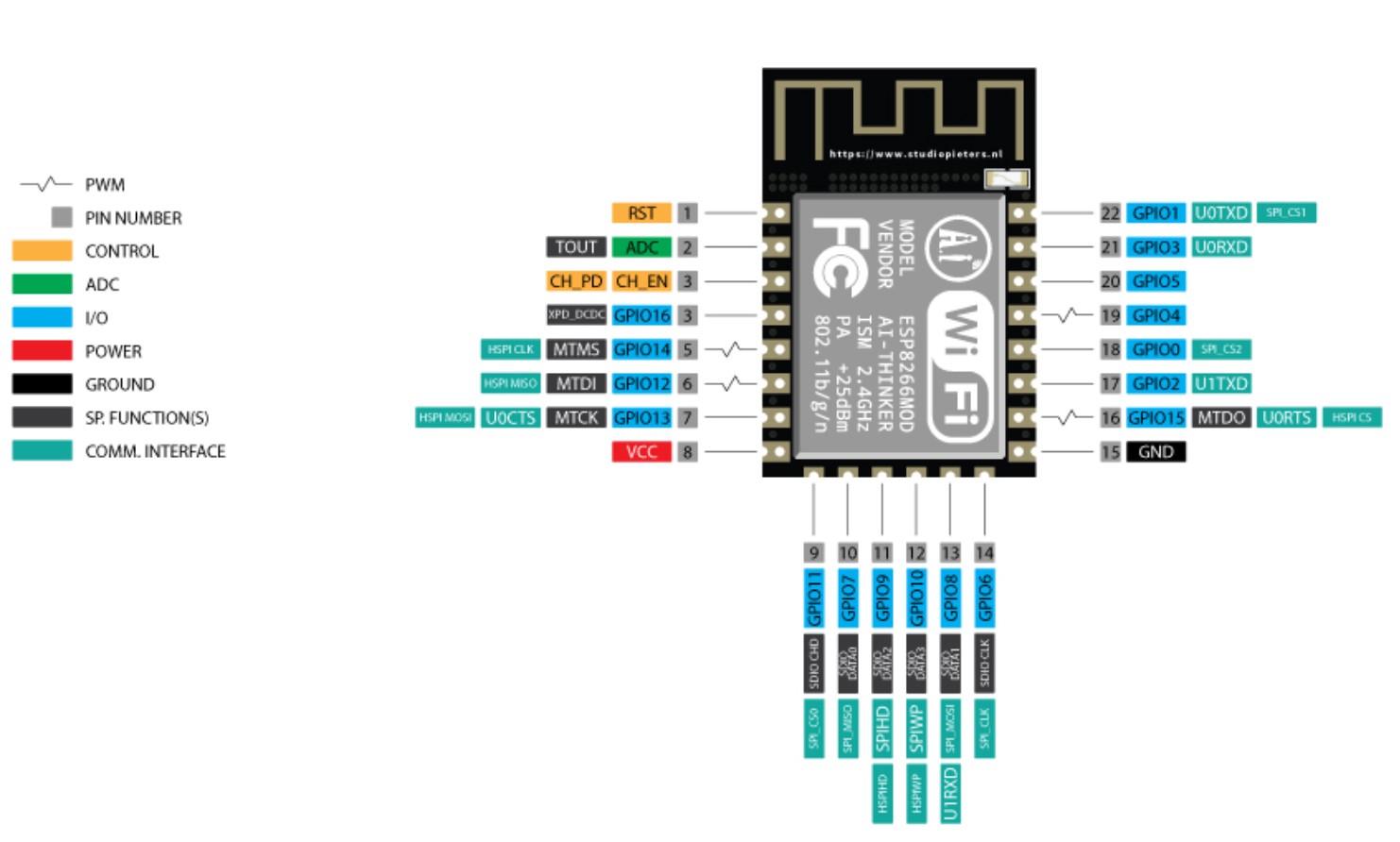
ESP8266
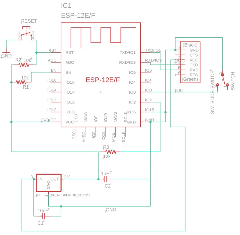
An ESP8266 12F Module was used to received the signal pushed from Adafruit via Wi-Fi.
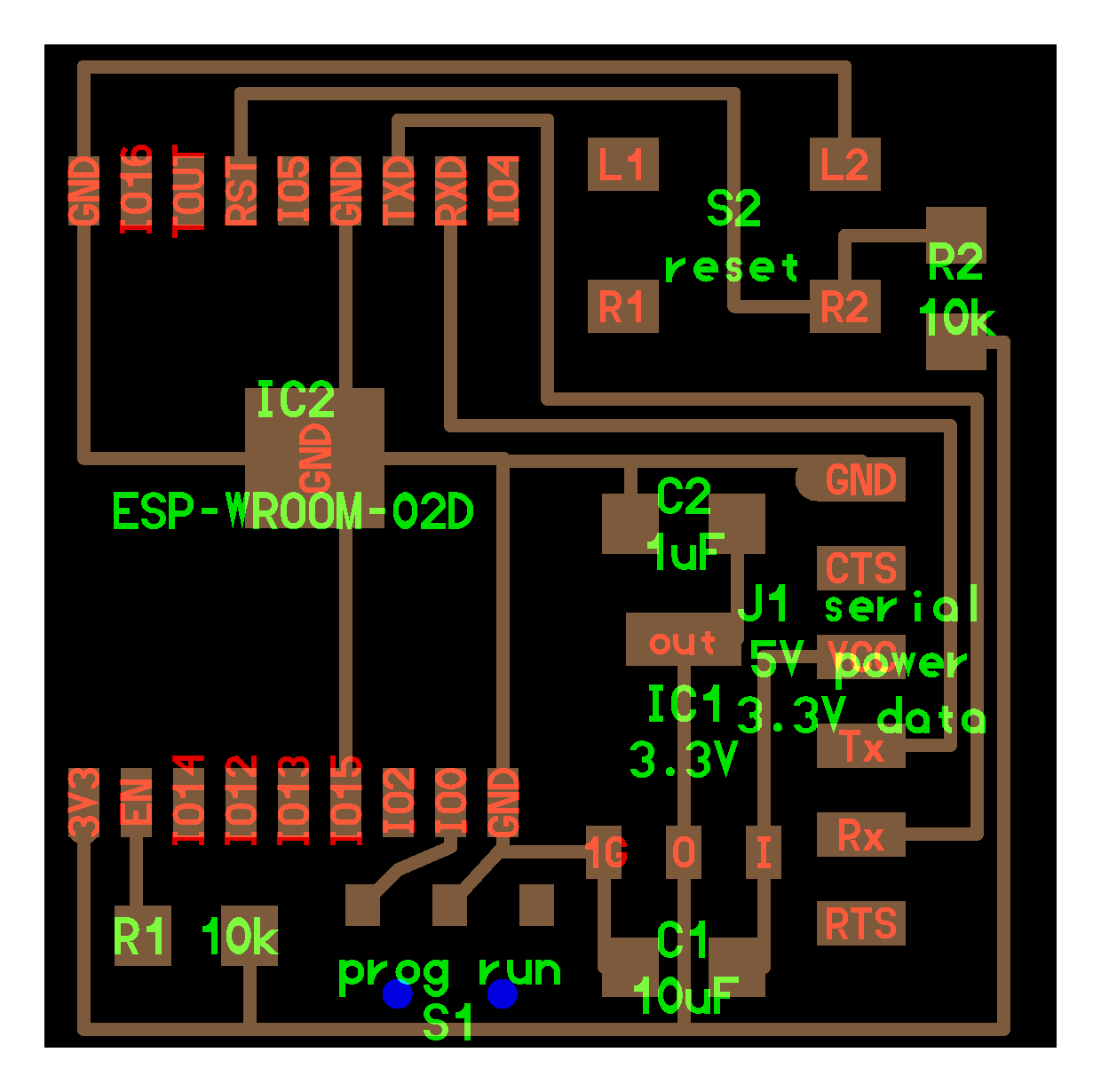
My design of ESP8266 board was derived from Neil's design of ESP-WROOM-02D board. The components used for this board include:
-ESP8266-12F Wi-Fi Module
-10k resistor x 2
-12k resistor
-1uF capacitor
-10uF capacitor
-MOSFET SOT223 Regulator(3.3V)
-button switch
-slide switch
-6-pin FTDI connector

credit
For ESP8266 12f module, pin GPIO0,GPIO2, and GPIO15 requires special attention, because these pins determine what mode the chip starts up in. Based on this tutorial, for normal program execution, the following connections are necessary:
GPIO0 -> VCC(3.3V)
GPIO2 -> VCC(3.3V)
GPIO15 -> GND
The others pins can follow the identical strategies as Neil's ESP-WROOM-02D design.
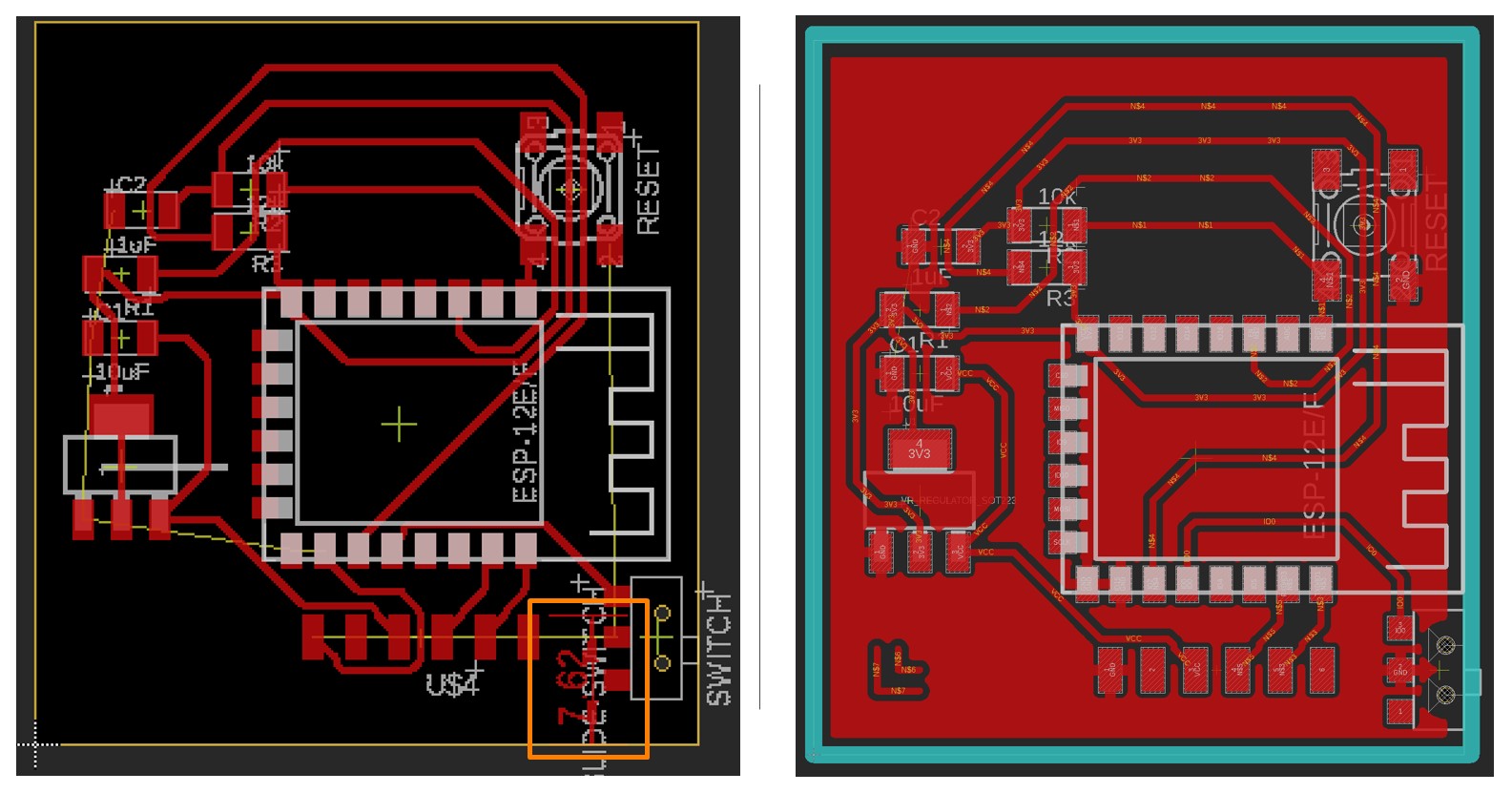
From the ESP8266 Schematics, the board layout can be arranged. One noteworthy detail is that a 7.62 mm distance should be left between the board edge and the 6-pin FTDI connector.
In most of cases, the antenna of ESP8266 should be out of the board for better connection. I kept the antenna on the board mainly because I need the space underneath it for wiring.
ATtiny 1614
An ATTiny 1614 chip is used as the microcontroller.
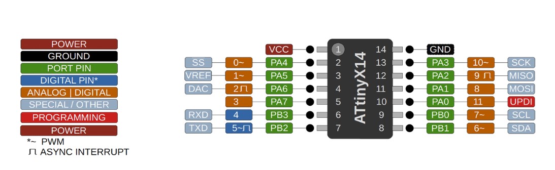
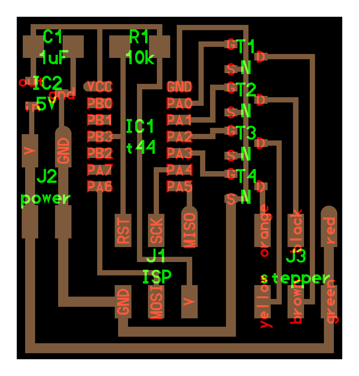
The design of my ATtiny 1614 board derived from Neil's design of ATtiny44 board that used to control unipolar stepper motor. Besides the 4 pins that connected to the transitors that controls the stepper motor, based on the suggestions of our instructors Ivan and Antti, I have used 3 additional pins for hall effect sensor and other potential usage.
The components used for this board include:
- ATtiny 1614 chip
- MOSFET_SOT223 Regulator(5V)
- MOSFET_NSOT23 Transitor x 4
- 1uF capacitor
- 10uF capacitor
- 3 pin SMD_RA_FEMALE connector
- 2X2-PINHEAD-SMD x 4
- 2X3-PINHEAD-SMD
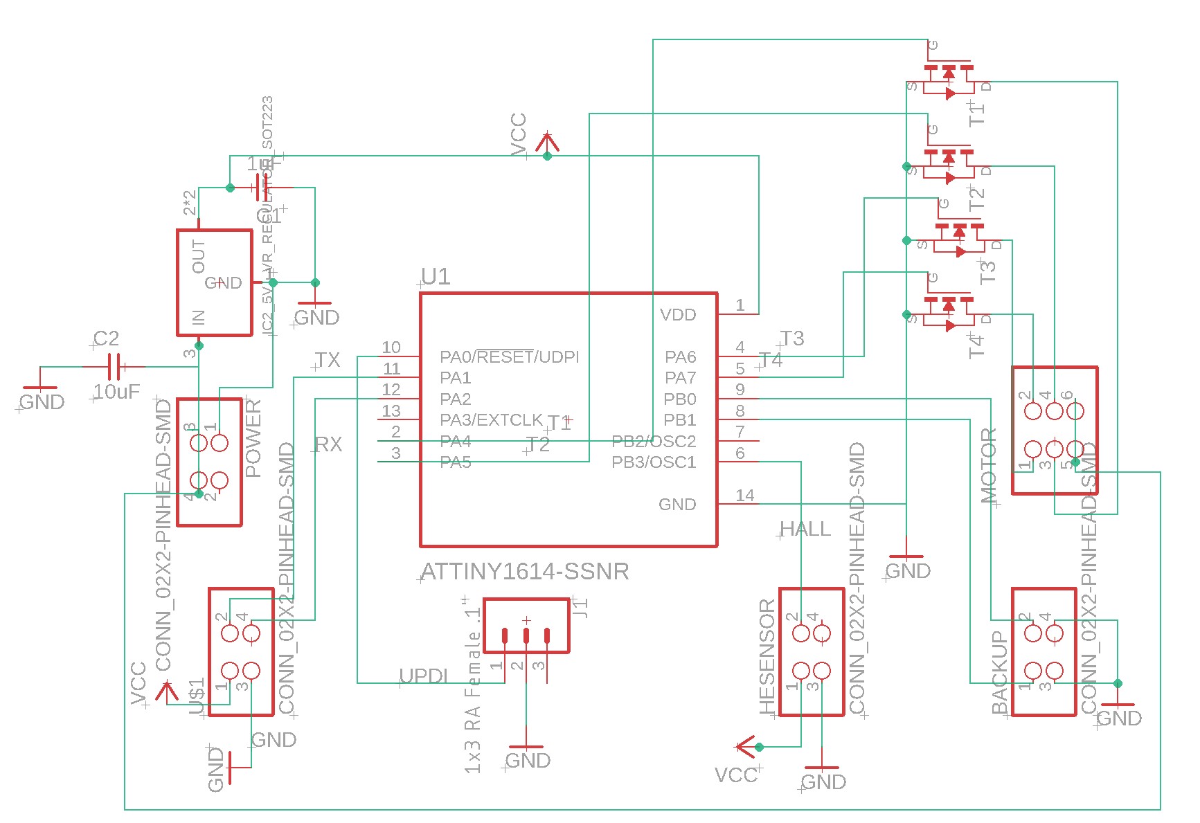
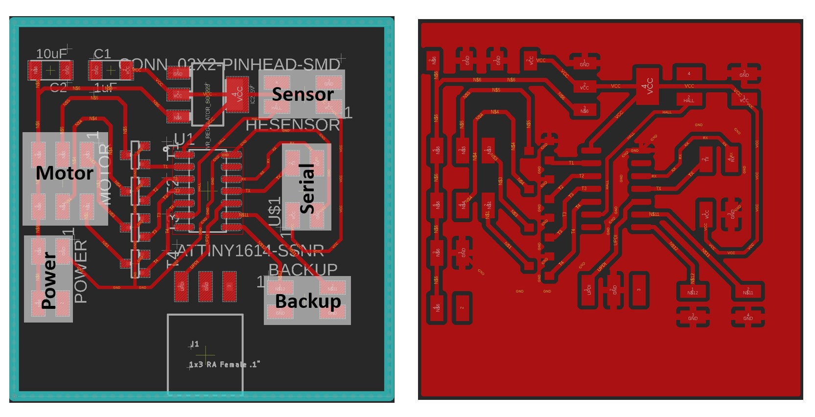
There is one thing noteworthy when wiring the components: the GND line underneath the 4 transitors should be set to 13~14 mil instead of the commonly used 16 mil. Otherwise, the line will too broad for the transistors and hence cannot be drawn.
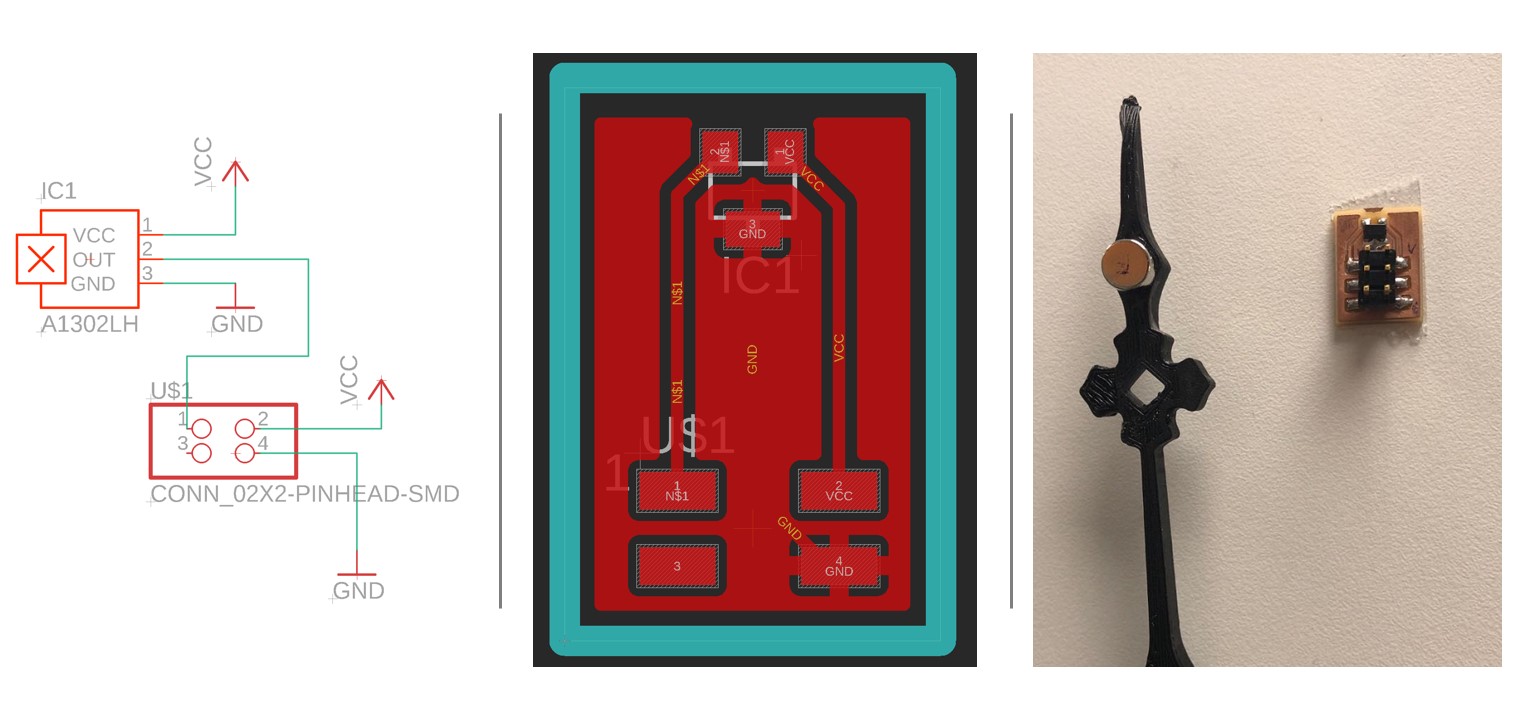
Hall Effect Sensor
A Hall Effect sensor is used to set the zero point of the motor moving path. The sensor is fixed on the back of the middle layer of the clock at the 12 o'clock position. A strong magnet is attached to the back of the clock hand, and when never it passes the sensor, it will send a signal to ATtiny 1614 and set the position as zero point.
The components used for this board include:
-SOT23-W Hall Effect Sensor
- 2X2-PINHEAD-SMD
Prototyping
In the prototyping stage, the designs are cut, printed, milled, soldered, assembled, and connected, while codes are written, uploaded, and tested. This is the stage where all the pieces of design integrate and work as a system.
Laser Cutting
The clock body is laser cut with 4mm Plywood using the Epilog Laser Fusion laser cutter. A common issue of 4mm Plywood is that it frequently bends and sometimes hence make the parts mismatch with each other. Thus, it maybe a good idea to use heavy metal pieces to press the board.
The detailed operation procedure can be found in Week 3 document.
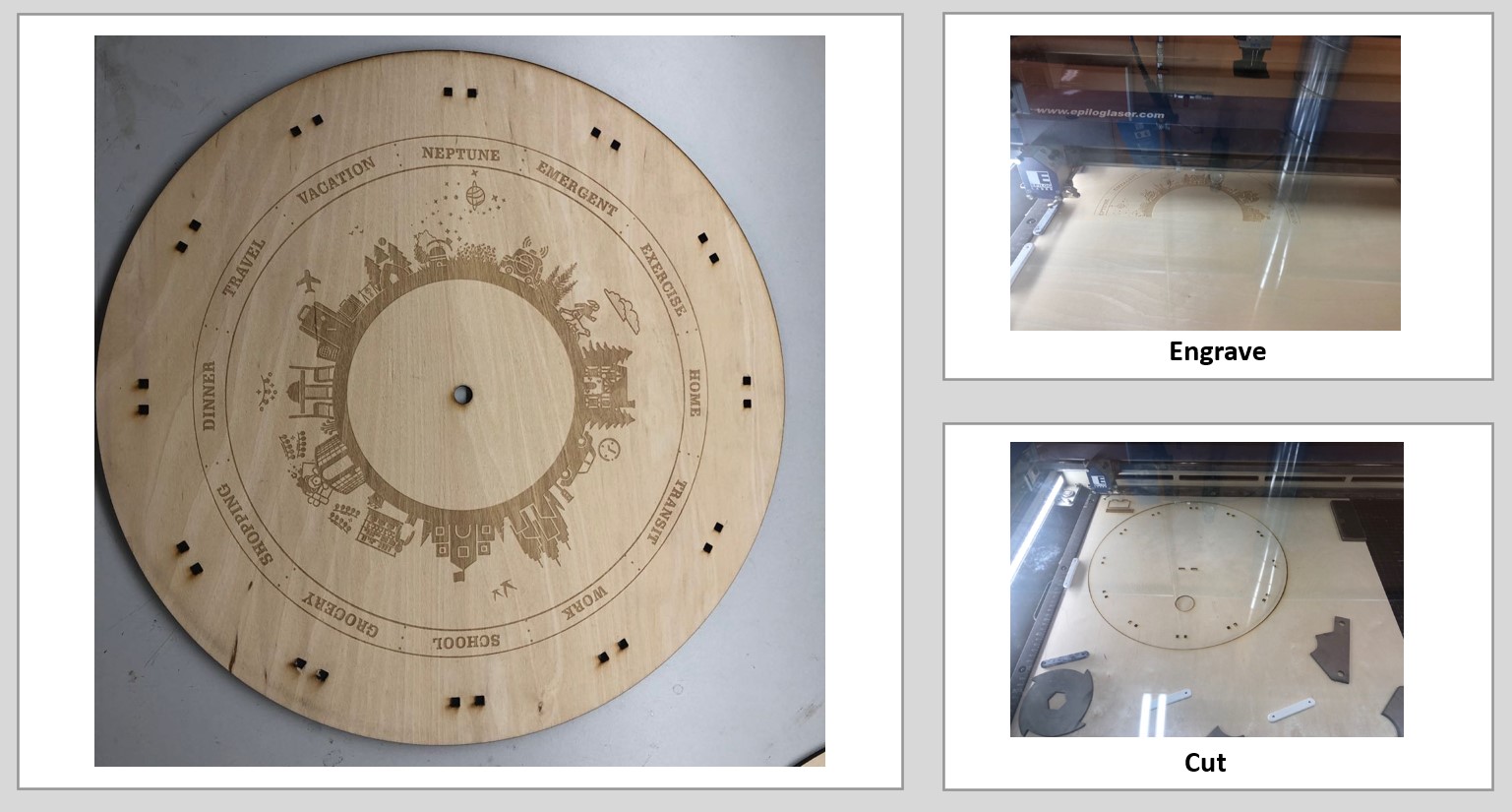
Comparing to 3mm MDF, the engraved patterns on 4mm Plywood tend to have a lighter color and the cut edge also burnt less, which is one of the reasons for me to use 4mm Plywood.
3D Printing
I used the Sindoh DWOX DP200 3D printer to print the clock hand and axis because this printer print quite efficiently with adequately good precision.
The operation interface are very straightforward and user-friendly.After load the file, simply following Slice >> Setting >> Support Placement: Touching Buildplate >> Print procedure will initiate the printing process.
PCB Board Milling
The first step of miling is to transform the PNG files into milling path rml files. The monochrome PNG files of the top layer and milling layer of the board design are respectively from Autodesk Eagle exported with resolution of 2400 px.
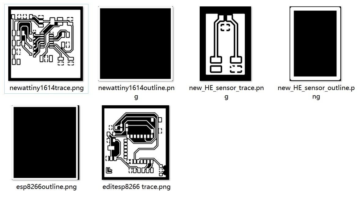
The PNG files should then be uploaded to the online processor mods for RML files.
-Setting up Mods
- Right Click >> Programs >> Open Server Program >>SRM-20 >>PCB png
- Delete "WebSocket Device" module >> Right click >> modules >> open server modules >> file >> save.
-Generate trace image
- Upload the board image without inverting
- Mill trace (1/64)>>tool diameter=0.4mm>>offset number=4
-Generate outline image
- Upload the outline image and invert
-Mill Outline(1/32))>>tool diameter=1 mm>>offset number=1
-Calculate and save the rml file.
A Roland SRM-20 milling machine is used for this task, the detailed operation procedures can be found in Week 4 document.

Embedded Programming
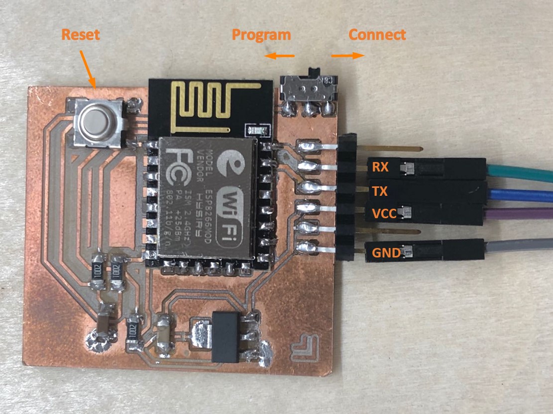
ESP8266
The ESP8266 board is best to be programmed with FTDI cable. During programming, the switch needs to be slided to the programming position, which is the side close to the ESP8266 module on my board.
The code I used for ESP8266 was developed by our instructor Iván in his tutorial.
In brief, this period of code accomplish these tasks:
1. Setting up connection between ESP8266 and Adafruit IO with the information in config.h
2. Setting up the feed
- AdafruitIO_Feed *feedX = io.feed("XXX");
3. A handleMessage function will be called whenever a message is received from adafruit io.
* Each feed should has its own handleMessage function
void handleMessage【X】(AdafruitIO_Data *data) {
// When received a position
Serial.println("【X】");//location
digitalWrite (LED, LOW); // Making LED High.
delay(500); // Some Delay
digitalWrite (LED, HIGH); // Making LED LOW.
}
4. For each feed, using get() function to resending the last value for this feed
"Because Adafruit IO doesn't support the MQTT retain flag, get() function can be used to ask IO to resend the last value for this feed to just this MQTT client after the io client is connected."--Ivan
5.Output the received information.
The original code uses serial print to indicate the connection status and received feed.
However, as the ESP8266 is connected to the ATtiny 1614 board during actual usage, the serial print will not be available and hence cannot convey the information. Therefore, I used the LEDs to indicate the status instead.
- The built-in LED of ESP8266 12f module is controlled by Pin2.
- In this case, LED on = LOW, LED off=HIGH
The code are posted below and can be download from the file section.
Adafruit_IFTTT_location
// Adafruit IO Subscription Example

                //

                // Adafruit invests time and resources providing this open source code.

                // Please support Adafruit and open source hardware by purchasing

                // products from Adafruit!

                //

                // Written by Todd Treece for Adafru
it Industries

                // Copyright (c) 2016 Adafruit Industries

                // Licensed under the MIT license.

                //

                // All text above must be included in any redistribution.


                /*

                  Code written by Iván Sánchez Milara based on example code adafruitio_01_subscribe

                  Tutorials:

                    - https://learn.adafruit.com/using-ifttt-with-adafruit-io/

                    - https://learn.adafruit.com/adafruit-io-basics-esp8266-arduino/


                  This example code is in public domain.

                 *************************************************************

                  This example runs directly on NodeMCU.

                  Note: This requires ESP8266 support package:

                    https://github.com/esp8266/Arduino

                And the following libraries:

                  - Adafruit IO Arduino

                  - Adafruit MQTT library

                 *************************************************************/


                #include <ESP8266WiFi.h>

                /************************** Configuration ***********************************/

                //const int LED = 2;

                // edit the config.h tab and enter your Adafruit IO credentials

                // and any additional configuration needed for WiFi, cellular,

                // or ethernet clients.

                #include "config.h"


                // set up the feed

                AdafruitIO_Feed *feed0 = io.feed("Home");

                AdafruitIO_Feed *feed1 = io.feed("Commute");

                AdafruitIO_Feed *feed2 = io.feed("Work");

                AdafruitIO_Feed *feed3 = io.feed("School");

                AdafruitIO_Feed *feed4 = io.feed("Grocery");

                AdafruitIO_Feed *feed5 = io.feed("Shopping");

                AdafruitIO_Feed *feed6 = io.feed("Dinner");

                AdafruitIO_Feed *feed7 = io.feed("Travel");

                AdafruitIO_Feed *feed8 = io.feed("Vacation");

                AdafruitIO_Feed *feed9 = io.feed("Neptune");

                AdafruitIO_Feed *feed10 = io.feed("Emergent");

                AdafruitIO_Feed *feed11 = io.feed("Exercise");


                #define delay_time 500

                const int LED=2;


                void setup()

                {


                   pinMode (LED, OUTPUT);

                  // start the serial connection

                  Serial.begin(9600);


                  // wait for serial monitor to open

                  while(! Serial);


                  //Serial.print("Connecting to Adafruit IO");


                  // start MQTT connection to io.adafruit.com

                  io.connect();


                  // set up a message handler for the count feed.

                  // the handleMessage function (defined below)

                  // will be called whenever a message is

                  // received from adafruit io.

                  feed0->onMessage(handleMessage0);

                  feed1->onMessage(handleMessage1);

                  feed2->onMessage(handleMessage2);

                  feed3->onMessage(handleMessage3);

                  feed4->onMessage(handleMessage4);

                  feed5->onMessage(handleMessage5);

                  feed6->onMessage(handleMessage6);

                  feed7->onMessage(handleMessage7);

                  feed8->onMessage(handleMessage8);

                  feed9->onMessage(handleMessage9);

                  feed10->onMessage(handleMessage10);

                  feed11->onMessage(handleMessage11);


                  // wait for an MQTT connection

                  // NOTE: when blending the HTTP and MQTT API, always use the mqttStatus

                  // method to check on MQTT connection status specifically

                 // while(io.mqttStatus() < AIO_CONNECTED) {

                    //Serial.print(".");

                    digitalWrite (LED, HIGH); // Making LED High.

                    delay(500);              // Some Delay

                    digitalWrite (LED, LOW);  // Making LED LOW.

                    delay(500);

                    //delay(500);


                 // }


                  // Because Adafruit IO doesn't support the MQTT retain flag, we can use the

                  // get() function to ask IO to resend the last value for this feed to just

                  // this MQTT client after the io client is connected.

                  feed0->get();

                  feed1->get();

                  feed2->get();

                  feed3->get();

                  feed4->get();

                  feed5->get();

                  feed6->get();

                  feed7->get();

                  feed8->get();

                  feed9->get();

                  feed10->get();

                  feed11->get();


                  // we are connected

                  //Serial.println();

                  //Serial.println(io.statusText());

                  digitalWrite (LED, LOW); // Making LED High.


                }


                void loop()

                {


                  // io.run(); is required for all sketches.

                  // it should always be present at the top of your loop

                  // function. it keeps the client connected to

                  // io.adafruit.com, and processes any incoming data.

                  io.run();


                  // Because this sketch isn't publishing, we don't need

                  // a delay() in the main program loop.


                }


                // this function is called whenever a 'feed' message

                // is received from Adafruit IO. it was attached to

                // the counter feed in the setup() function above.

                void handleMessage0(AdafruitIO_Data *data) {

                 // When received a position

                  Serial.println("0");//home

                  digitalWrite (LED, LOW); // Making LED High.

                  delay(500);              // Some Delay

                  digitalWrite (LED, HIGH);  // Making LED LOW.


                }

                void handleMessage1(AdafruitIO_Data *data) {

                 // When received a position

                  Serial.println("1");//commute

                  digitalWrite (LED, LOW); // Making LED High.

                  delay(500);              // Some Delay

                  digitalWrite (LED, HIGH);  // Making LED LOW.


                }

                void handleMessage2(AdafruitIO_Data *data) {

                 // When received a position

                  Serial.println("2");//work

                  digitalWrite (LED, LOW); // Making LED High.

                  delay(500);              // Some Delay

                  digitalWrite (LED, HIGH);  // Making LED LOW.


                }

                void handleMessage3(AdafruitIO_Data *data) {

                 // When received a position

                  Serial.println("3"); //school

                  digitalWrite (LED, LOW); // Making LED High.

                  delay(500);              // Some Delay

                  digitalWrite (LED, HIGH);  // Making LED LOW.


                }

                void handleMessage4(AdafruitIO_Data *data) {

                 // When received a position

                  Serial.println("4");//grocery

                  digitalWrite (LED, LOW); // Making LED High.

                  delay(500);              // Some Delay

                  digitalWrite (LED, HIGH);  // Making LED LOW.


                }

                void handleMessage5(AdafruitIO_Data *data) {

                 // When received a position

                  Serial.println("5");//shopping

                  digitalWrite (LED, LOW); // Making LED High.

                  delay(500);              // Some Delay

                  digitalWrite (LED, HIGH);  // Making LED LOW.


                }

                void handleMessage6(AdafruitIO_Data *data) {

                 // When received a position

                  Serial.println("6");//dinner

                  digitalWrite (LED, LOW); // Making LED High.

                  delay(500);              // Some Delay

                  digitalWrite (LED, HIGH);  // Making LED LOW.


                }

                void handleMessage7(AdafruitIO_Data *data) {

                 // When received a position

                  Serial.println("7");//travel

                  digitalWrite (LED, LOW); // Making LED High.

                  delay(500);              // Some Delay

                  digitalWrite (LED, HIGH);  // Making LED LOW.


                }

                void handleMessage8(AdafruitIO_Data *data) {

                 // When received a position

                  Serial.println("8");//vacation

                  digitalWrite (LED, LOW); // Making LED High.

                  delay(500);              // Some Delay

                  digitalWrite (LED, HIGH);  // Making LED LOW.


                }

                void handleMessage9(AdafruitIO_Data *data) {

                 // When received a position

                  Serial.println("9");//Neptune

                  digitalWrite (LED, LOW); // Making LED High.

                  delay(500);              // Some Delay

                  digitalWrite (LED, HIGH);  // Making LED LOW.


                }

                void handleMessage10(AdafruitIO_Data *data) {

                 // When received a position

                  Serial.println("10");//emergent

                  digitalWrite (LED, LOW); // Making LED High.

                  delay(500);              // Some Delay

                  digitalWrite (LED, HIGH);  // Making LED LOW.


                }

                void handleMessage11(AdafruitIO_Data *data) {

                 // When received a position

                  Serial.println("11");//exercise

                  digitalWrite (LED, LOW); // Making LED High.

                  delay(500);              // Some Delay

                  digitalWrite (LED, HIGH);  // Making LED LOW.


                }
config.h
                    /************************ Adafruit IO Config *******************************/


                    // visit io.adafruit.com if you need to create an account,

                    // or if you need your Adafruit IO key.

                    #define IO_USERNAME [replace with your own user name]

                    #define IO_KEY [replace with your own user name]


                    // Add the name of the feed you want to connect to


                    //#define IO_FEED_NAME "Home"


                    /******************************* WIFI **************************************/


                    // the AdafruitIO_WiFi client will work with the following boards:

                    //   - HUZZAH ESP8266 Breakout -> https://www.adafruit.com/products/2471

                    //   - Feather HUZZAH ESP8266 -> https://www.adafruit.com/products/2821

                    //   - Feather HUZZAH ESP32 -> https://www.adafruit.com/product/3405

                    //   - Feather M0 WiFi -> https://www.adafruit.com/products/3010

                    //   - Feather WICED -> https://www.adafruit.com/products/3056

                    //   - Adafruit PyPortal -> https://www.adafruit.com/product/4116

                    //   - Adafruit Metro M4 Express AirLift Lite ->

                    //   https://www.adafruit.com/product/4000

                    //   - Adafruit AirLift Breakout -> https://www.adafruit.com/product/4201

                    //   - Adafruit AirLift Shield -> https://www.adafruit.com/product/4285

                    //   - Adafruit AirLift FeatherWing -> https://www.adafruit.com/product/4264


                    #define WIFI_SSID [replace with your own Wi-Fi SSID]

                    #define WIFI_PASS [replace with your own Wi-Fi Password
]


                    // uncomment the following line if you are using airlift

                    // #define USE_AIRLIFT


                    // uncomment the following line if you are using winc1500

                    // #define USE_WINC1500


                    // comment out the following lines if you are using fona or ethernet

                    #include "AdafruitIO_WiFi.h"


                    #if defined(USE_AIRLIFT) || defined(ADAFRUIT_METRO_M4_AIRLIFT_LITE) ||
      \
                        defined(ADAFRUIT_PYPORTAL)

                    // Configure the pins used for the ESP32 connection

                    #if !defined(SPIWIFI_SS) // if the wifi definition isnt in the board variant

                    // Don't change the names of these #define's! they match the variant ones

                    #define SPIWIFI SPI

                    #define SPIWIFI_SS 10 // Chip select pin

                    #define NINA_ACK 9    // a.k.a BUSY or READY pin

                    #define NINA_RESETN 6 // Reset pin

                    #define NINA_GPIO0 -1 // Not connected

                    #endif
                    AdafruitIO_WiFi io(IO_USERNAME, IO_KEY, WIFI_SSID, WIFI_PASS, SPIWIFI_SS,

                                       NINA_ACK, NINA_RESETN, NINA_GPIO0, &SPIWIFI);

                    #else

                    AdafruitIO_WiFi io(IO_USERNAME, IO_KEY, WIFI_SSID, WIFI_PASS);

                    #endif

                    /******************************* FONA **************************************/


                    // the AdafruitIO_FONA client will work with the following boards:

                    //   - Feather 32u4 FONA -> https://www.adafruit.com/product/3027


                    // uncomment the following two lines for 32u4 FONA,

                    // and comment out the AdafruitIO_WiFi client in the WIFI section

                    // #include "AdafruitIO_FONA.h"

                    // AdafruitIO_FONA io(IO_USERNAME, IO_KEY);


                    /**************************** ETHERNET ************************************/


                    // the AdafruitIO_Ethernet client will work with the following boards:

                    //   - Ethernet FeatherWing -> https://www.adafruit.com/products/3201


                    // uncomment the following two lines for ethernet,

                    // and comment out the AdafruitIO_WiFi client in the WIFI section

                    // #include "AdafruitIO_Ethernet.h"

                    // AdafruitIO_Ethernet io(IO_USERNAME, IO_KEY);
After the code is successfully uploaded, turn the slide switch to the connect position and press the reset button, then the ESP8266 board is ready to be used.
ATtiny 1614
The ATtiny 1614 board needs to accomplish several crucial tasks:
A. Control the unipolar stepper motor
B. Connect to external power supply
C. Receiving signals from Hall Effect Sensor
D. Power ESP8266 and maintain serial communication
E. Control the LED light for Emergenct status (NOT included in this prototype but pins reserved)
A. Motor Control
A Jameco 35BY48L030-01 Unipolar Stepper Motor is used to move the clock hand.
Some specifications from the datasheet that are related to my project
-Rated voltage: 7 volts DC
-Step angle (°5%): 7.5°
-Current: 350 mA
-Shaft diameter: 0.078"
-Shaft length: 0.47"
-Motor diameter: 1.378"
-Motor depth: 0.866" max.
As shown in the picture above, by activating the magnets in the correct order via corresponding coils, the motor can turn clockwise or counterclockwise by any designated steps. Thus, in my case, controlling the motor with ATtiny 1614 requires the following procedures.
1. Determine the Coil-Lead mapping
The Jameco Motor I used have 5 leads: Black, Blue, Orange, Red, Yellow.
According to the datasheet, the blue and red leads are on the same coil, while black and yellow leads are on the other coil. Orange lead is the power line.
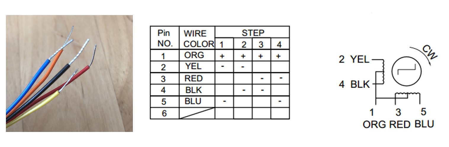
2. Determine the sequence of activation
The activation sequence of this motor to move in clockwise direction has been Yellow/Red-Red/Black-Black/Blue-Blue/Yellow, which is hinted by the Pin No. column is the figure above.
* The hint may not be quite obvious at first, because it does not quite align with the "step" columns. Using the oscilloscope to test the voltage of each lead is a great idea when the datasheet is confusing
Because the 4 leads are controlled by 4 ATtiny 1614 pins via 4 transitors, the activation sequence can be translated into pin status as below:
            STEP 1: Yellow-HIGH; Red-HIGH; Black-LOW; Blue-LOW;

            STEP 2: Yellow-LOW; Red-HIGH; Black-HIGH; Blue-LOW;

            STEP 3: Yellow-LOW; Red-LOW; Black-HIGH; Blue-HIGH;

            STEP 4: Yellow-HIGH; Red-LOW; Black-LOW; Blue-HIGH;
3. Determine the Lead-Pin mapping
I did not find a great way to determine the lead-pin mapping other than simply try all combinations, especially when the sequence of activation is not clear.
*If the lead-pin mapping and activation sequence happen to mismatch the same way, the motor can still rotate clockwise as normal, but the mismatch will impose huge challenge in the following steps.
In my case, based on the activation sequence above, the Lead-Pin mappings are:
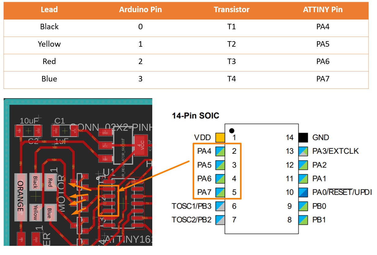
When programming in Arduino IDE, the Arduino Pin number should be used when define the pins.
                    const int T1_Black = 0;

                    const int T2_Yellow = 1;

                    const int T3_Red = 2;

                    const int T4_Blue = 3;
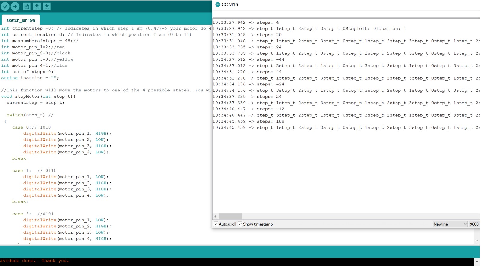
4. Programming
The logic of the motor control code are derived from this tutorial.In brief, this code allows the stepper motor to move between designate positions by counting steps.
This code contains three major sections:
-stepMotor(int step) function that defines the activation sequence of the motor coils
-step(int steps_to_move) function that defines the algorithm of the motor to move between positions.
A maximum step, which is the number of steps for a full revolution, is used as the reference to control the moving direction of the motor.
-moveToLocation(int location) function that gets the serial print from the serial input and determines the steps to go
              Motor Control Code


                const int T4_Blue = 3;
                const int T1_Black = 0;
                const int T3_Red = 2;
                const int T2_Yellow = 1;
                const int maxnumberofsteps = 48;

                int currentstep = 0; // Indicates in which step I am (0,47)-> your motor do 48 steps in one rotation
                int current_location = 0; // Indicates in which position I am (0 to 11)
                int num_of_steps = 0;
                String inString = "";

                #define step_delay 500

                void stepMotor(int step_t) {
                   switch (step_t) //
                  {
                    case 0:
                    //Serial.println("Yellow/Red HIGH");
                       digitalWrite(T4_Blue, LOW);
                       digitalWrite(T1_Black, LOW);
                       digitalWrite(T3_Red, HIGH);
                       digitalWrite(T2_Yellow, HIGH);

                    break;

                    case 1:
                       digitalWrite(T1_Black, HIGH);
                       digitalWrite(T3_Red, HIGH);
                       digitalWrite(T2_Yellow, LOW);
                       digitalWrite(T4_Blue, LOW);

                    break;

                    case 2:
                       digitalWrite(T4_Blue, HIGH);
                       digitalWrite(T1_Black, HIGH);
                       digitalWrite(T3_Red, LOW);
                       digitalWrite(T2_Yellow, LOW);
                    break;

                    case 3:
                       digitalWrite(T4_Blue, HIGH);
                       digitalWrite(T1_Black, LOW);
                       digitalWrite(T3_Red, LOW);
                       digitalWrite(T2_Yellow, HIGH);
                    break;

                  }
                 // Serial.print("step_t ");
                  //Serial.print(step_t);
                 }

                // Move x steps (negative will move backwards)
                void step(int steps_to_move)
                {
                  int steps_left = abs(steps_to_move);  // how many steps to take

                  int direction = 0;

                  // determine direction based on whether steps_to_mode is + or -:

                  if (steps_to_move > 0) {
                    direction = 1;
                  }

                  if (steps_to_move < 0) {
                    direction  = 0;
                  }

                  // decrement the number of steps, moving one step each time:

                  while (steps_left > 0)

                  {

                    // increment or decrement the step number,

                    // depending on direction:

                    if (direction == 1)

                    {
                      currentstep++;

                      if (currentstep == maxnumberofsteps) {
                        currentstep = 0;
                      }
                    }
                    else // direction==0
                    {
                      if (currentstep == 0) {
                        currentstep = maxnumberofsteps;
                      }
                      currentstep--;
                    }
                    // decrement the steps left:
                    steps_left--;

                    // step the motor to step number 0, 1, ..., {3 or 10}
                    stepMotor(currentstep % 4);
                      //Serial.print("Stepleft: ");
                  //Serial.println(steps_left);
                  delay (step_delay);
                  }

                }

                //Move to position
                void moveToLocation(int location){
                  num_of_steps = (location - current_location)*4; // Each location is 30 degrees. You have then 4 steps per locations

                  current_location = location;
                 Serial.print("steps: ");
                 Serial.println(num_of_steps);
                  step (num_of_steps);
                  }


                void setup() {

                  pinMode(T4_Blue, OUTPUT);
                  pinMode(T1_Black, OUTPUT);
                  pinMode(T3_Red, OUTPUT);
                  pinMode(T2_Yellow, OUTPUT);
                  Serial.swap(1);
                  Serial.begin(9600);
                  step(5);


                  currentstep=0;
                }

                void loop() {

                // put your main code here, to run repeatedly:
                    //for location10, 11 and 12, which are more than 1 byte
                  while (Serial.available()>0) {
                   int inChar = Serial.read();
                    if (isDigit(inChar)) {
                      // convert the incoming byte to a char and add it to the string:
                      inString += (char)inChar;
                    }
                    // if you get a newline, print the string, then the string's value:
                    if (inChar == '\n') {
                      //Serial.print("Value:");
                      int location = inString.toInt();
                      //Serial.println(location);
                      //Serial.print("String: ");
                      //Serial.println(inString);
                      // clear the string for new input:

                      inString = "";//

                      Serial.print("location: ");
                      Serial.println(location);
                      moveToLocation(location);
                      //step(location);
                    }
                  }
                /*
                for (int i=0; i<=48; i++){ //It should do ¼

                Serial.println(i);

                stepMotor(i%4); //module result from 0 to 4

                delay(2000);

                Serial.println("Moving 12");
                step(12);
                delay (5000);
                Serial.println("Moving 24");
                step(24);
                delay(5000);
                Serial.println("Moving 48");
                step(48);
                delay(5000);

                Serial.println("location 3");
                moveToLocation(3);
                Serial.println(current_location);
                delay (5000);
                Serial.println("location 5");
                moveToLocation(5);
                Serial.println(current_location);
                delay(5000);
                Serial.println("location 11");
                moveToLocation(11);
                Serial.println(current_location);
                delay(5000);
                Serial.println("location 6");
                moveToLocation(6);
                Serial.println(current_location);
                delay(5000);*/

                }
              stepMotor()Function


              void stepMotor(int step_t) {
               switch (step_t) //
              {
                case 0:
                //Serial.println("Yellow/Red HIGH");
                   digitalWrite(T4_Blue, LOW);
                   digitalWrite(T1_Black, LOW);
                   digitalWrite(T3_Red, HIGH);
                   digitalWrite(T2_Yellow, HIGH);

                break;

                case 1:
                   digitalWrite(T1_Black, HIGH);
                   digitalWrite(T3_Red, HIGH);
                   digitalWrite(T2_Yellow, LOW);
                   digitalWrite(T4_Blue, LOW);

                break;

                case 2:
                   digitalWrite(T4_Blue, HIGH);
                   digitalWrite(T1_Black, HIGH);
                   digitalWrite(T3_Red, LOW);
                   digitalWrite(T2_Yellow, LOW);
                break;

                case 3:
                   digitalWrite(T4_Blue, HIGH);
                   digitalWrite(T1_Black, LOW);
                   digitalWrite(T3_Red, LOW);
                   digitalWrite(T2_Yellow, HIGH);
                break;

              }
             // Serial.print("step_t ");
              //Serial.print(step_t);
             }
              step()Function


              void step(int steps_to_move)
                {
                  int steps_left = abs(steps_to_move);  // how many steps to take

                  int direction = 0;

                  // determine direction based on whether steps_to_mode is + or -:

                  if (steps_to_move > 0) {
                    direction = 1;
                  }

                  if (steps_to_move < 0) {
                    direction  = 0;
                  }

                  // decrement the number of steps, moving one step each time:

                  while (steps_left > 0)

                  {

                    // increment or decrement the step number,

                    // depending on direction:

                    if (direction == 1)

                    {
                      currentstep++;

                      if (currentstep == maxnumberofsteps) {
                        currentstep = 0;
                      }
                    }
                    else // direction==0
                    {
                      if (currentstep == 0) {
                        currentstep = maxnumberofsteps;
                      }
                      currentstep--;
                    }
                    // decrement the steps left:
                    steps_left--;

                    // step the motor to step number 0, 1, ..., {3 or 10}
                    stepMotor(currentstep % 4);
                      //Serial.print("Stepleft: ");
                  //Serial.println(steps_left);
                  delay (step_delay);
                  }

                }
              moveToLocation()


              void moveToLocation(int location){
                  num_of_steps = (location - current_location)*4; // Each location is 30 degrees. You have then 4 steps per locations

                  current_location = location;
                 Serial.print("steps: ");
                 Serial.println(num_of_steps);
                  step (num_of_steps);
                  }
5. Test and Debug
The test and debug process has been mostly in coordinating the serial communication, ESP8266 internet connection, and the motor coil activation sequence. More details can be found on these pages: Week 8, Embedded Programming, Week 9- Input device, Week 11 - Output device, Week 14 Communication, and this rough trouble shooting page.
B. Power Supply
The power supply connector locates near the motor pins.
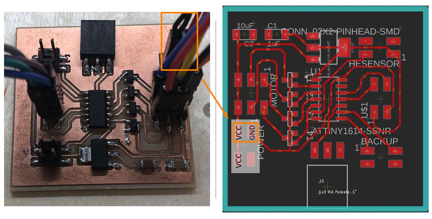
Both the ATtiny 1614 board and the ESP8266 board are powered by the VCC connector on ATtiny 1614 board through this connector, while they run with different voltage. It is highly recommended to double-check if the voltage at different locations are in these ranges:
- Motor VCC: 7V
- ATtiny1614 VCC: 5V
- ESP8266 VCC: 3.3V
C. Hall Effect Sensor Signal Reception
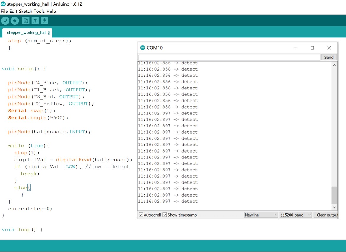
I used pin PB3 on ATtiny 1614 chip (Arduino IDE pin 4) to receive the signal from Hall Effect Sensor.The Hall Effect sensor can detect the magnetic field. I have positioned the Hall Effect Sensor on the 12-o'clock position on the back of the clock middle layer and sticked a strong magnet at the back of the clockhand.
Thus, when the clock is turned on, the clock hand starts to rotate until the hall effect sensor detects the magnetic field. When ATtiny 1614 receives the signal, the position will be set as the zero point.
The code related to Hall Effect Sensor is integrated into the ATtiny 1614 code, the full code can be found in the File section.For demonstrate purpose, only the code directly related to Hall Effect sensor are listed below.
                int currentstep = 0;

                //Hall Effect

                int hallsensor = 4;//pin PB3

                int digitalVal;//digital readings

                void setup() {

                    //...omited irrelevant code

                    pinMode(hallsensor,INPUT);


                      while (true){

                        step(1);

                        digitalVal = digitalRead(hallsensor);

                        if (digitalVal==LOW){ //low = detect

                          break;

                        }

                        else{

                          }

                      }

                      currentstep=0;

                    }
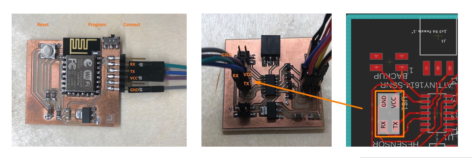
D.Serial Communication
First, the ESP8266 board and ATtiny 1614 board should have these pins connected:
●VCC - VCC
●GND - GND
●TX - TX
●RX - RX
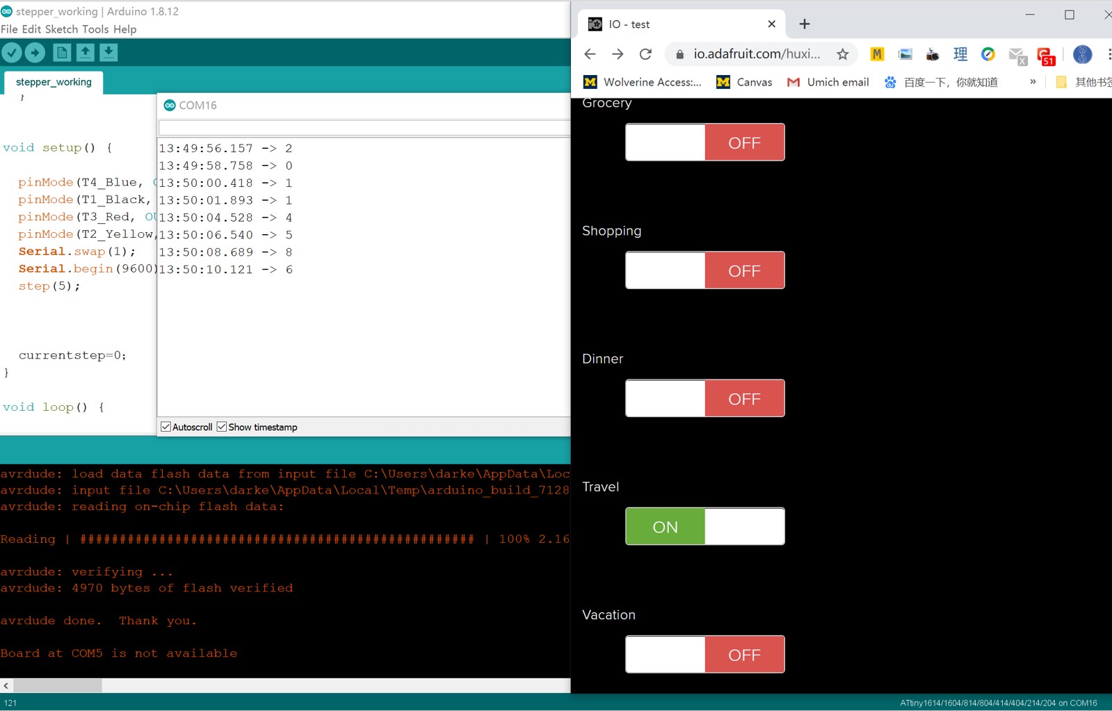
When the external power supply has been connected, ensure the slide switch is turned to the connection mode. In my case, it usually takes 1 to 2 minutes for the ESP8266 board to connect to the Wi-Fi and Adafruit IO.
When it is connected, the changes in location will trigger the IFTTT to send the event signal to Adafruit IO, which then send the feed to ESP8266. ESP8266 transforms the feeds into numbers that represent different locations and send the informaton to ATtiny 1614, which drives the motor to the designated locations.
For demonstration purpose, I have used the Adafruit IO dashboard to simulate the events.
Bill of Materials
The cost is estimated based on Fab Lab Oulu Inventory, which should be estimately 71.09 € excluding electricity and other cost due to machine operations.
| Components | Function | Quantity | Source | Unit price | Total cost | ||
|---|---|---|---|---|---|---|---|
| Clock Body | |||||||
| 4mm Birch plywood | Clock face | 3 Sheets | Fab Lab Inventory | 369.51 | ~30 | ||
| 3D printer ABS filament | Clock hand, Axis | Fab Lab Inventory | 49.9 | ~10 | |||
| ESP8266 Board | |||||||
| ESP8266 Wi-Fi Module 12-f |
Wi-Fi Module for network communication | 1 | Fab Lab Inventory | 13.98 | 13.98 | ||
| Regulator ZLDO 3.3V 1A SOT223-3 |
Regulating the Voltage on ESP8266 | 1 | Fab Lab Inventory | 0.34 | 0.34 | ||
| Slide Switch SWITCH SLIDE SPDT 300MA 6V |
ESP8266 Control | 1 | Fab Lab Inventory | 0.57 | 0.57 | ||
| Button Switch SWITCH TACT SMD W-GND 160GF | ESP8266 Control | 1 | Fab Lab Inventory | 0.84 | 0.84 | ||
| Resistor 10KΩ |
3 | Fab Lab Inventory | 0.01 | 0.03 | |||
| Capacitor 1uF |
1 | Fab Lab Inventory | 0.07 | 0.07 | |||
| Capacitor 10uF |
1 | Fab Lab Inventory | 0.18 | 0.18 | |||
| 6-pin connector SMT RT Angle Male Header 0.1" (36pos) |
For serial Communication | 1/6 (6 pos) |
Fab Lab Inventory | 3.30 | 0.55 | ||
| ATtiny 1614 Board | |||||||
| ATTiny 1614 | Microcontroller for multiple tasks | 1 | Fab Lab Inventory | 0.67 | 0.67 | ||
| Transistor MOSFET N-CH SSOT3 |
Stepper Motor controller | 4 | Fab Lab Inventory | 0.26 | 1.04 | ||
| Regulator ZLDO 5V 1A SOT223-3 |
Regulating the Voltage on ATtiny1614 | 1 | Fab Lab Inventory | 0.45 | 0.45 | ||
| Capacitor 1uF |
1 | Fab Lab Inventory | 0.07 | 0.07 | |||
| Capacitor 10uF |
1 | Fab Lab Inventory | 0.18 | 0.18 | |||
| UPDI Connector CONN HDR 3POS 0.1 TIN SMD |
Connect to Programmer | 1 | Fab Lab Inventory | 0.65 | 0.65 | ||
| 2x3 Connector 6 Pos Header Connector 0.100"Surface Mount |
Connect to Motor | 1 | Fab Lab Inventory | 0.60 | 0.60 | ||
| 2x3 Connector 4 Pos Header Connector 0.100"Surface Mount |
Power, Sensor, and Serial Communication | 4 | Fab Lab Inventory | 0.66 | 2.64 | ||
| Motor | |||||||
| Unipolar Stepper Motor Jameco 2138812 |
Defining zero point | 1 | Fab Lab Inventory | 7.49 | 7.49 | ||
| Hall Effect Sensor SOT23W |
Set Motor Zero Point | 1 | Fab Lab Inventory | 0.45 | 0.45 | ||
| MAGNET 1-4"DIA | Set Motor Zero Point | 1 | Fab Lab Inventory | 0.29 | 0.29 | ||
| Total Cost: 71.09 | |||||||
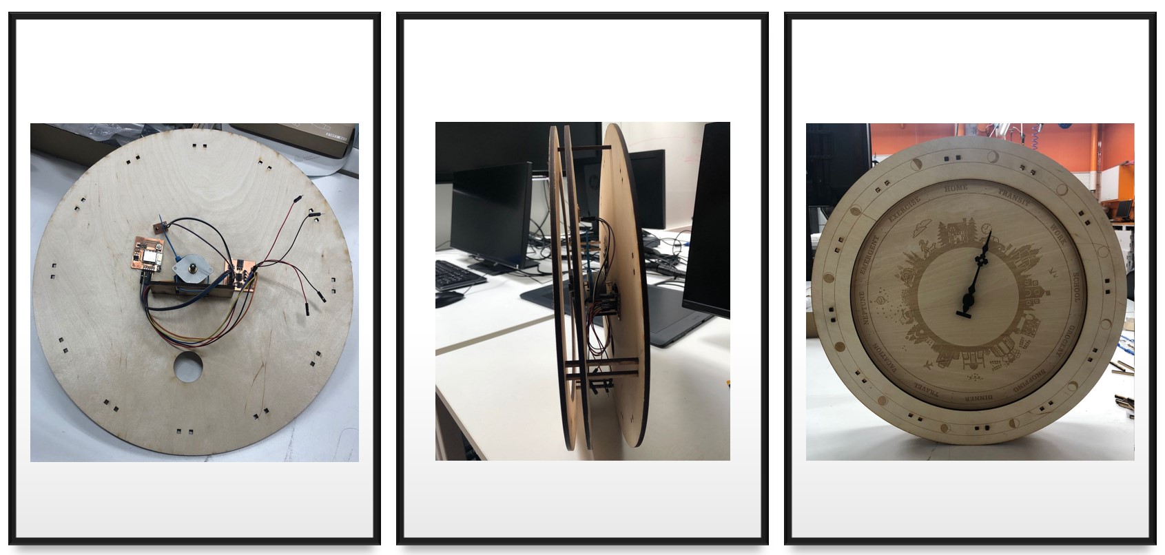
Final Outcome
Files
2D Design
Clock Face Patterns
● CorelDraw File ● PDF File
3D Design
Clock Model
● Clock.f3d ● Axis.stl ● Clockhand.stl
Electronic Design
EAGLE Schematics:
● ESP8266 Schematics ● ATTiny1614 Schematics
EAGLE Boards:
● ESP8266 Board ● ATTiny1614 Board
Arduino Files:
● Stepper Motor Control.ino
● IFTTT_Adafruit IO_ESP8266.ino ● config.h