My major goal of this week has been creating the clock face for my project. I am envisioning to have a clock face with steampunk elements, which will include a collection of gears.Thus, in order to create the gears images, I have tried the following methods:
● Removing background of existing design
● Drawing vectors from skecthes
● Developing 3D models based on vector(svg) files
I have also replicate some interesting designs by reverse engineering.
Raster
GIMP
I have chosen GIMP for raster graphic processing. In many ways, GIMP can serve as a free version of Adobe photoshop. For example, GIMP provides a convenient way of removing the non-transparent background of a picture.
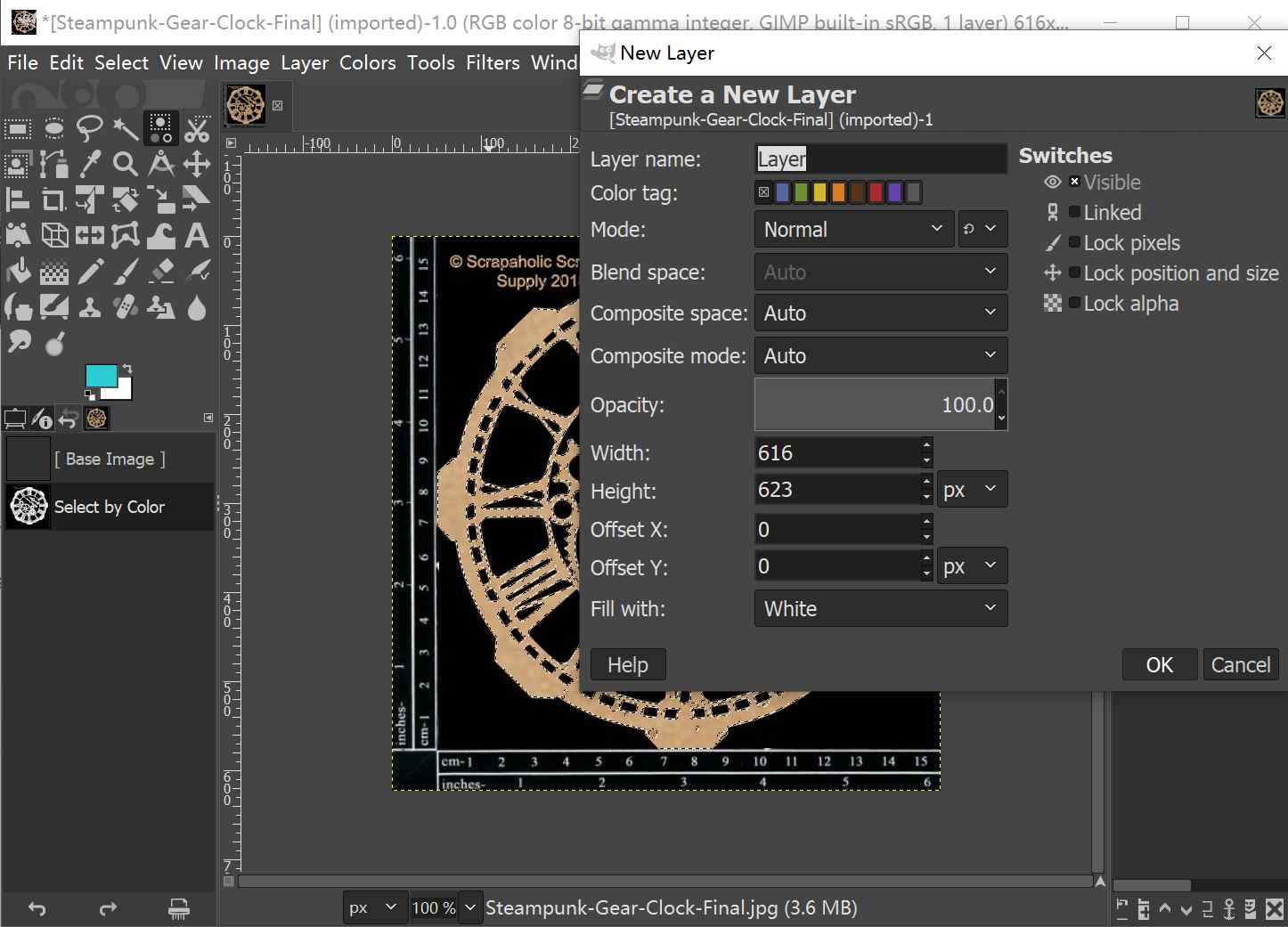
Step 1:
Import the image file and use Color Selection function to select the gear region. Because our goal is to remove the background, an alpha layer, which is transparent, should be created.
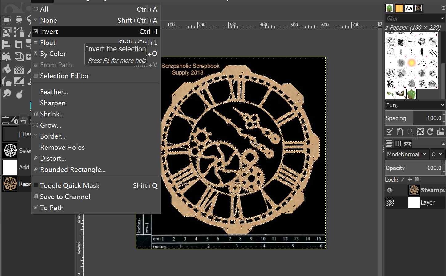
Step 2:
Use the Reverse Selection function to select the background and to retain the image itself.
Step 3:
Use the Edit Tab >> Clear function.
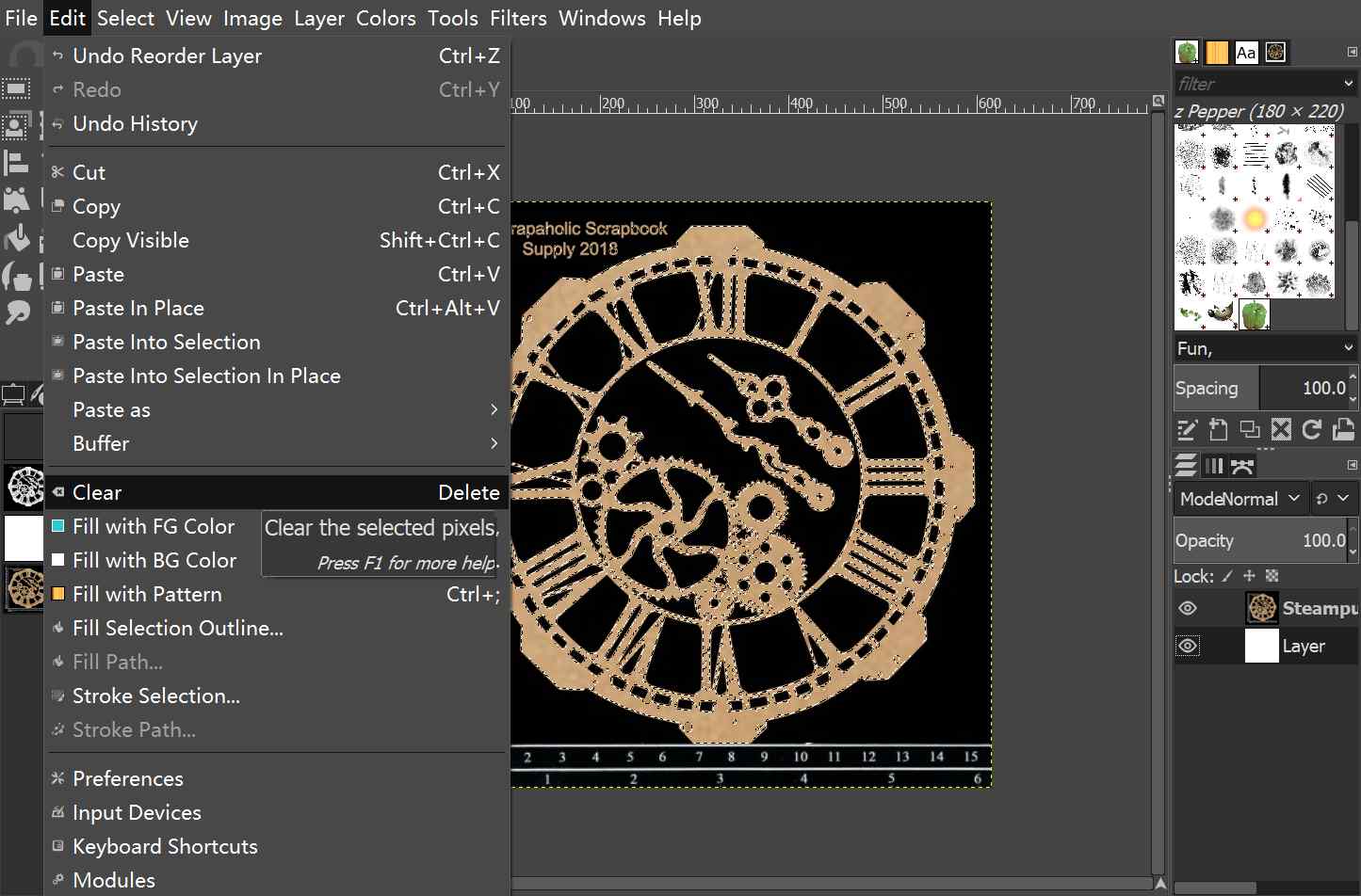
Then the background will be successfully removed.
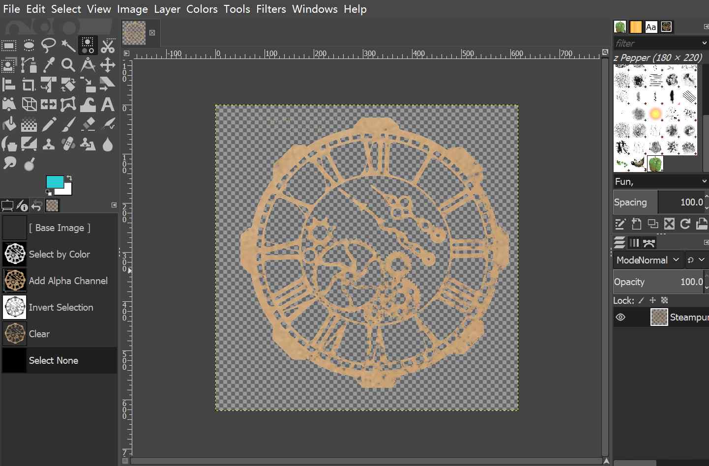
In general, GIMP is very easy to use and have many convenient functions. However, maybe it is due to my novice in using this software, the quality of the processed image is not ideal. Moreover, because the raster format pictures provide very limited support to the following modeling process, I spent the majority time in exploring vector design tools.
Vector
I have tried both Inkscape and CorelDRAW for vector graphic processing. Inkscape is a very powerful open-sourced tool with simple User interface, while CorelDRAW is a design tool with excellent User interface but provides only 16 days of trials. I prefer to use CorelDRAW because of its wonderful UI design.
Inkscape
Inkscape can provide many useful functions, as shown in the screenshot. Users can easily create common shapes and objects. However, to me, the User Interface is not in its best version. The menu items buttons are tiny (which may be due to my computer configuration) and that will slow down the users' operation according to Fitts's law.
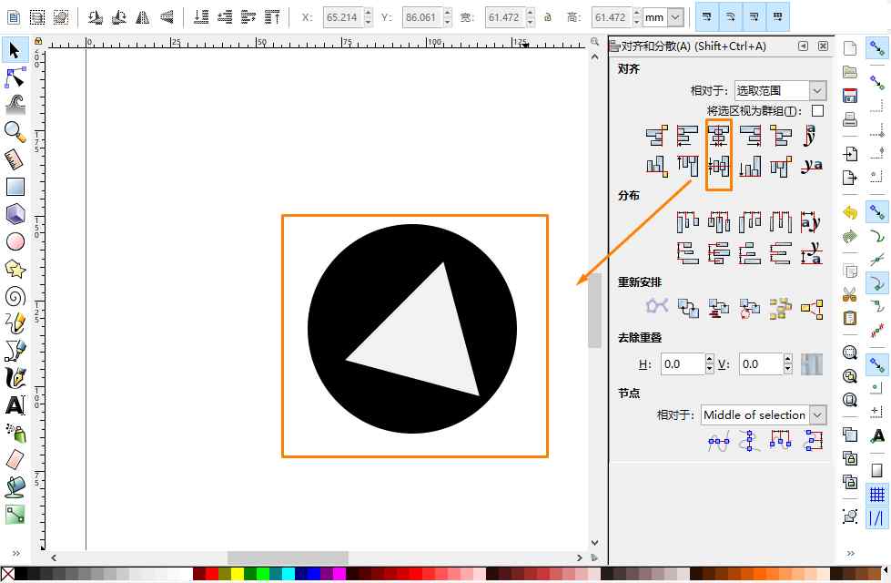
Also, there are tiny issues that do not fit well with my habits. For example, as shown in the screenshot, I have aligned the blue circle and the triangle by centering them on both the vertical axis and horizontal axis. But apparently, the two shapes are not concentric as expectednot concentric as expected. Hence, I switched to other software.
CorelDRAW
From my point of view, CorelDRAW has similar settings to Inkscape but with a better user interface design and more convenient shortcuts. CorelDRAW is not open-sourced, but it provides a 16-day trial. Thus, it may be a good idea to finish all the vector designs within 2 weeks before the temporary license expires.
CorelDRAW provides great support in creating the 2D design of gears. By rotating and integrating the common shapes, such as circles, triangles, and trapezoid, I was able to create gears with very simple procedures.

Creating a gear in CorelDRAW
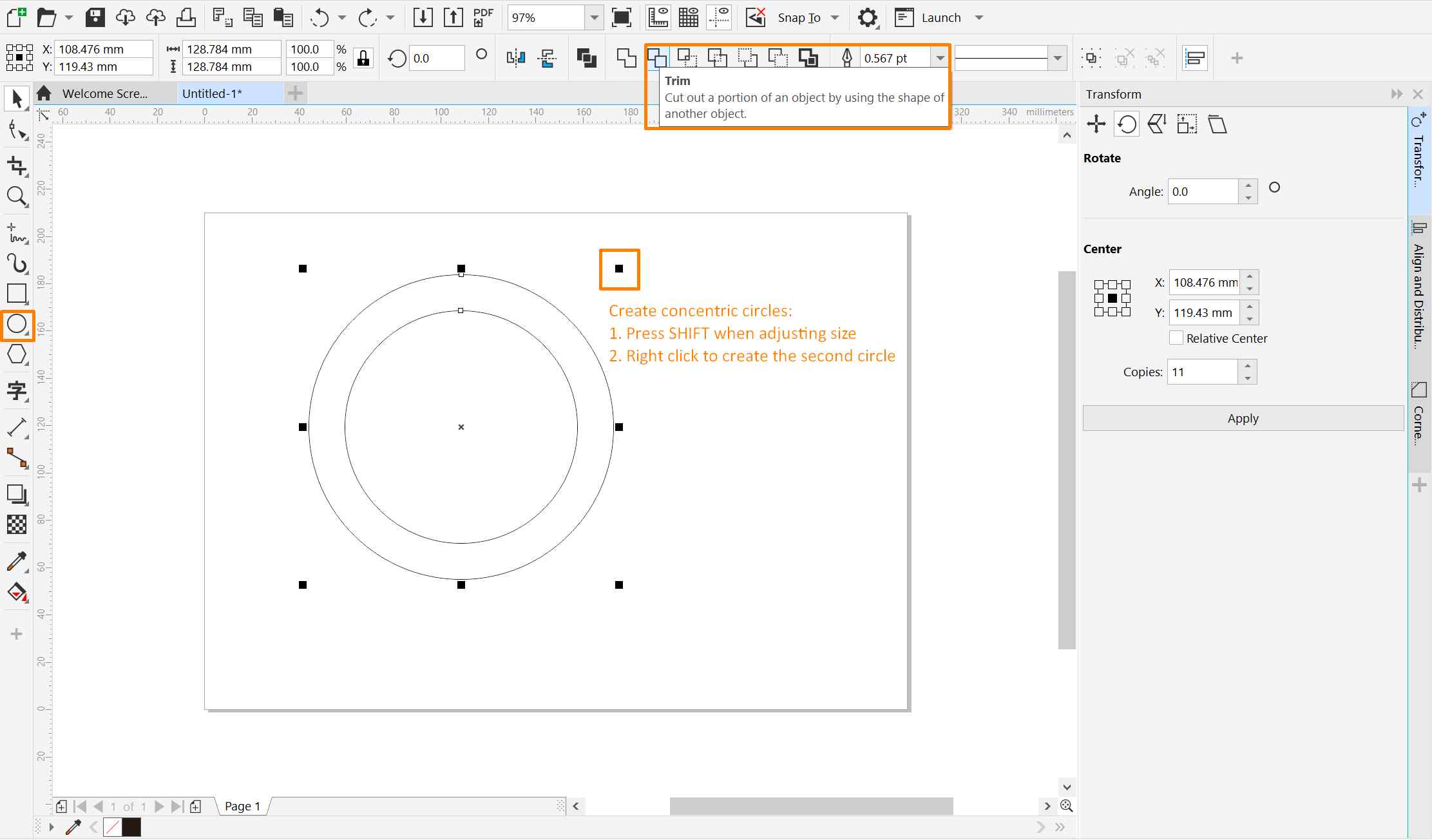
Step 1: create two concentric circles following these procedures:
1.Using the Elipse button on the left menu bar while pressing Ctrl button on the keyboard to create a circle
2.Pressing Shift on the Keyboard and adjusting the size of the circle
3.When the second circle reaches the ideal size, right-click the mouse and the second circle will be created.
4.Use the Boolean function to make a ring shape for the gear:
Select the two concentric circles. Select the Trim tab on the top toolbar to remove the overlapping circle and retain the ring shape.
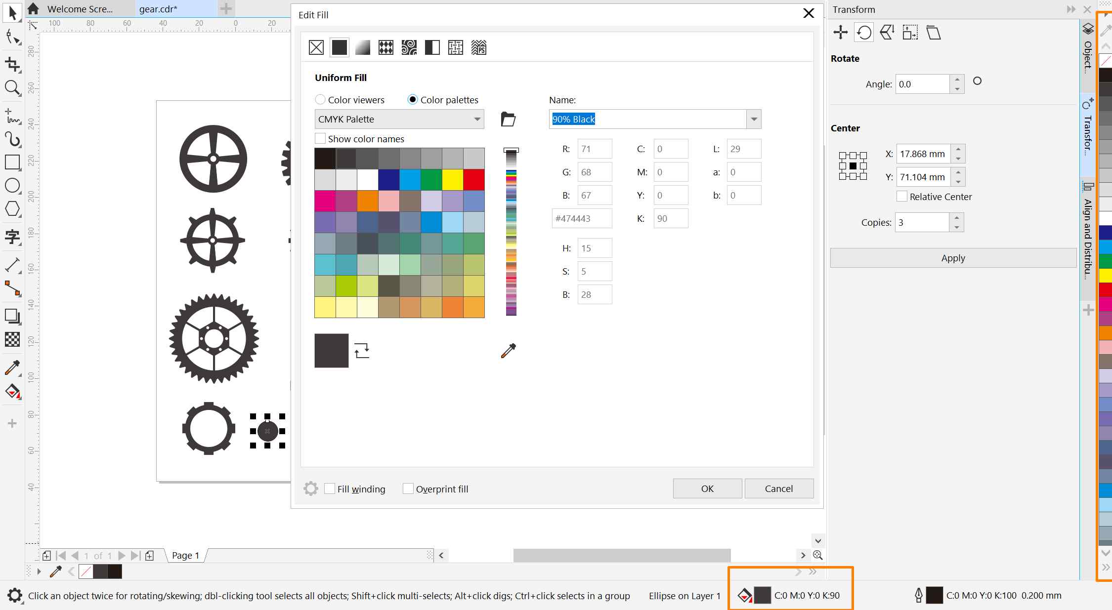
If this is for 2D design, colors can be added at this point. Users can either use the color panel on the right bottom corner of the interface or directly drag the color from the right toolbar to the selected object. Dragging to change color can apply to both the fill and edge colors.
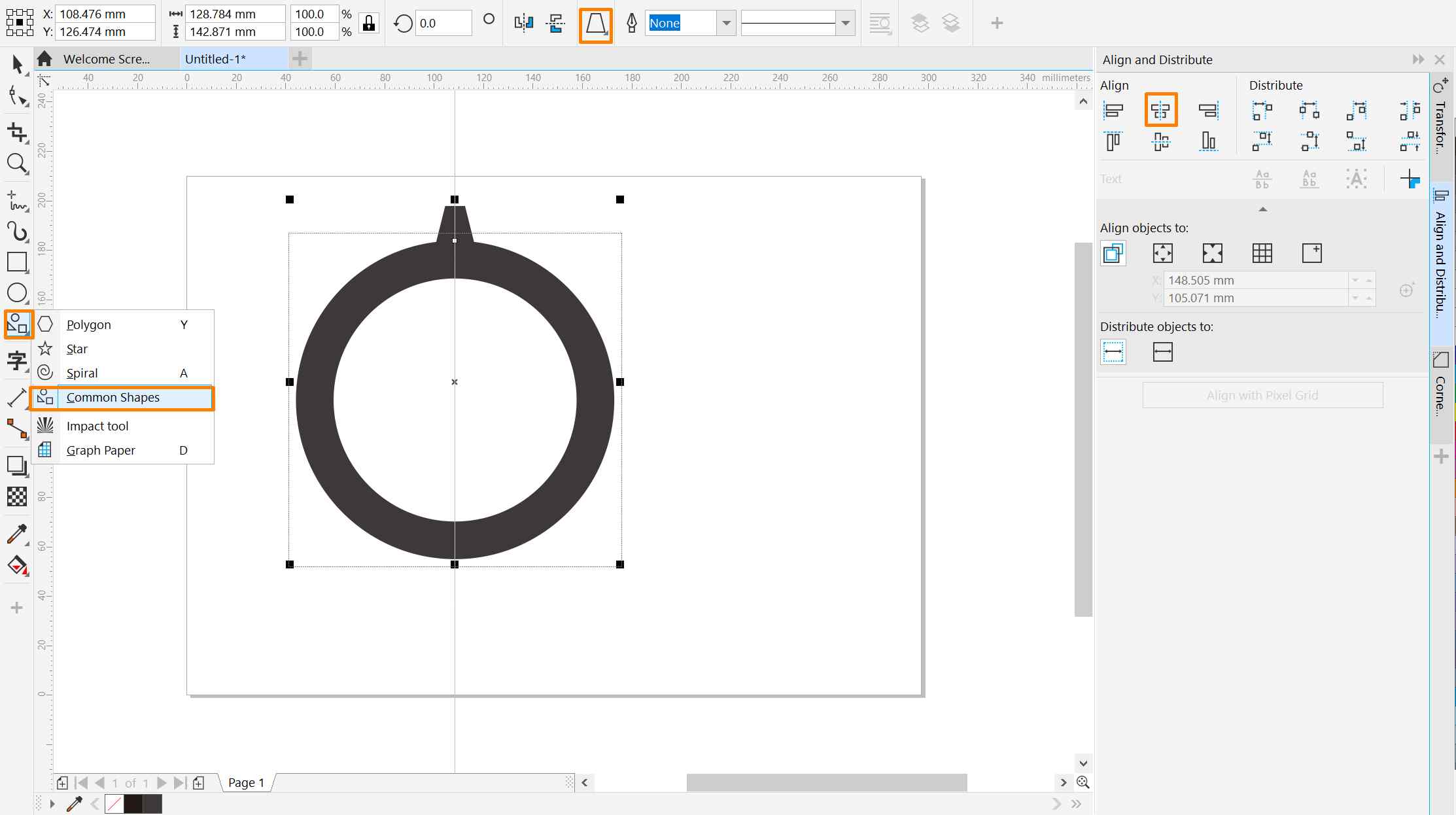
Step 2: create the gear tooth:
1. Click on the Common Shapes on the left toolbar
2. Select the trapezoid shape on the top toolbar
3. Create a trapezoid and align it to the ring shape by centering them vertically
Step 3: create more gear teeth:
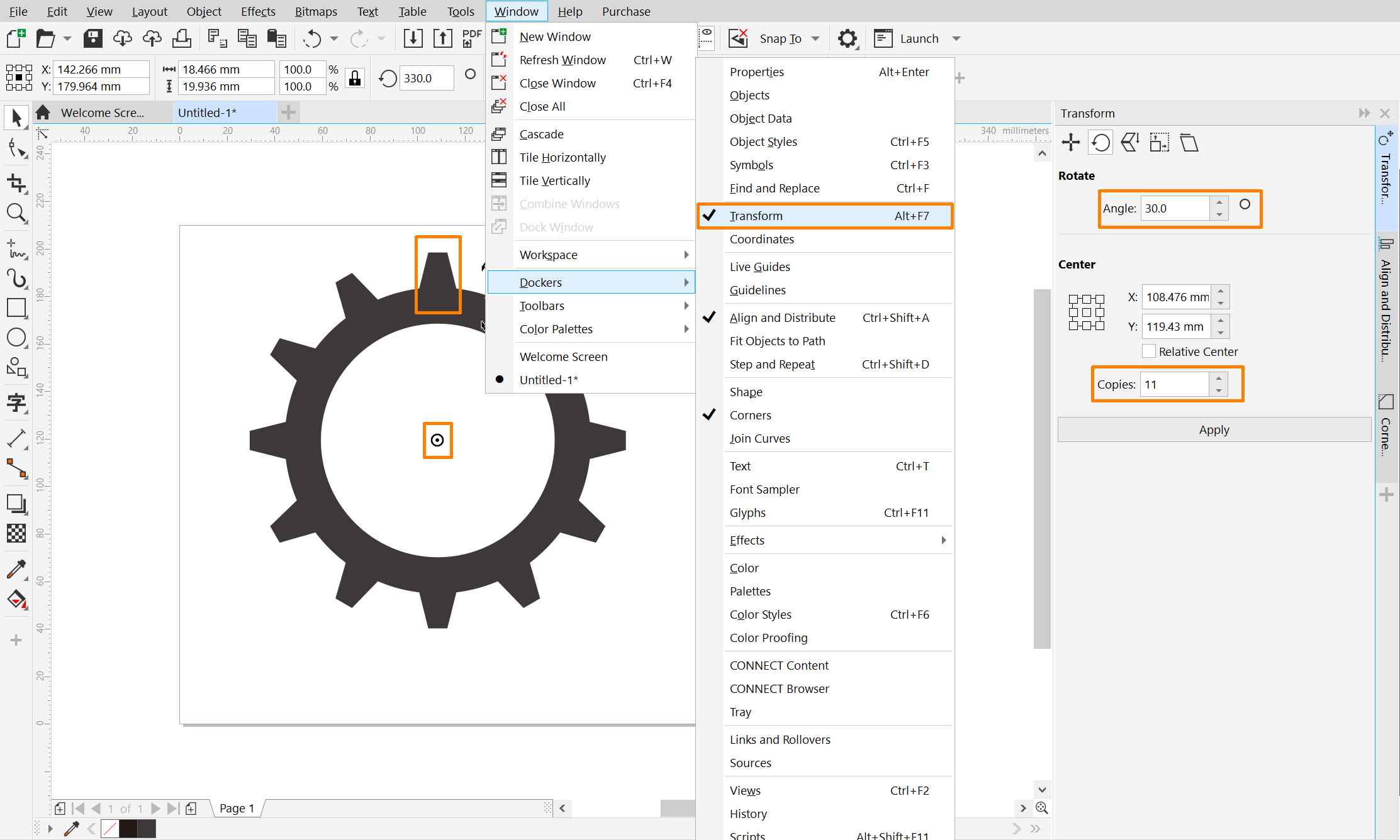
1. Access the Transform function: Window >> Dockers >> Transform
2. Change the rotation center: click on the trapezoid to evoke the rotate mode and drag the rotate center to the center of the ring
3. Input the ideal rotate angle and number of copies in the transform docker
After clicking "Apply" button, the gear teeth are created.
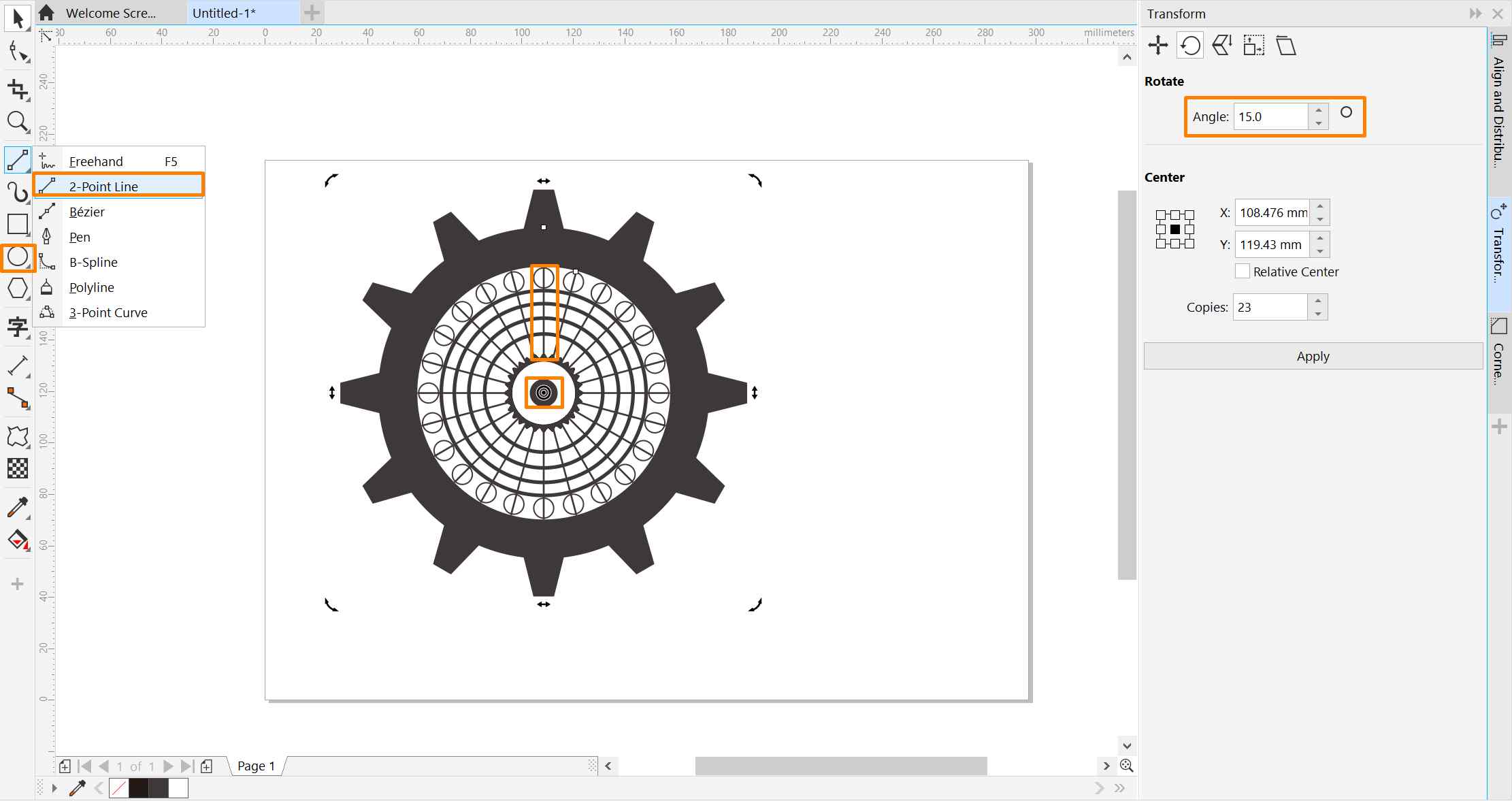
By adding more elements and shapes on the basic gears and well utilizing the transform function, it is not hard to generate aesthetically pleasing gear designs.
Tips for Novice Like Me
● Group elements before alignment can avoid unexpected aligning errors.
● Do not forget to change the rotation center otherwise it will spin around its default center.
● Creating Concentric shapes: Press SHIFT when adjusting an element and then right click.
● When elements overlap together and become hard to select, use the Object Docker
Creating gear SVG files for 3D modeling
It is possible to export the gear design as SVG files that can be directly used by 3D modeling software like Fusion 360. However, in this case, it is crucial to ensure the shape has a closed contour, otherwise, the 3D design software will not well recognize the different sections of the gear. Due to my novice in graphic design, my way of creating the closed contour is based on Boolean calcultion, which may be a less optimal choice. I will update this section, if I found a better method of closing the contour. By far, I have been creating a gear vector for 3D modeling purely based on Boolean function and hence follow a different set of procedures.
Step 1: Similar to the previous design:
Create circles>> Trim the Boolean overlap >>Create trapezoid >>Center by vertical
1. Create concentric circles and trim them
2. Create a rectangle and rotate by 90° and make 1 copy
3. Create a trapezoid and rotate by 30° and make 11 copies
4. Select all components and used the Boolean Weld function located on the top toolbar
5. Export SVG files: File tab >> Export >> Choose SVG format
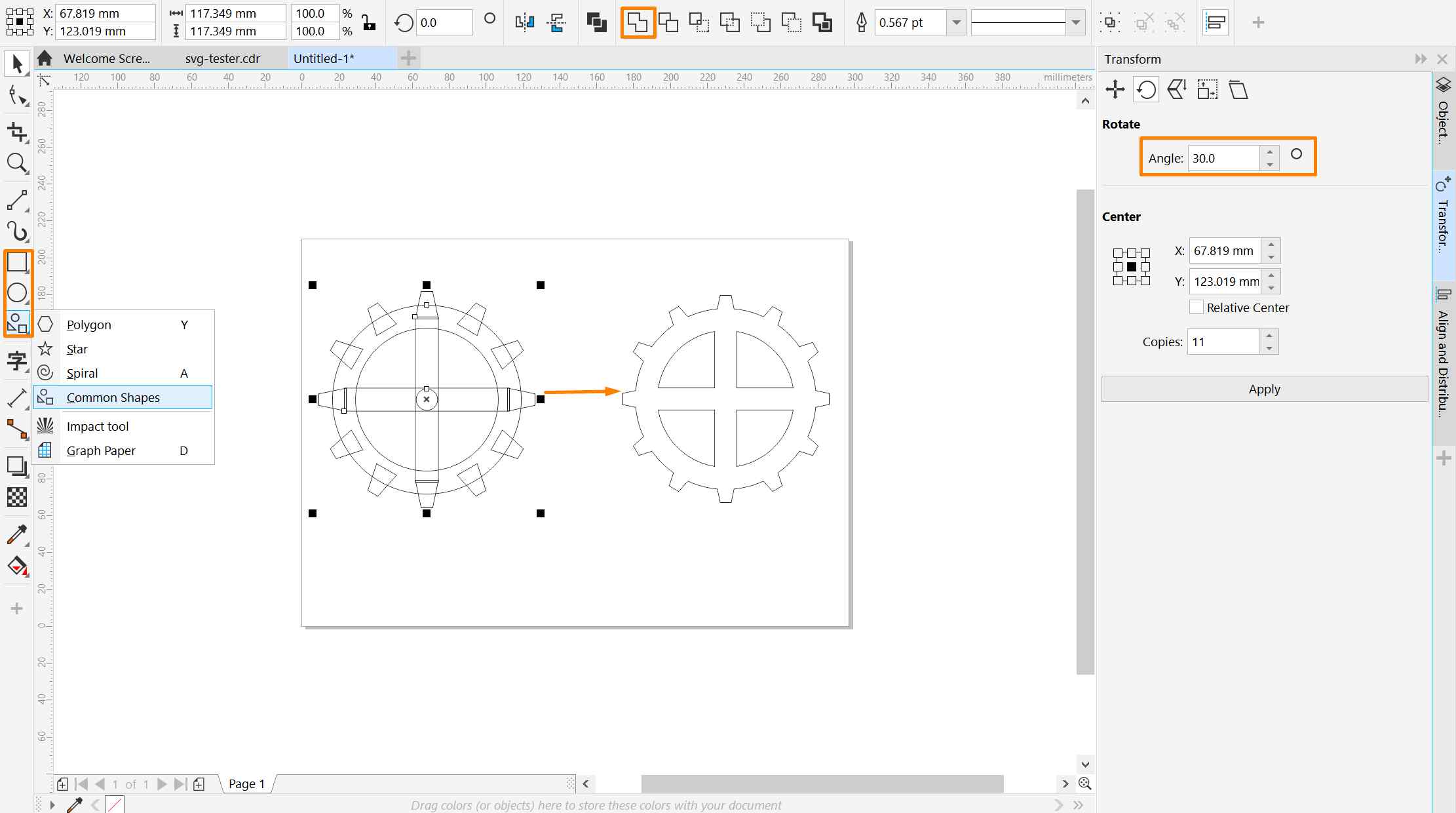
It is important to ensure the contour of the combined shape is closed, otherwise the lines will not be accurately recognized by 3D design modeling tools.
3D Design
Fusion 360
I used Fusion 360 for 3D design. Fusion 360 software is a 3D CAD, CAM, and CAE tool from Autodesk, which provides free education licenses to students with University email addresses. It provides strong support to 3D design modeling, rendering, simulation, and digital fabrication.
Instead of sketching in Fusion 360, I choose to import SVG files that I created using CorelDRAW. The SVG file can be placed either on a surface on an object or on the platform. The most important issue in this process is to ensure the contour of shapes are closed and accurately recognized. Adjustment can be made with Fusion 360 if the pattern recognition is not perfect.
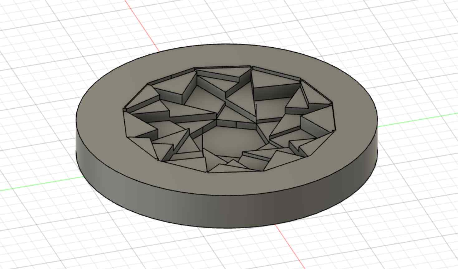
Curve the pattern on a surface
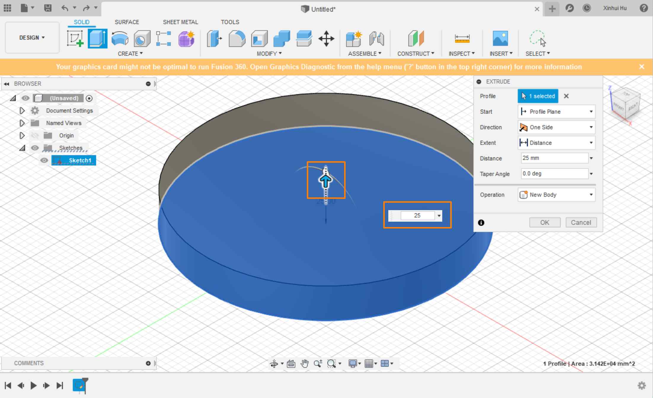
Step 1: Select Platform and create a circle
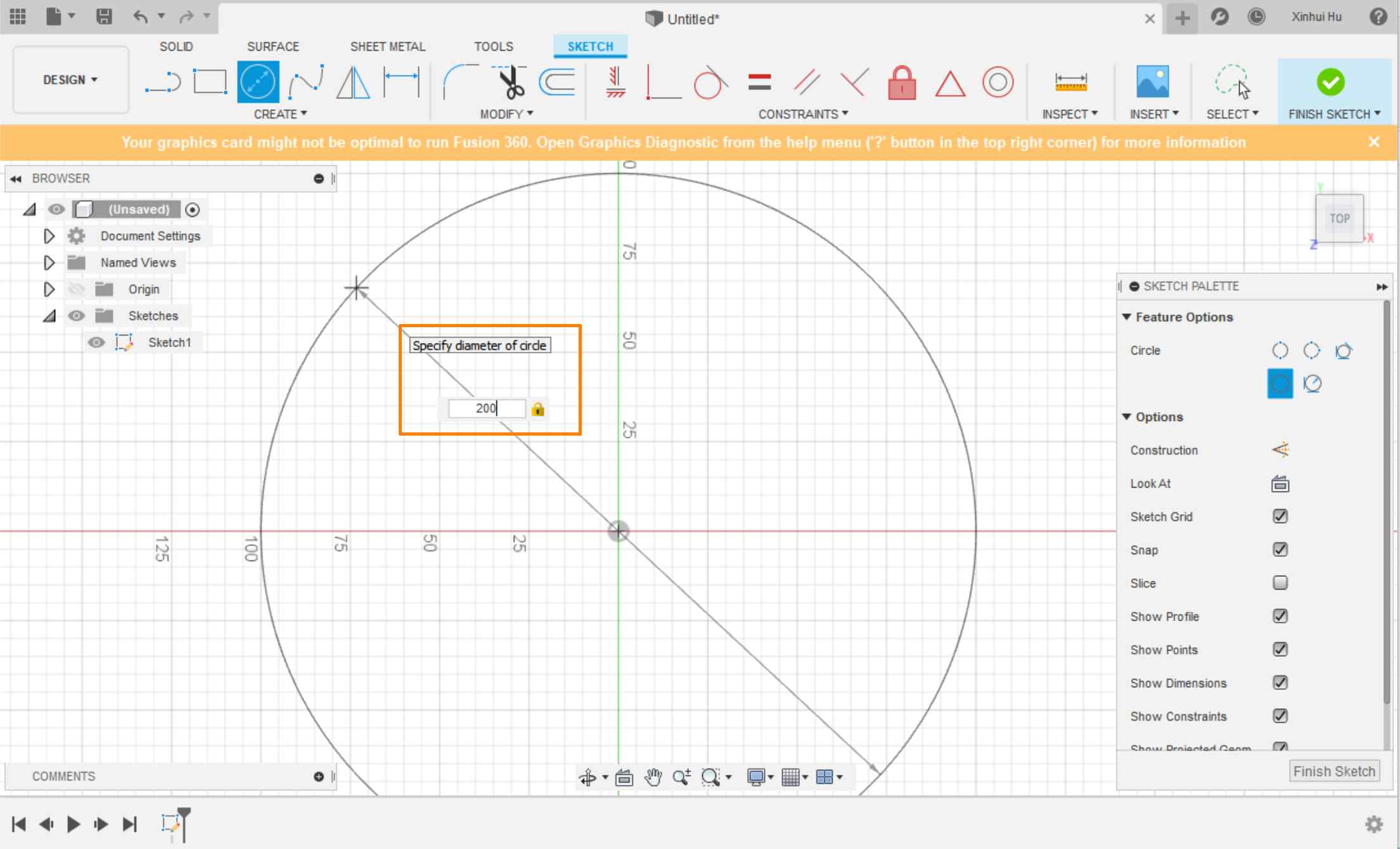
Step 2: Add the thickness
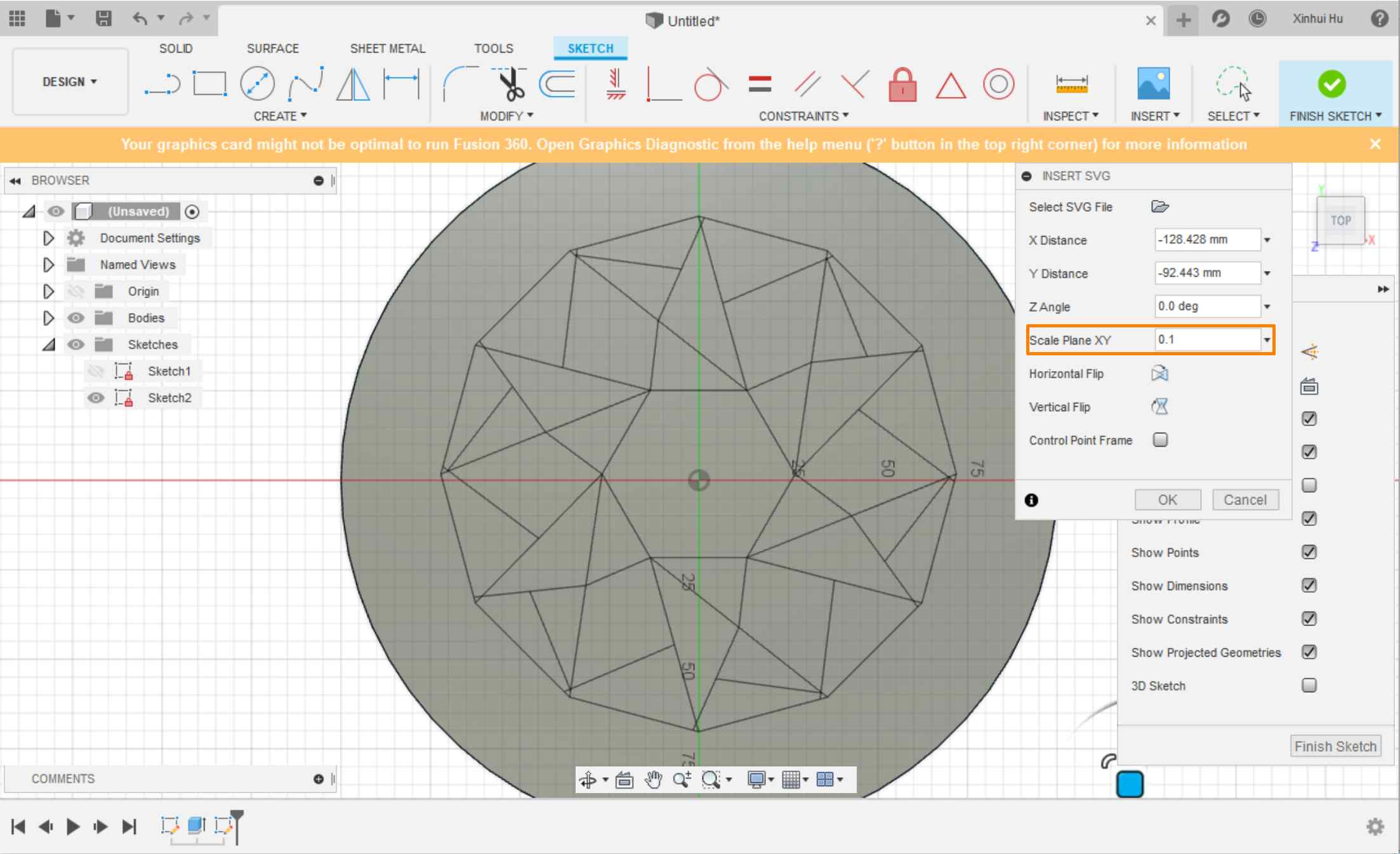
Step 3:Select a surface and insert SVG file and insert SVG.
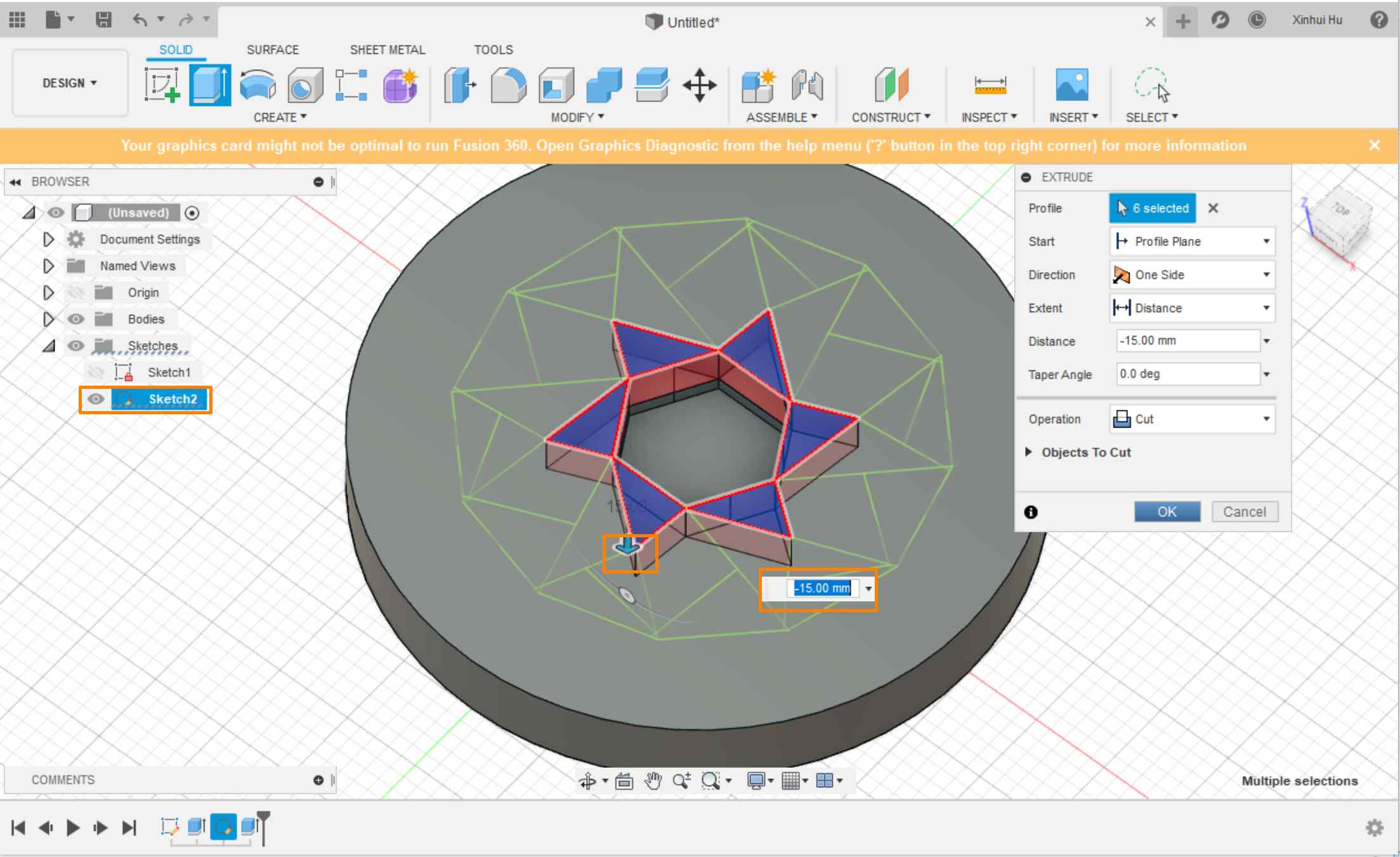
Step 4: Select the facets and change the thickness to make the curve effect
If the contour is not accurately recognized, the details can be adjusted.
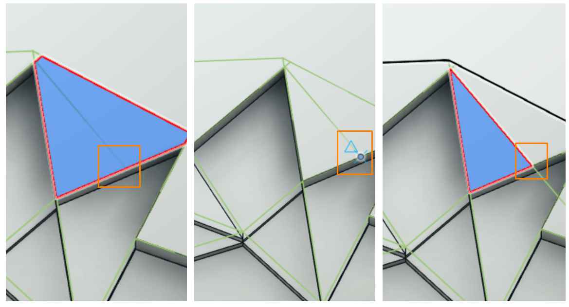
Each facet can be individually modified
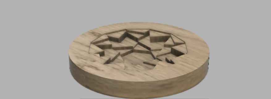
Fusion 360 also support rendering the simulation and materials
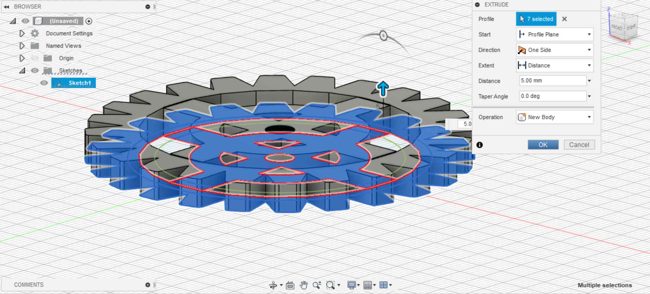
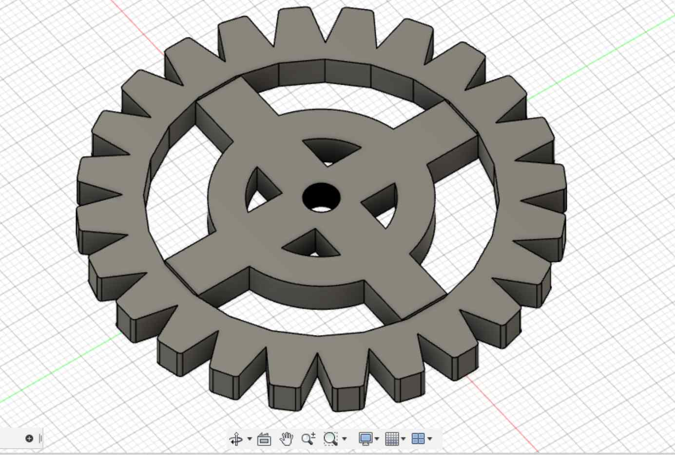
Pull the parts from sketch
It is also convenient to direct use the pull function
Files
The files can be downloaded here
- Gear Design Files
- cdr files (For CorelDraw)
- svg files
- f3d files
- stl files
- Extra Fun: Fnacy Gears and Magic Circle
