Individual Assignment
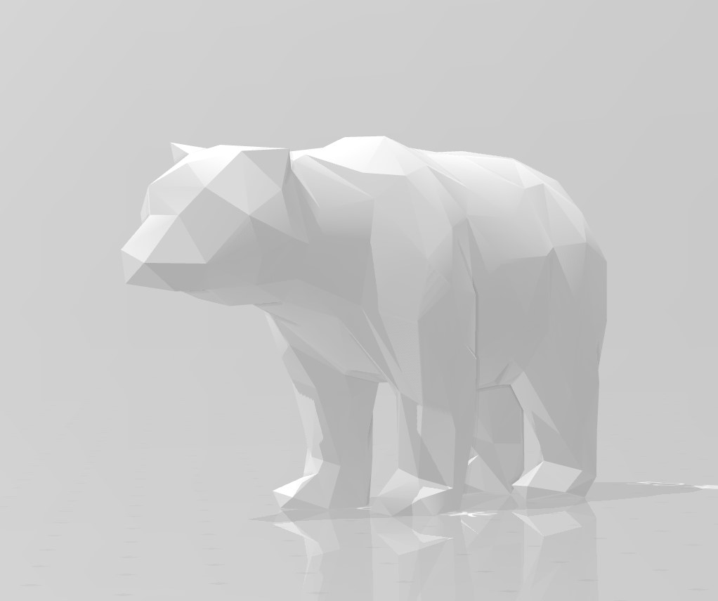
In this week, I would like to create a grid shelf that has an animal appearance, similar to the product shown below.

Inspried by Yuichi TAMIYA, I found that Slicer for Fusion 360 is a great tool to achieve this goal. However, in my case, the exported plan from the slicer 360 cannot be directly used for the CNC machine in our lab. Thus, after slicing the model, the plan need to be further processed in Fusion 360 for cutting.
Model Slicing
1. Find 3D model
The first step is to find an appropriate 3D model for slicing. I have found several polar bear model from Thingiverse. After trying to import these models into Slicer for Fusion 360, I found that the ideal model for this purpose should have minimal details, like furs and paws. Thus, I have chosen a low-poly bear model.
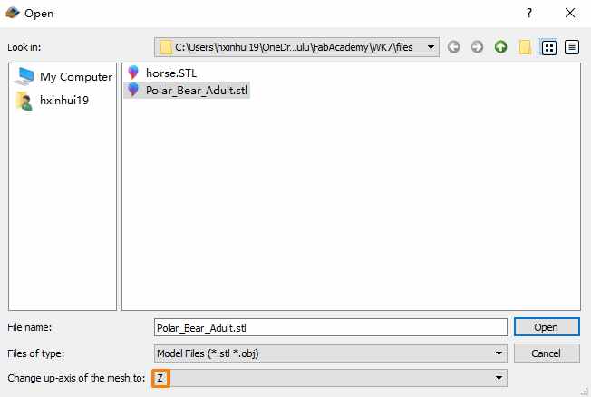
2. Import Model
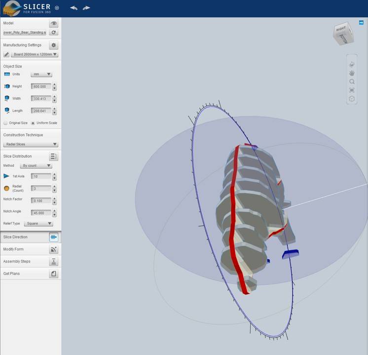
The direction of the Slice depends on the up-axis of the model. While it can be changed in the later part, having the model imported in an convenient angle for manipulation will be highly recommended.
3. Customize the Settings
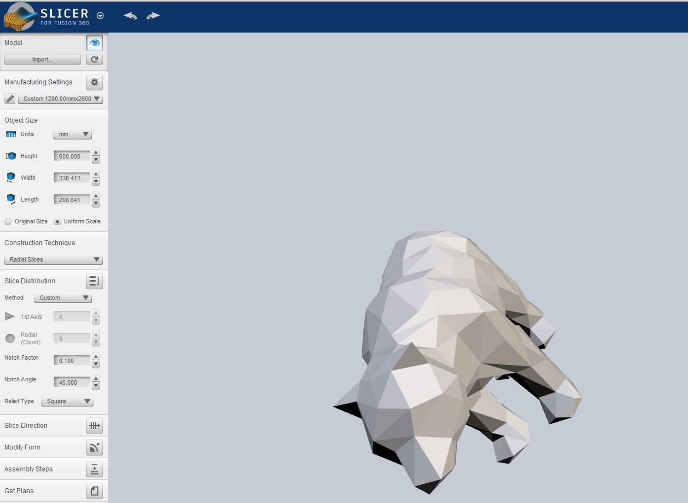
The operation of slicer for Fusion 360 has been quite simple and straightforward.By going through these functions will allow the users to get the 2D plan of the sliced model.
Step 1: Manufacturing settings
This is the section where the users can set the parameters of the board that will be cut. For example, in my case, I set the parameters as:
● Length: 2600 mm
● Width: 1200 mm
● Thickness: 11 mm
● Tool Diameter: 8 mm
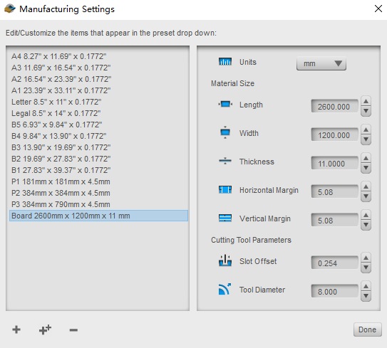
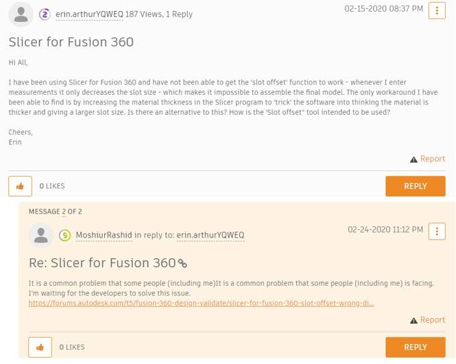
*There is a bug in manufacturing setting. While users can set the slot offset and thickness, the changes will be reflected in the outcome if the model is sliced radically. Thus, if the model will be sliced in the radical way, the slot width issue need to be taken care of.
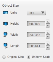
Step 2: Object Size
This function allows the user to adjust the dimensions of the assembled outcome. In my case, I am expecting to use half of the board, so I set the height to 600 mm. The other dimensions will automatically change to match the same ratio.
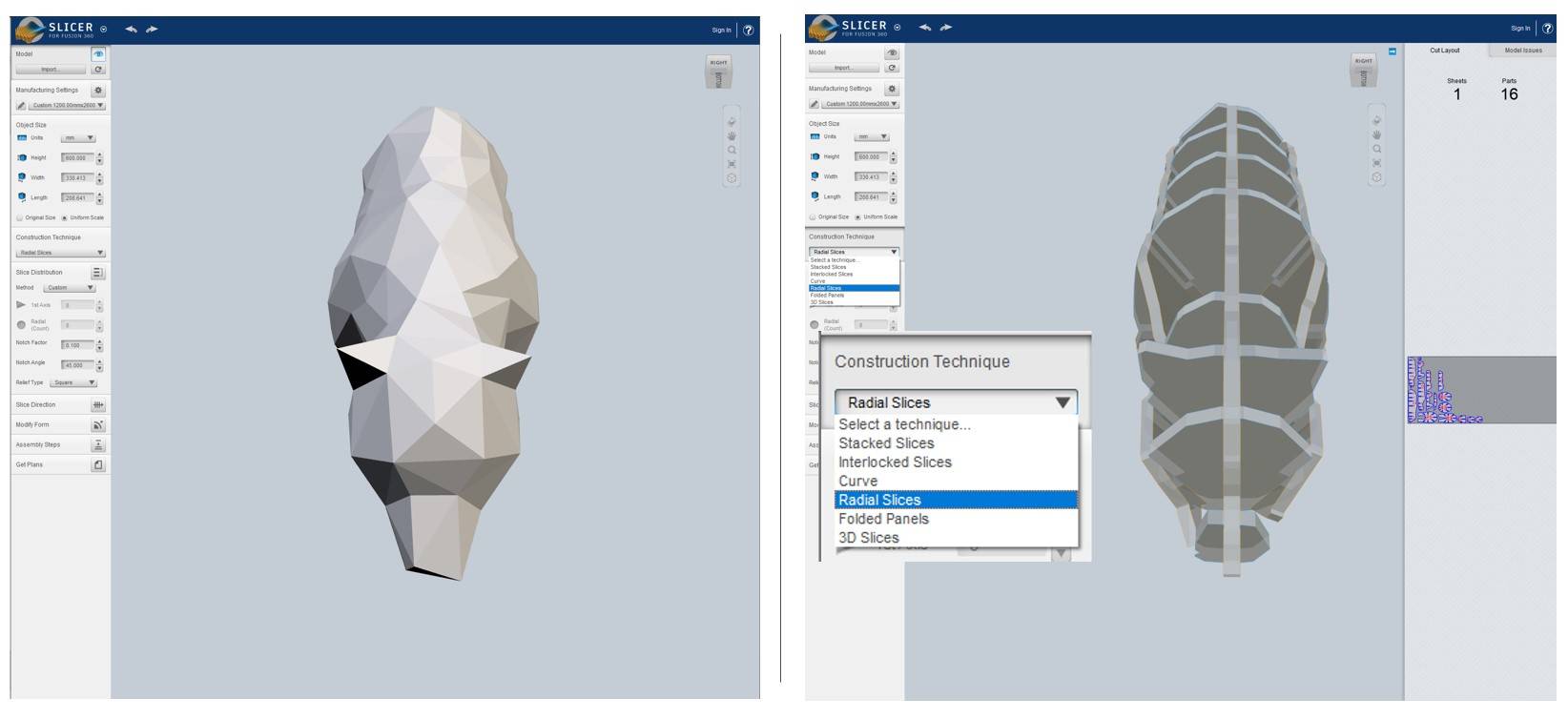
Step 3: Construction Technique
This is the section where the user select the style of slicing
In my case, Radial Slices may be the best choice, because it well retains the shape of the bear while providing adequate space as a shelf.
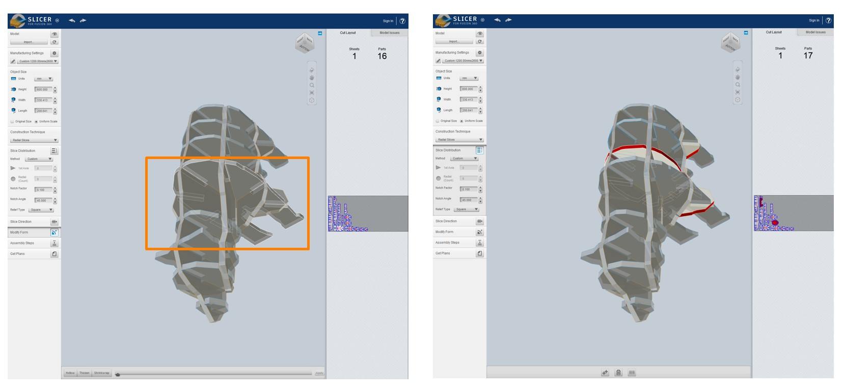
If the software recognizes the pieces to be problematic, it will show the error pieces in the red color. But this is not always reliable, so the users need to make their own decision and adjustment.
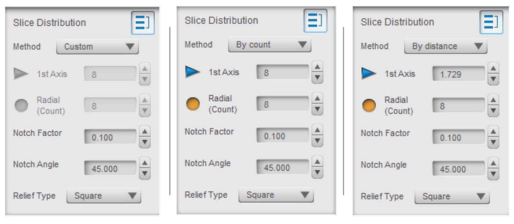
Step 4: Slicing Distribution
This function allows user to adjust the distribution of the slices by the following methods:
● Custom
● Count
● Distance
The Relief Type can also be adjusted in this section. Many users would choose the dog bone type for cutting accuracy and assembly convenience. However, because I will need to deal with the slot offset bug in later step, I chose to use sqaure relief.
The Slicing Direction function allows user to change the slicing axis of the model. Because I am pretty happy with the current slicing axis, I skip this function.
Step 5: Modify Form
This function allows the user to adjust the location of each slice. The selected piece will be shown with a white outline. While users can delete pieces in this step, adding additional piece can only been done in the Slice Distribution section by adjusting the count.
The Assembly Steps function can show the users how the outcome would look like with a cardboard model.
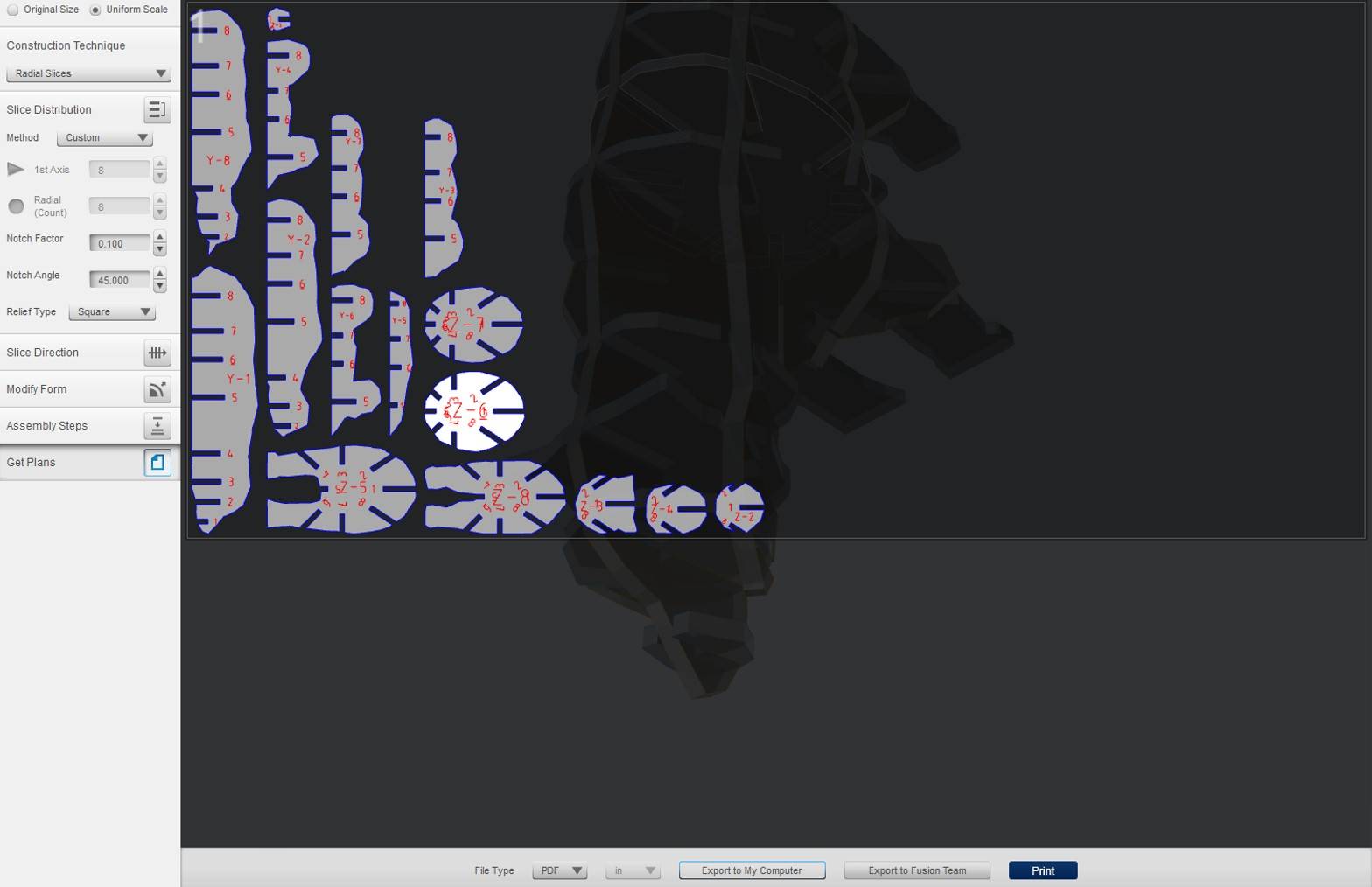
Get Plans
This function allows the user to export the 2D plan to the computer. I chose to export the PDF version, which can be conveniently convert into SVG file, as I will need to import the contours in Fusion 360 for further edition.
Tool Path Generation
Each type of CNC machine has its own requirement on the tool path file. In Fab Lab Oulu, the tool path file is best generated with Fusion 360.
Step 0: Install Necessary Setting files
I have downloaded these files and put them in the same folder that I will save the tool path file.
CPS File:FabLabCNC.cps
Tool Library:FabLab Routeri Tool.hsmlib
These file will set the parameters for the CNC machine when exporting the tool path file.
Step 0.5: Dealing with the slot width bug
The PDF file of the cutting plan exported from Slicer for Fusion 360 can be converted into SVG file with CorelDraw and Inkscape.
I personally prefer Inkscape in this case, because CorelDraw may automatically change the scale in some cases.
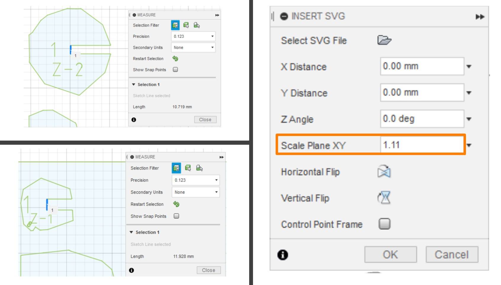
Then, the SVG file can be imported into Fusion 360. As mentioned above, there is a bug in the software when choosing radial slice, which will make the slot width 10.719 mm regardless of the slot offset and material thickness settings. This issue can be solved at this step.
When importing the SVG file, adjust Scale Plane XY to 1.11. In this way, the slot width can be set to about 12 mm.
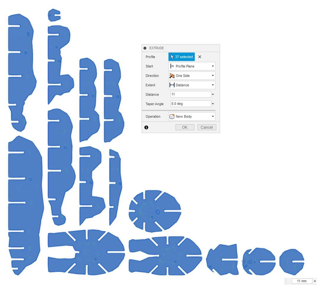
Step 1: Extrusion
Select all contours and extrude by 11 mm, which is the thickness of the material.
In this step, the arrangement of the pieces can be adjusted to better utlize the board.
Step 2: Manufacturing Set up
- Switch from the Design Interface to the Manufacturing Interface via the Button on Upper Left corner.
- Top Menu Bar >>Milling >> SETUP >> New Setup
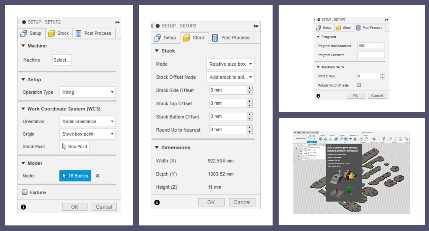
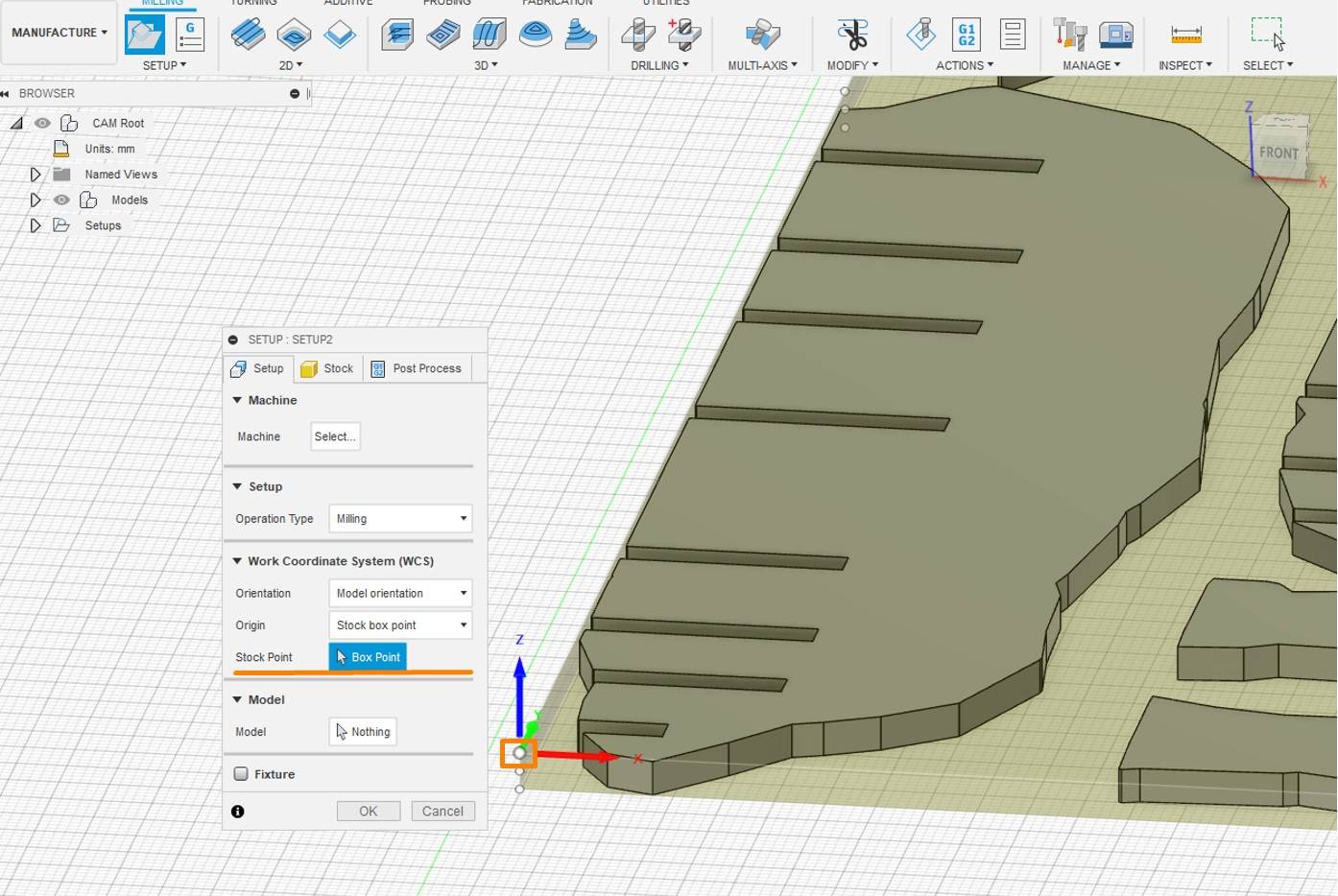
-Setup:
Operation Type: Milling
Stock Point: Box Point
-Stock: Set all offset values to 0 mm
Step 3: 2D Contour Settings
This is the step where the milling parameters are determined.
-Evoke the setting tabs via Top Menu >> 2D >> 2D Contour
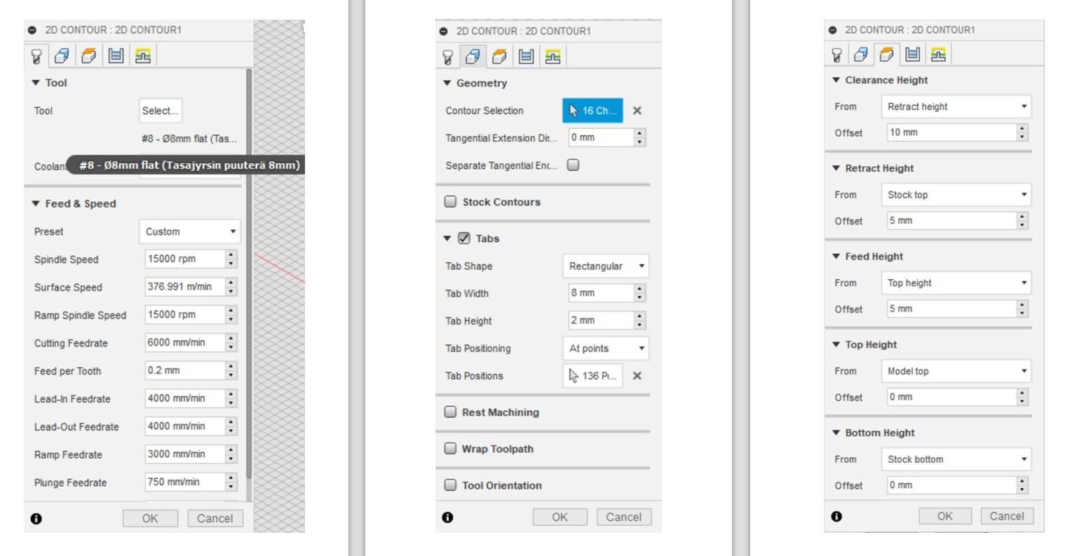
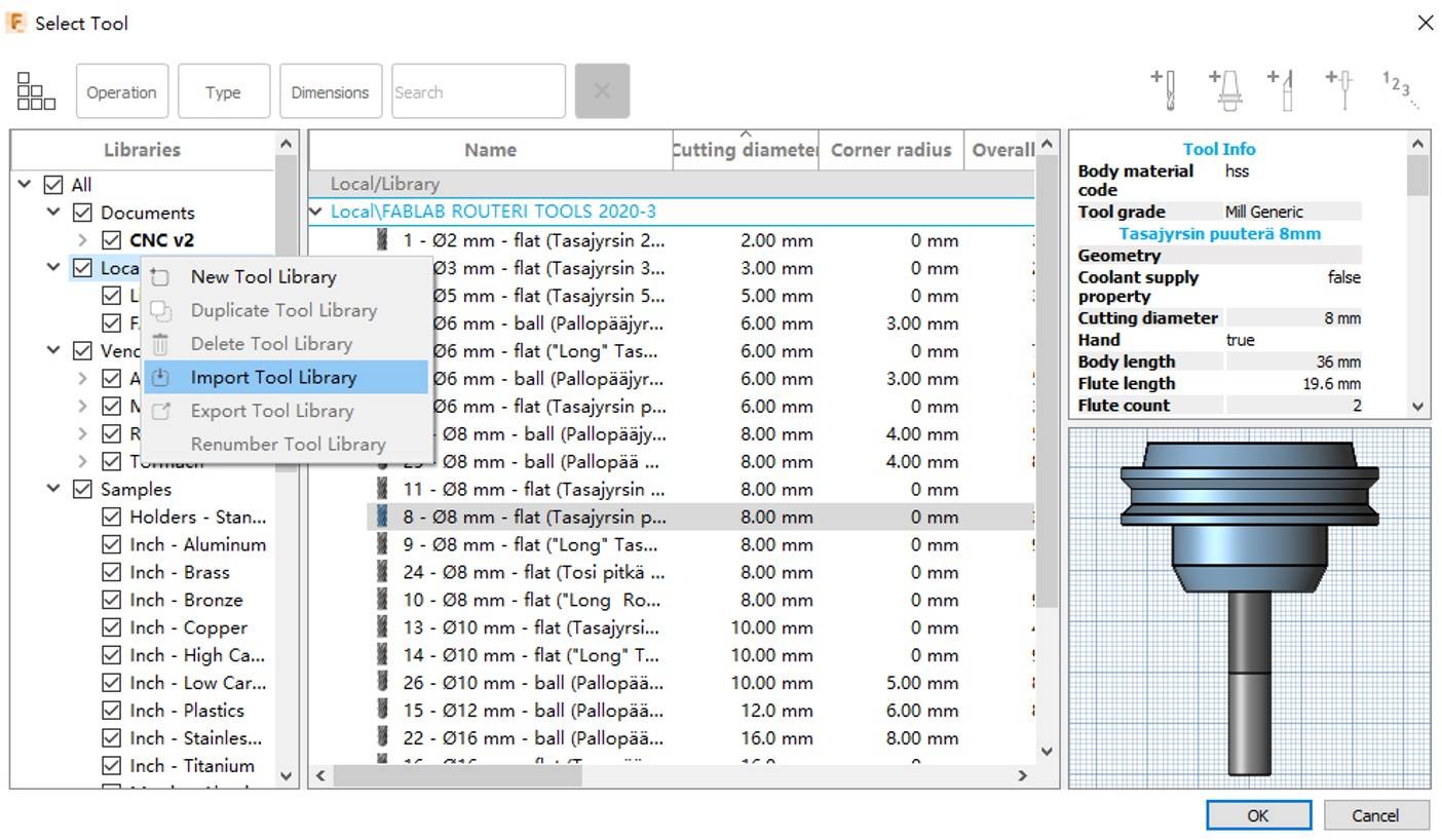
-Tool Section
Tool:Tool>>Import Tool Library >> Local >>FabLab Routeri Tool>> 8 mm flat Tasajysin puutera 8mm
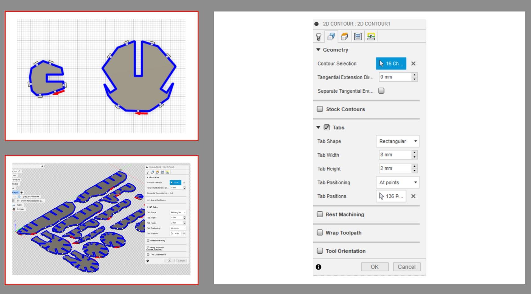
- Geometry Section:
This step allows user to add tabs to the pieces. It will be very dangerous if the milled parts directly detached from the board as the milling bit moves. So adding tabs will allow the pieces to stay connected with the board, while the tabs can be manually removed afterwords.
In my case, I have set the tabs width: 8mm height:2mm. My contours have many curves, so I added the tabs manually, as the auto-generated tabs are not always at the reasonable position.
Tips:
- Do not put tabs in the slot
- Do not make the tab too thick if you only have a hand saw. It takes huge effort.
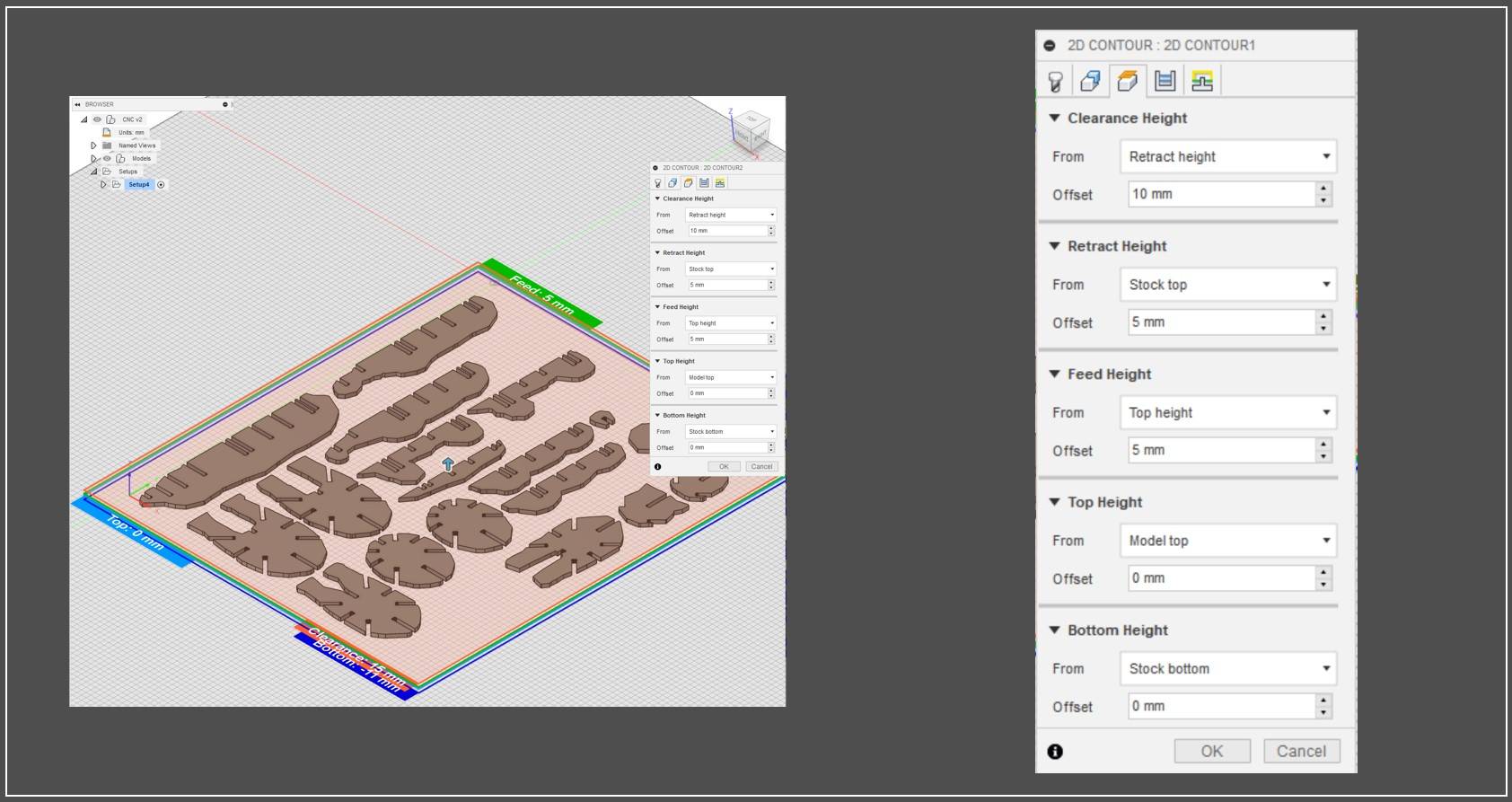
-Height Section:
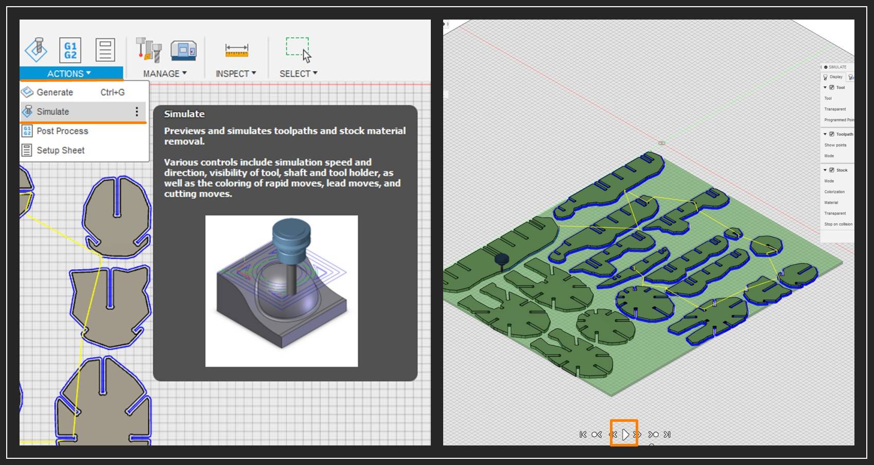
Step 4: Simulation
Initiate the simultion panel via Action >> Simulate
-selecting stock will demonstrate the board
Clicking the PLAY button at the bottom of the page will start the animation of the tool moving path.
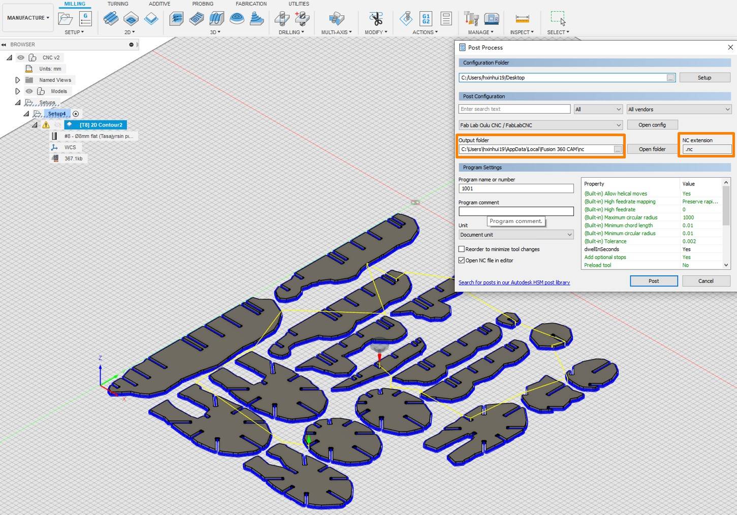
Step 5: Generating Path file
Action >> Post Process
Post Configuration >> FabLab CNC >> Output folder: [The folder where the cps. file locates]
Then the nc file can be exported to the folder path.
Board Cutting
CNC machine calibration
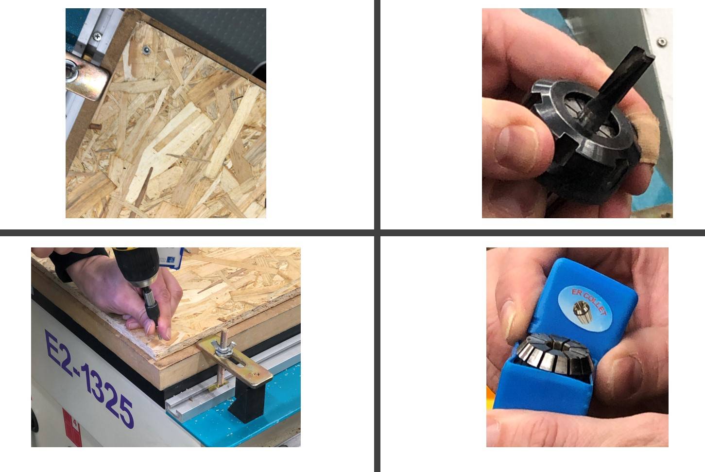
1. Install milling bit and board
Theoretically, the first step should include turning on the machine, changing the milling bit, and screwing the board. But the machine was already on and the 8mm flat milling bit was already installed, so I skipped these procedures.
The board is screwed onto the working platform for safty concerns.
2. Set Origin
Back to Machanical Origin >> All Axes
-This command set the starting point to zero.
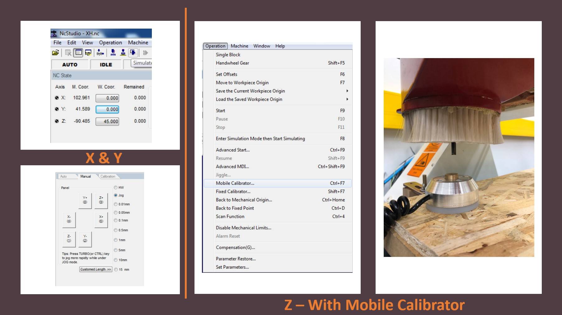
3. Calibrate X,Y,Z
- X and Y are set to 0 with the position panel.
- Z is set with mobile calibrator
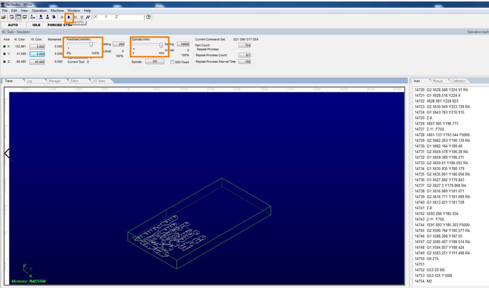
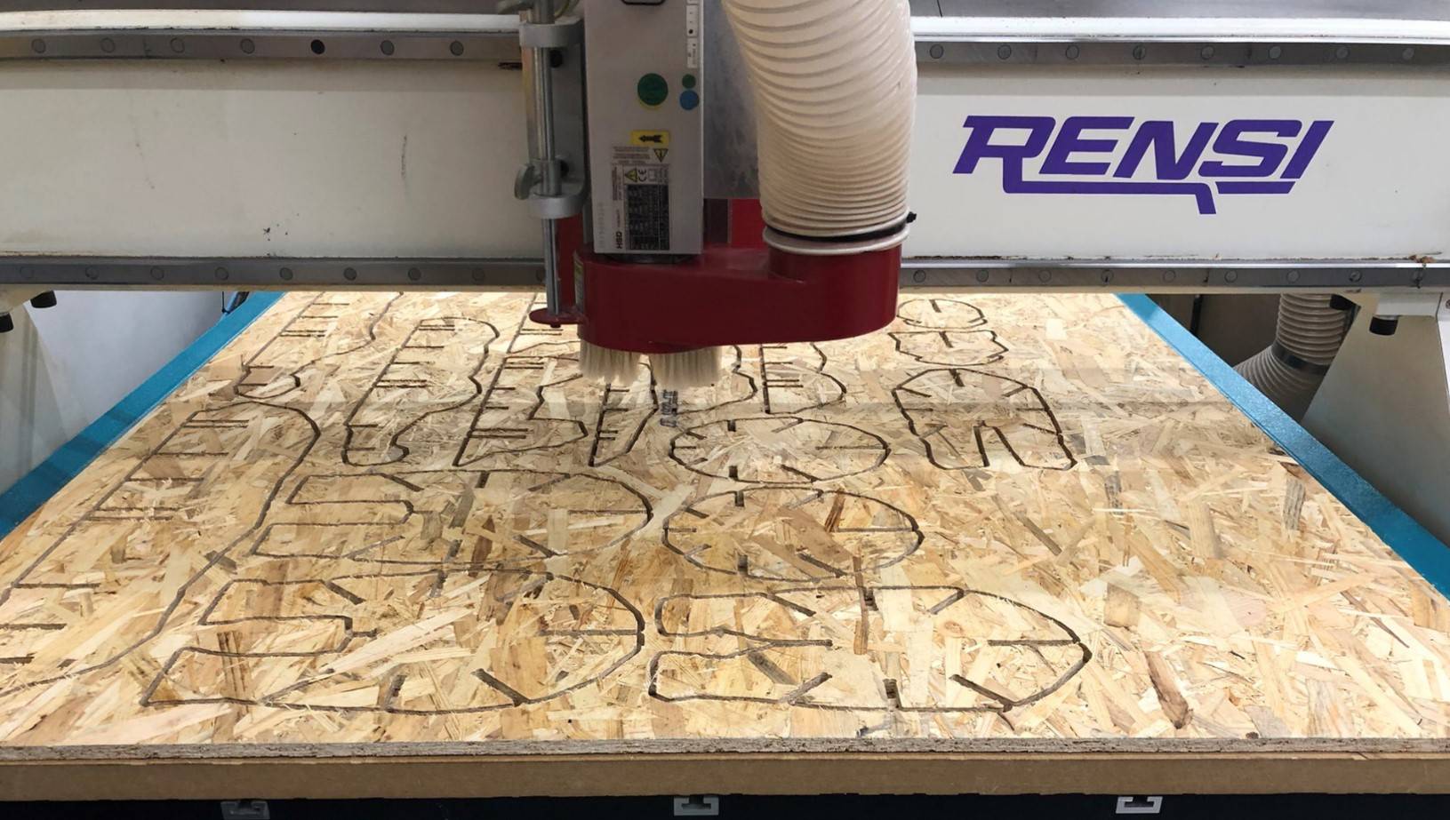
CNC Milling
Step 1: Load and Test file
- File>> Open and Load file >> load nc.file
- Click the Simulation Button to simulate the tool path
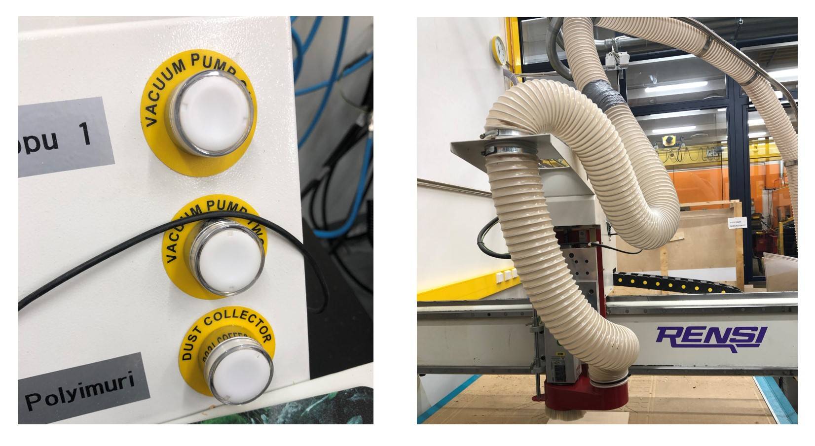
Step 2: Initiate the machine
- Press the dust collector button. The dust collector is a vacuum tube that attached on top of the milling bit, which can remove the dust as the milling bit moves.
- Set speed and feeds:
Feedrate: 100%
Spindle: 100%
- Press the Start button to initiate the milling process.
The entire milling process takes roughly 20 - 30 minutes.
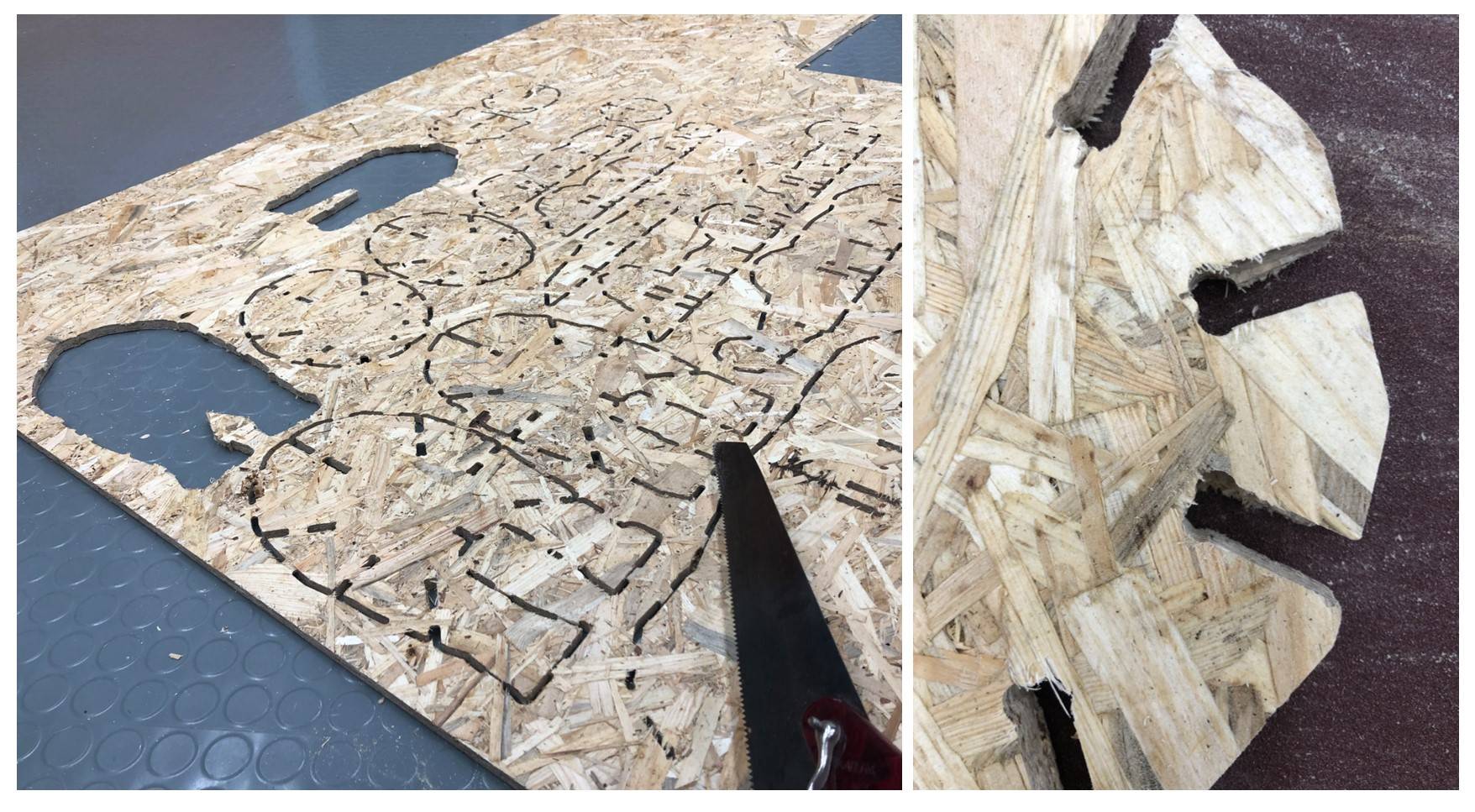
Assembling
After unscrewing the board from the milling platform, use tools like hand saw to cut the tabs and remove the pieces from the board.
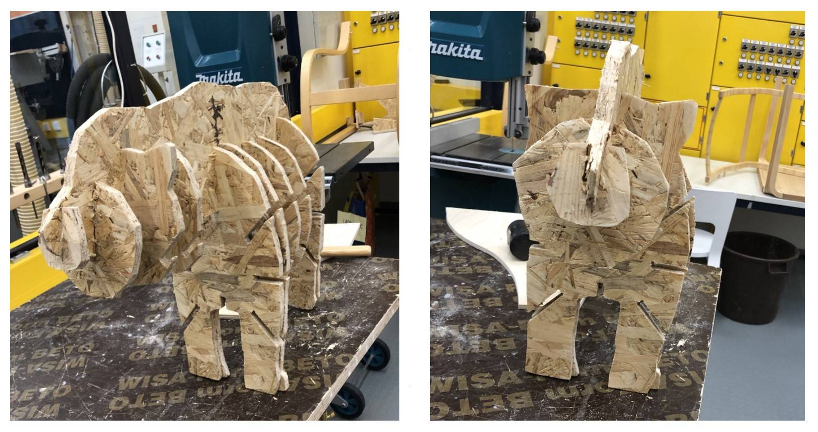
The sand paper machine was not available at the time, so I used sand paper to manually polish the edge of the pieces. Due to the less smooth edges, the assemble process was not easy.
Group Assignment
Please check our Group Assignment Page for more details.
Files
STL FIles:
● Poly Bear
Milling Files:
● NC file
Libraries:
● FabLabCNC.cps ● FabLab Routeri.hsmlib