Individual Assignment
In this week, I decided to simply connect my Arduino UNO board and the microcontroller with an ATTiny412 chip that I made in week 6. This assignment has referred to Jari's archive about this topic.
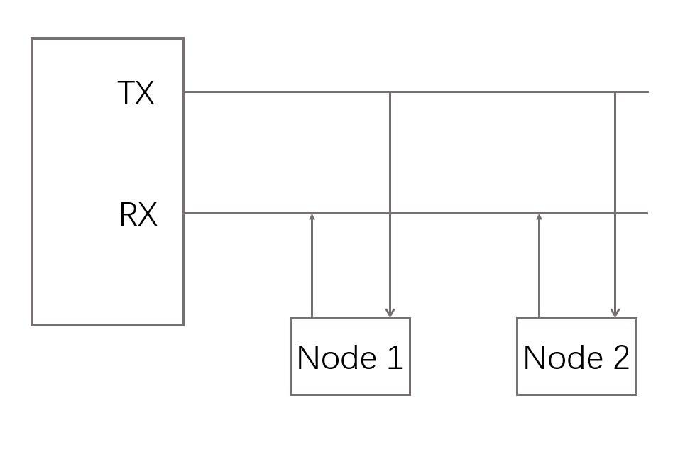
The core mechanism of this type of serial connection is to let the devices share the Tx and Rx input.
Node 1.Arduino Uno board
The first step is to program the Arduino Uno board to response to input node number.
The code are shown as below, which refered to Jari's archive.
a. Code
            #include <SoftwareSerial.h >

            SoftwareSerial mySerial(0, 1); // RX, TX


            const char node = '1'; // network address

            const int ledPin =  13; // the number of the LED pin, which is 13 for UNO board


            int incomingByte;


            void setup() {

              mySerial.begin(9600);

              pinMode(ledPin, OUTPUT);

              pinMode(1, INPUT);

            }


            void loop() {

              if (mySerial.available() > 0) {

                digitalWrite(ledPin, HIGH);

                delay(200);

                digitalWrite(ledPin, LOW);

                delay(200);

                incomingByte = mySerial.read();

                if (incomingByte == node) {

                  digitalWrite(ledPin, HIGH);

                  pinMode(1, OUTPUT); // open line to write

                  mySerial.print("node ");

                  mySerial.println(node);

                  pinMode(1, INPUT);

                  delay(200);

                  digitalWrite(ledPin, LOW);

                }

              }

            }
b.Upload
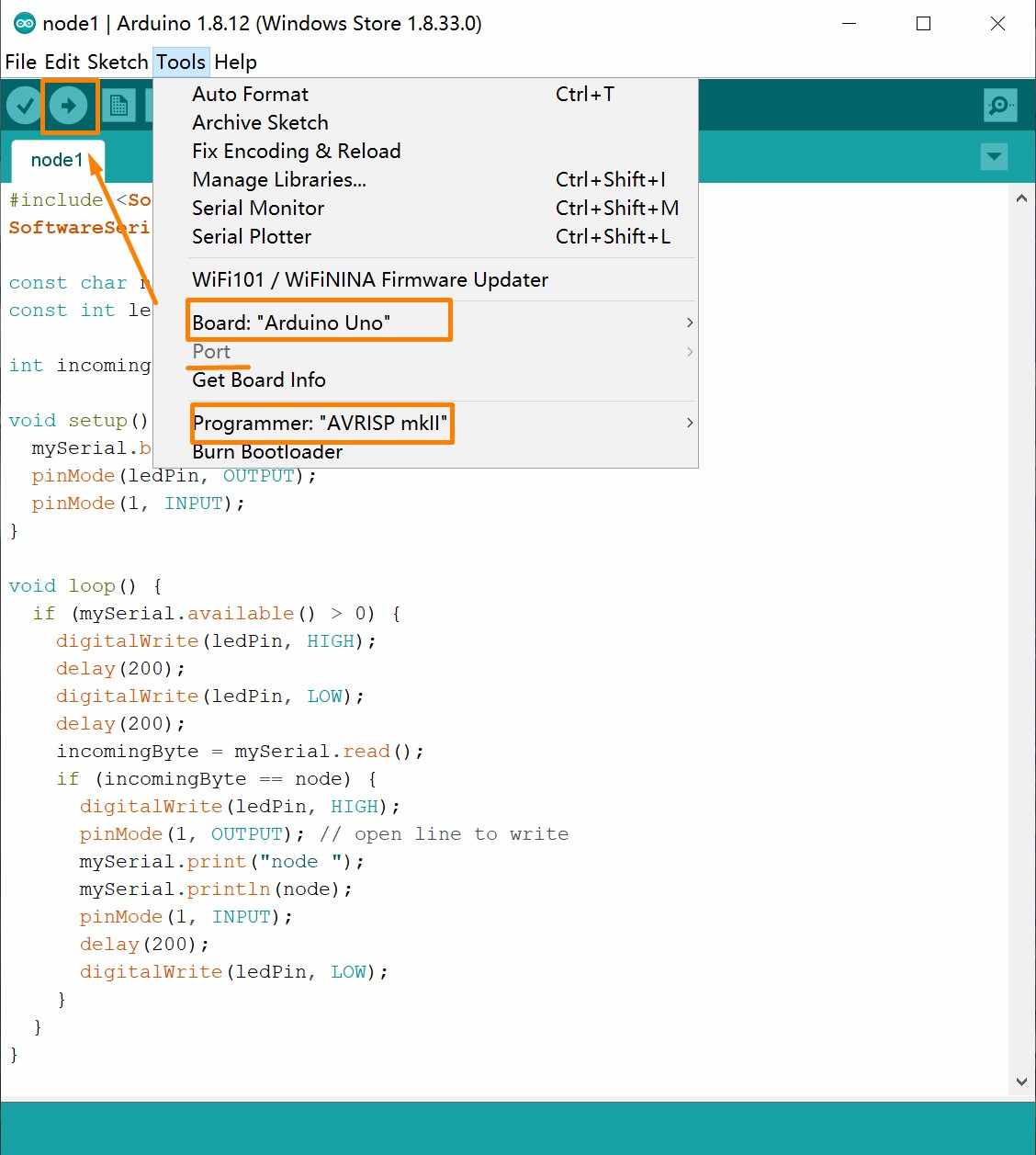
In my case, I used the USB cable to connect the Arduino UNO board to the computer.
Tool>>Board: Arduino UNO >>Port: [COM #]>>Programmer: AVRISP mkll>>Upload
Node 2. ATTiny 412 Board
The second step is to program the microcontroller with an ATTiny412.
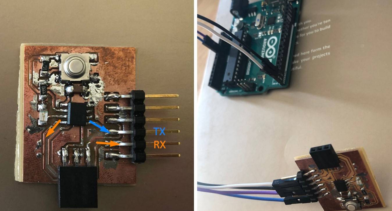
a.Determine connection
This board will be connected to the computer via the Arduino Board, so determining the right Pins to wire is an important procedure.
In my case, there are two sets of pincode mapping: (1) between ATTiny and the board and (2) between the board and UNO. Thus, both the ATTiny chip pin structure and how it is connected to the board need to be specified.
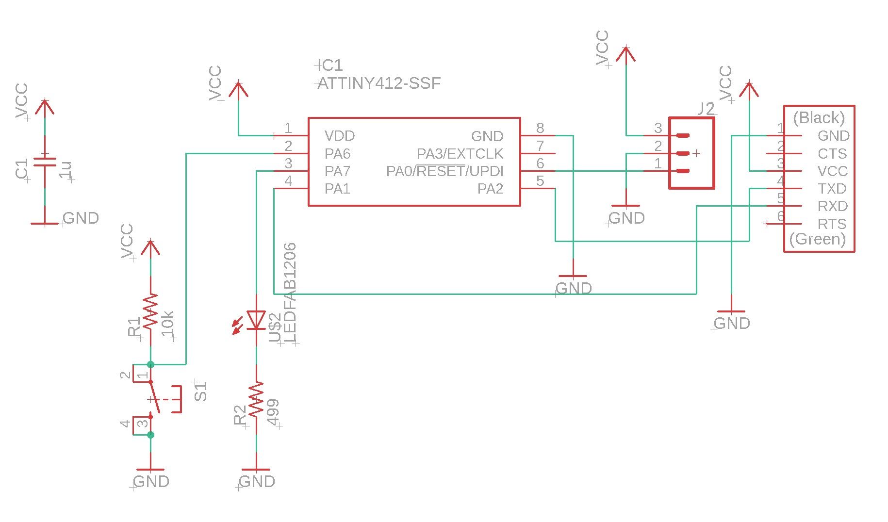
Based on the structures, in my case, the mapping between the Pins should be:
● GND: ATTiny412 Pin 8 - Board Pin 1 -UNO GND
● VCC: ATTiny412 Pin 0 - Board Pin 3 - UNO 5V
● TX : ATTiny412 Pin 3 - Board Pin 4 - UNO 1(TX)
● RX : ATTiny412 Pin 4 - Board Pin 5 - UNO 0 (RX)
It is important to notice that difference between ATTiny Pin number and the board Pin number. I mistakenly used the board Pin number at first and get really strange outcomes.
b. Code
After determining the Pin number, the code for node 2 can be easily revised from the code of node 1.
            #include <SoftwareSerial.h>

                SoftwareSerial mySerial(2,3); // RX, TX (The ATTiny Pin number, NOT the board Pin number)


            const char node = '2'; // network address

            const int ledPin = 1;  // the number of the LED pin


            int incomingByte;


            void setup() {

              mySerial.begin(9600);

              pinMode(ledPin, OUTPUT);

              pinMode(3, INPUT);

            }


            void loop() {

              if (mySerial.available() > 0) {

                digitalWrite(ledPin, HIGH);

                delay(200);

                digitalWrite(ledPin, LOW);

                delay(200);

                incomingByte = mySerial.read();

                if (incomingByte == node) {

                  digitalWrite(ledPin, HIGH);

                  pinMode(3, OUTPUT); // open line to write

                  mySerial.print("node ");

                  mySerial.println(node);


                  pinMode(3, INPUT);

                  delay(200);

                  digitalWrite(ledPin, LOW);

                }

              }

            }
c.Upload and Connect
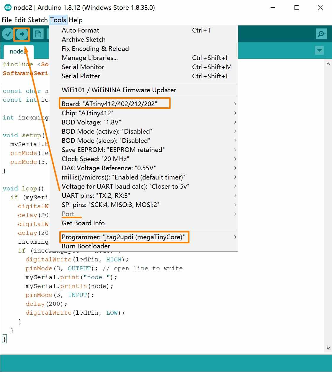
By connecting the board with USB cable, we can upload the code to the board.
Tool>>Board: ATTiny412... >>Port: [COM #]>>Programmer: >>Upload
Then, the USB cable should be removed and the board should be connected to the UNO board with jump wires.
● GND: Board Pin 1/ATTiny Pin 8 -> UNO GND
● VCC: Board Pin 3/ATTiny Pin 0 -> UNO 5V
● RX: Board Pin 5/ATTiny Pin 3 -> UNO 0
● TX: Board Pin 4/ATTiny Pin 4 -> UNO 1
Serial Communication
When the boards are connected to the computer, they are ready to be tested either with Arduino IDE or PuTTY.
I used the Arduino IDE Serial Monitor which can be evoked by clicking the icon the right-top corner.
By typing in the node number, the console will display the node name and the LED on the corresponding board will blink.
The communication part of the final project, which will involve the communication between mobile devices via Wi-Fi, will be updated when finished.
Networking and Communication in Final Project
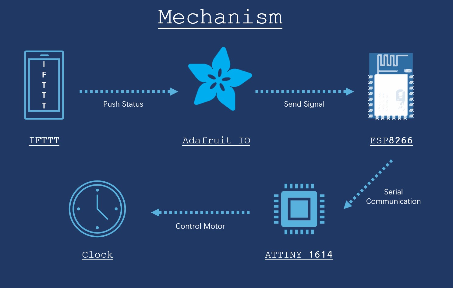
Networking and communication has been an essential part for my final project, which is a clock that can automatically track the location change and inform the family members. There are two major lines of work in this process: (1) The Wi-Fi communication based on ESP8266 and (2)Serial Communication between ESP8266 and ATtiny 1614 controller.
ESP8266 Communication
The logic of this communication is straightforward, which is to acquire the GPS location from the mobile phone and then send the information to my clock.
ESP8266 serves as the core of this chain of communication:
Mobile Phone -> IF This Then That(IFTTT) ->Adafruit IO -> ESP8266.
This communication method was developed by our instructor Iván in his tutorial. Unlike the other previously available tutorials, this one is very friendly to the users who want to design their own board.
The previously existing tutorials tend to rely on commercial boards, such as Particle Photon or ESP8266 Dev board, which have their own specialized modules in IFTTT. Hence, it is hard to follow those tutorial if the users do not use the same commercial board.
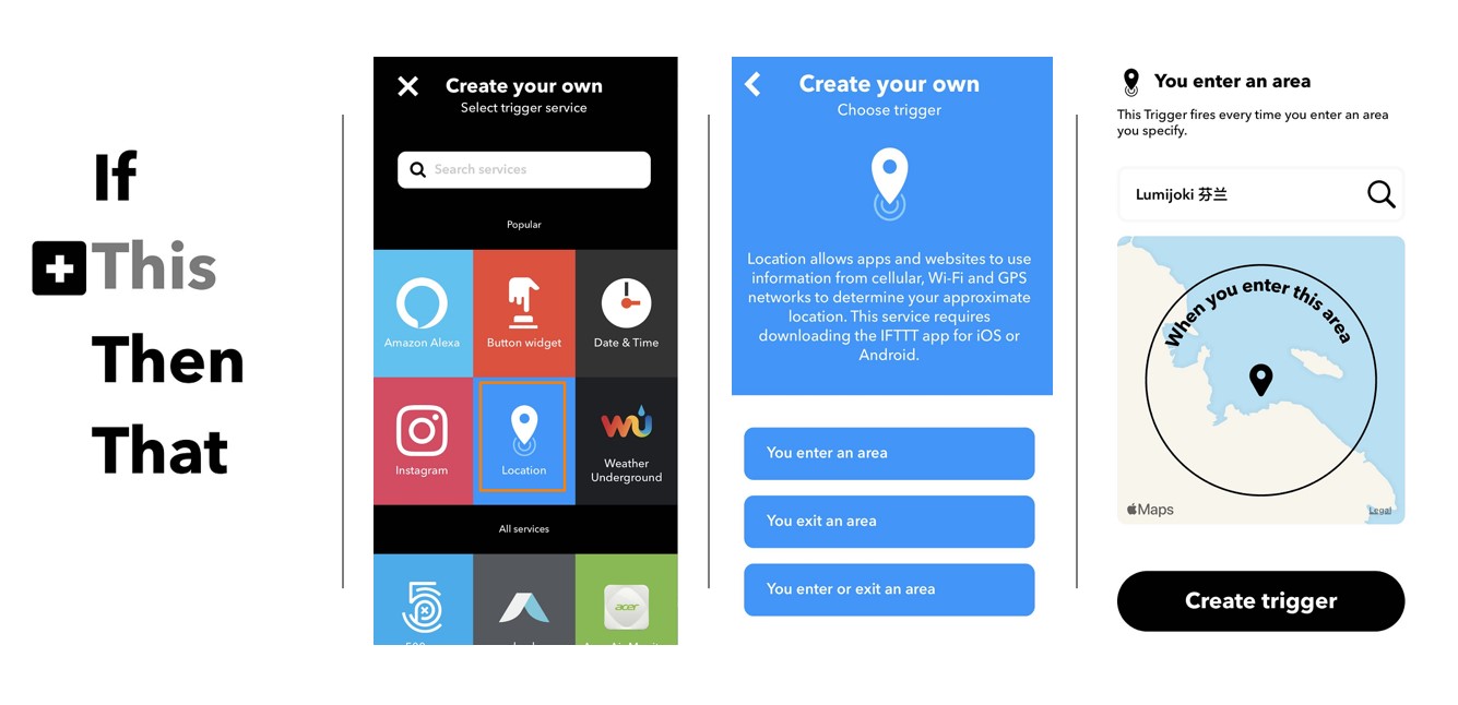
The first step is to create an event with IFTTT which will create a trigger when I enter or leave an area.
1. Click the "+" sign next to "This"
2. Choose "Location" Module
3. Select the action
4. Create Trigger
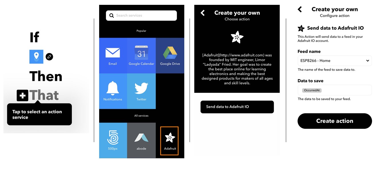
The next step is to push the location change to Adafruit IO.
1. Click the "+" sign next to "That"
2. Choose "Adafruit"
This is where the other tutorials fail to support if the user uses self-made board. Because the commercial boards have their own module, like "Particle".
3. Send Data to Adafruit IO
4. Select the data type
The last step is to send the event to the ESP8266 via Wi-Fi.
The code I used are developed based on Iván's tutorial, which consisted of the a head file and the Wi-Fi communication file.
The major functions of this code include
- Connect to Wi-Fi
#define WIFI_SSID [replace with your own Wi-Fi SSID]
- Connect to Adafruit IO and acquire the trigger
#define WIFI_PASS [replace with your own Wi-Fi Password]
#define IO_USERNAME [replace with your own user name]
- Map each event to a location on the clock
#define IO_KEY [replace with your own user name]
// set up the feed
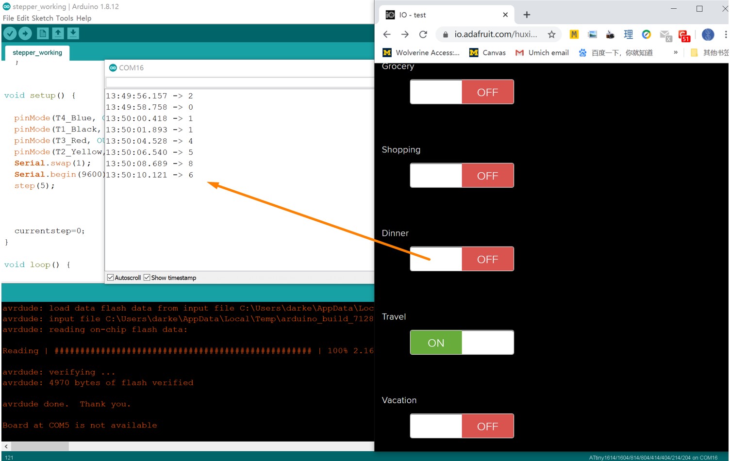
- Print the number that corresponding to the triggered location to the serial port
AdafruitIO_Feed *feed0 = io.feed("Home");
...
void handleMessage1(AdafruitIO_Data *data) {
The full code is as below:
// When received a position
Serial.println("1");//commute
digitalWrite (LED, LOW); // Making LED High.
delay(500); // Some Delay
digitalWrite (LED, HIGH); // Making LED LOW.
}
...
Adafruit_IFTTT_location
// Adafruit IO Subscription Example
//
// Adafruit invests time and resources providing this open source code.
// Please support Adafruit and open source hardware by purchasing
// products from Adafruit!
//
// Written by Todd Treece for Adafru
it Industries
// Copyright (c) 2016 Adafruit Industries
// Licensed under the MIT license.
//
// All text above must be included in any redistribution.
/*
Code written by Iván Sánchez Milara based on example code adafruitio_01_subscribe
Tutorials:
- https://learn.adafruit.com/using-ifttt-with-adafruit-io/
- https://learn.adafruit.com/adafruit-io-basics-esp8266-arduino/
This example code is in public domain.
*************************************************************
This example runs directly on NodeMCU.
Note: This requires ESP8266 support package:
https://github.com/esp8266/Arduino
And the following libraries:
- Adafruit IO Arduino
- Adafruit MQTT library
*************************************************************/
#include <ESP8266WiFi.h>
/************************** Configuration ***********************************/
//const int LED = 2;
// edit the config.h tab and enter your Adafruit IO credentials
// and any additional configuration needed for WiFi, cellular,
// or ethernet clients.
#include "config.h"
// set up the feed
AdafruitIO_Feed *feed0 = io.feed("Home");
AdafruitIO_Feed *feed1 = io.feed("Commute");
AdafruitIO_Feed *feed2 = io.feed("Work");
AdafruitIO_Feed *feed3 = io.feed("School");
AdafruitIO_Feed *feed4 = io.feed("Grocery");
AdafruitIO_Feed *feed5 = io.feed("Shopping");
AdafruitIO_Feed *feed6 = io.feed("Dinner");
AdafruitIO_Feed *feed7 = io.feed("Travel");
AdafruitIO_Feed *feed8 = io.feed("Vacation");
AdafruitIO_Feed *feed9 = io.feed("Neptune");
AdafruitIO_Feed *feed10 = io.feed("Emergent");
AdafruitIO_Feed *feed11 = io.feed("Exercise");
#define delay_time 500
const int LED=2;
void setup()
{
pinMode (LED, OUTPUT);
// start the serial connection
Serial.begin(9600);
// wait for serial monitor to open
while(! Serial);
//Serial.print("Connecting to Adafruit IO");
// start MQTT connection to io.adafruit.com
io.connect();
// set up a message handler for the count feed.
// the handleMessage function (defined below)
// will be called whenever a message is
// received from adafruit io.
feed0->onMessage(handleMessage0);
feed1->onMessage(handleMessage1);
feed2->onMessage(handleMessage2);
feed3->onMessage(handleMessage3);
feed4->onMessage(handleMessage4);
feed5->onMessage(handleMessage5);
feed6->onMessage(handleMessage6);
feed7->onMessage(handleMessage7);
feed8->onMessage(handleMessage8);
feed9->onMessage(handleMessage9);
feed10->onMessage(handleMessage10);
feed11->onMessage(handleMessage11);
// wait for an MQTT connection
// NOTE: when blending the HTTP and MQTT API, always use the mqttStatus
// method to check on MQTT connection status specifically
// while(io.mqttStatus() < AIO_CONNECTED) {
//Serial.print(".");
digitalWrite (LED, HIGH); // Making LED High.
delay(500); // Some Delay
digitalWrite (LED, LOW); // Making LED LOW.
delay(500);
//delay(500);
// }
// Because Adafruit IO doesn't support the MQTT retain flag, we can use the
// get() function to ask IO to resend the last value for this feed to just
// this MQTT client after the io client is connected.
feed0->get();
feed1->get();
feed2->get();
feed3->get();
feed4->get();
feed5->get();
feed6->get();
feed7->get();
feed8->get();
feed9->get();
feed10->get();
feed11->get();
// we are connected
//Serial.println();
//Serial.println(io.statusText());
digitalWrite (LED, LOW); // Making LED High.
}
void loop()
{
// io.run(); is required for all sketches.
// it should always be present at the top of your loop
// function. it keeps the client connected to
// io.adafruit.com, and processes any incoming data.
io.run();
// Because this sketch isn't publishing, we don't need
// a delay() in the main program loop.
}
// this function is called whenever a 'feed' message
// is received from Adafruit IO. it was attached to
// the counter feed in the setup() function above.
void handleMessage0(AdafruitIO_Data *data) {
// When received a position
Serial.println("0");//home
digitalWrite (LED, LOW); // Making LED High.
delay(500); // Some Delay
digitalWrite (LED, HIGH); // Making LED LOW.
}
void handleMessage1(AdafruitIO_Data *data) {
// When received a position
Serial.println("1");//commute
digitalWrite (LED, LOW); // Making LED High.
delay(500); // Some Delay
digitalWrite (LED, HIGH); // Making LED LOW.
}
void handleMessage2(AdafruitIO_Data *data) {
// When received a position
Serial.println("2");//work
digitalWrite (LED, LOW); // Making LED High.
delay(500); // Some Delay
digitalWrite (LED, HIGH); // Making LED LOW.
}
void handleMessage3(AdafruitIO_Data *data) {
// When received a position
Serial.println("3"); //school
digitalWrite (LED, LOW); // Making LED High.
delay(500); // Some Delay
digitalWrite (LED, HIGH); // Making LED LOW.
}
void handleMessage4(AdafruitIO_Data *data) {
// When received a position
Serial.println("4");//grocery
digitalWrite (LED, LOW); // Making LED High.
delay(500); // Some Delay
digitalWrite (LED, HIGH); // Making LED LOW.
}
void handleMessage5(AdafruitIO_Data *data) {
// When received a position
Serial.println("5");//shopping
digitalWrite (LED, LOW); // Making LED High.
delay(500); // Some Delay
digitalWrite (LED, HIGH); // Making LED LOW.
}
void handleMessage6(AdafruitIO_Data *data) {
// When received a position
Serial.println("6");//dinner
digitalWrite (LED, LOW); // Making LED High.
delay(500); // Some Delay
digitalWrite (LED, HIGH); // Making LED LOW.
}
void handleMessage7(AdafruitIO_Data *data) {
// When received a position
Serial.println("7");//travel
digitalWrite (LED, LOW); // Making LED High.
delay(500); // Some Delay
digitalWrite (LED, HIGH); // Making LED LOW.
}
void handleMessage8(AdafruitIO_Data *data) {
// When received a position
Serial.println("8");//vacation
digitalWrite (LED, LOW); // Making LED High.
delay(500); // Some Delay
digitalWrite (LED, HIGH); // Making LED LOW.
}
void handleMessage9(AdafruitIO_Data *data) {
// When received a position
Serial.println("9");//Neptune
digitalWrite (LED, LOW); // Making LED High.
delay(500); // Some Delay
digitalWrite (LED, HIGH); // Making LED LOW.
}
void handleMessage10(AdafruitIO_Data *data) {
// When received a position
Serial.println("10");//emergent
digitalWrite (LED, LOW); // Making LED High.
delay(500); // Some Delay
digitalWrite (LED, HIGH); // Making LED LOW.
}
void handleMessage11(AdafruitIO_Data *data) {
// When received a position
Serial.println("11");//exercise
digitalWrite (LED, LOW); // Making LED High.
delay(500); // Some Delay
digitalWrite (LED, HIGH); // Making LED LOW.
}
config.h
/************************ Adafruit IO Config *******************************/
// visit io.adafruit.com if you need to create an account,
// or if you need your Adafruit IO key.
                        #define IO_USERNAME [replace with your own user name]

                        #define IO_KEY [replace with your own user name]
// Add the name of the feed you want to connect to
//#define IO_FEED_NAME "Home"
/******************************* WIFI **************************************/
// the AdafruitIO_WiFi client will work with the following boards:
// - HUZZAH ESP8266 Breakout -> https://www.adafruit.com/products/2471
// - Feather HUZZAH ESP8266 -> https://www.adafruit.com/products/2821
// - Feather HUZZAH ESP32 -> https://www.adafruit.com/product/3405
// - Feather M0 WiFi -> https://www.adafruit.com/products/3010
// - Feather WICED -> https://www.adafruit.com/products/3056
// - Adafruit PyPortal -> https://www.adafruit.com/product/4116
// - Adafruit Metro M4 Express AirLift Lite ->
// https://www.adafruit.com/product/4000
// - Adafruit AirLift Breakout -> https://www.adafruit.com/product/4201
// - Adafruit AirLift Shield -> https://www.adafruit.com/product/4285
// - Adafruit AirLift FeatherWing -> https://www.adafruit.com/product/4264
#define WIFI_SSID [replace with your own Wi-Fi SSID]
#define WIFI_PASS [replace with your own Wi-Fi Password
]
// uncomment the following line if you are using airlift
// #define USE_AIRLIFT
// uncomment the following line if you are using winc1500
// #define USE_WINC1500
// comment out the following lines if you are using fona or ethernet
#include "AdafruitIO_WiFi.h"
#if defined(USE_AIRLIFT) || defined(ADAFRUIT_METRO_M4_AIRLIFT_LITE) ||
\
defined(ADAFRUIT_PYPORTAL)
// Configure the pins used for the ESP32 connection
#if !defined(SPIWIFI_SS) // if the wifi definition isnt in the board variant
// Don't change the names of these #define's! they match the variant ones
#define SPIWIFI SPI
#define SPIWIFI_SS 10 // Chip select pin
#define NINA_ACK 9 // a.k.a BUSY or READY pin
#define NINA_RESETN 6 // Reset pin
#define NINA_GPIO0 -1 // Not connected
#endif
AdafruitIO_WiFi io(IO_USERNAME, IO_KEY, WIFI_SSID, WIFI_PASS, SPIWIFI_SS,
NINA_ACK, NINA_RESETN, NINA_GPIO0, &SPIWIFI);
#else
AdafruitIO_WiFi io(IO_USERNAME, IO_KEY, WIFI_SSID, WIFI_PASS);
#endif
/******************************* FONA **************************************/
// the AdafruitIO_FONA client will work with the following boards:
// - Feather 32u4 FONA -> https://www.adafruit.com/product/3027
// uncomment the following two lines for 32u4 FONA,
// and comment out the AdafruitIO_WiFi client in the WIFI section
// #include "AdafruitIO_FONA.h"
// AdafruitIO_FONA io(IO_USERNAME, IO_KEY);
/**************************** ETHERNET ************************************/
// the AdafruitIO_Ethernet client will work with the following boards:
// - Ethernet FeatherWing -> https://www.adafruit.com/products/3201
// uncomment the following two lines for ethernet,
// and comment out the AdafruitIO_WiFi client in the WIFI section
// #include "AdafruitIO_Ethernet.h"
// AdafruitIO_Ethernet io(IO_USERNAME, IO_KEY);
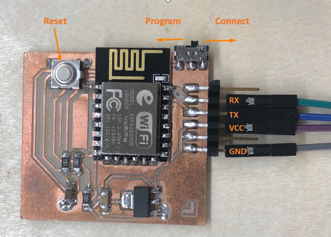
My design of the ESP8266 contains a slide switch that has a program position and a connect position. The slide switch should be turned to the program position when uploading the code. After the code is successfully uploaded, turn the slide switch to the connect position and press the reset button, then the ESP8266 board is ready to be used.
When the ESP8266 board is connected, it can receive te push from the Adafruit IO system.
For test and demonstration purposes, I have used the Adafruit IO dashboard to simulate the location change. When the event is turned ON and OFF the corresponding numbers are printed into the serial port.
ESP8266-ATtiny 1614 Serial Communication
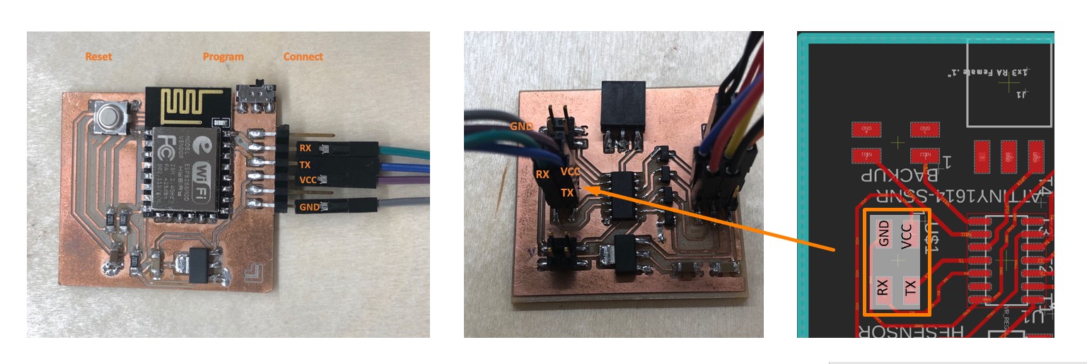
The ESP8266 board and ATTINY 1614 board should have these pins connected in this way:
●VCC - VCC
●GND - GND
●TX - TX
●RX - RX
The numbers of triggered event is then send from the ESP8266 board to the ATtiny 1614 microcontroller, which then drives the motor to move to the corresponding postions.
The critical code to achieve this goal is as below:
The code in the void loop() reads the serial input from ESP8266. As the Serial.Read() function reads single byte in ASCII format, the input information needs to be further processed to let the ATtiny 1614 to receive the actual numbers.
moveToLocation() function is the actual code that drives the motor.
More details about the code can be found here.
Critical Episodes of the Code
             //Move to position

                void moveToLocation(int location){

                  num_of_steps = (location - current_location)*4; // Each location is 30 degrees. You have then 4 steps per locations


                  current_location = location;

                 Serial.print("steps: ");

                 Serial.println(num_of_steps);

                  step (num_of_steps);

                  }

            ...

            void loop() {


                // put your main code here, to run repeatedly:

                    //for location10, 11 and 12, which are more than 1 byte

                  while (Serial.available()>0) {

                   int inChar = Serial.read();

                    if (isDigit(inChar)) {

                      // convert the incoming byte to a char and add it to the string:

                      inString += (char)inChar;

                    }

                    // if you get a newline, print the string, then the string's value:

                    if (inChar == '\n') {

                      //Serial.print("Value:");

                      int location = inString.toInt();

                      inString = "";//

                ...

                }

                    }

                    }
Group Assignment
This week's group assignment is to send a message between two projects。 Our group used 3 ATtiny 412 boards that were made in a previous week as different nodes.
In order to more conveniently connect the boards, we referred to Jari's archive and resued his design of Rx/Tx Hub (Trace.rml, Outline.rml).
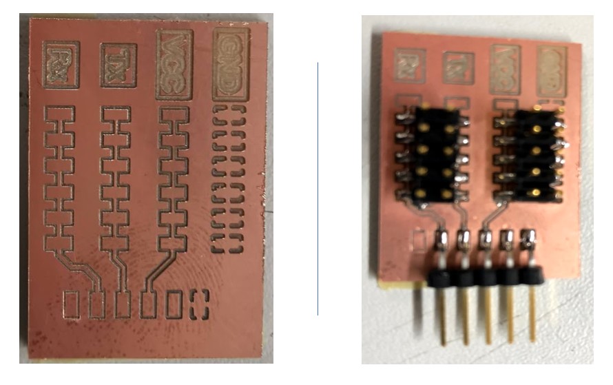
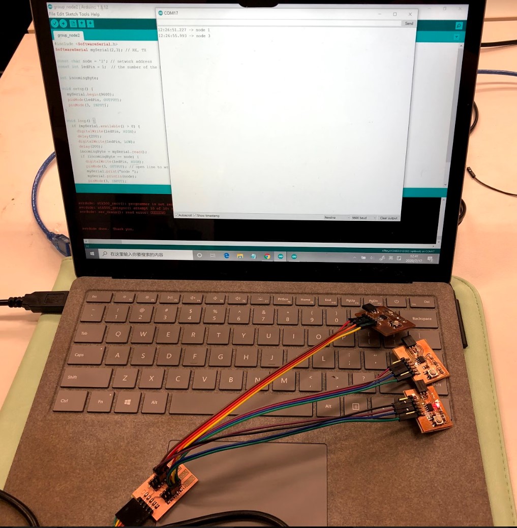
After milling and soldering the hub, we connected the 3 boards with the hub.
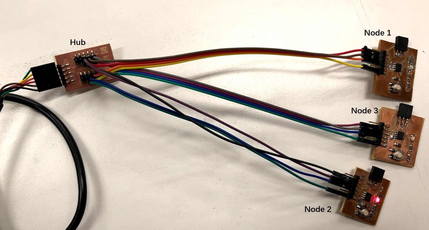
We reused the the code for serial communication, which sends the message several times through the network.
Node Sample
The number after "const char node" has been changed for different nodes.
                #include <SoftwareSerial.h>

                SoftwareSerial mySerial(2,3); // RX, TX (The ATTiny Pin number, NOT the board Pin number)


            const char node = '1'; // network address

            const int ledPin = 1;  // the number of the LED pin


            int incomingByte;


            void setup() {

              mySerial.begin(9600);

              pinMode(ledPin, OUTPUT);

              pinMode(3, INPUT);

            }


            void loop() {

              if (mySerial.available() > 0) {

                digitalWrite(ledPin, HIGH);

                delay(200);

                digitalWrite(ledPin, LOW);

                delay(200);

                incomingByte = mySerial.read();

                if (incomingByte == node) {

                  digitalWrite(ledPin, HIGH);

                  pinMode(3, OUTPUT); // open line to write

                  mySerial.print("node ");

                  mySerial.println(node);


                  pinMode(3, INPUT);

                  delay(200);

                  digitalWrite(ledPin, LOW);

                }

              }

            }
Files
Arduino Code:
Individual: ● Place holder ● Place holder
Group: ● Analog Detection