Group Assignment
In this week, as a group, we are going to design a machine that includes mechanism, actuation, and automation features.
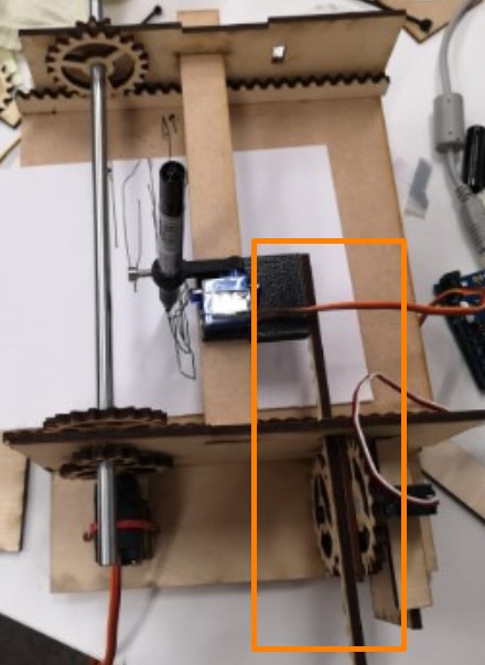
The full group documentation can be retrieved from this machine design group assignment page.Our group designed and created a servo-motor-based drawing machine. Our project refers to this tutorial. We have expanded the scope of this project and make the machine twice in size comparing to the tutorial, which left us with a many effort in modification of the part sizes.
In this week, our group worked closely with each other and finished many works together. I have majorly taken the work related to the gear modification.
Gear Track
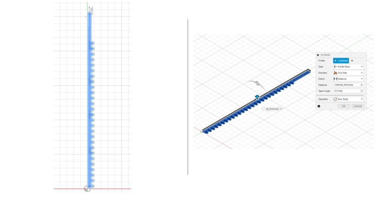
I started the modification with the gear track, because it involves more parametric matching than the gears. This gear track is attached to the pen holder platform, which allows the pen to move horizontally across the paper.
In order to be compatible with other part, I retained the the shape of the track from the tutorial and enlarged the shape to twice as the orginal size. After ensuring the contour have been well connected, the track is extruded for 4mm (material_thickness).
For convenience, I have set the material thickness to 4mm so it will be easier for making further modfication if we want to change the material later.
Gears
There are three types of gears used in this project.
Some gear calculation basic knowledge and formula can be found at:this tutorial

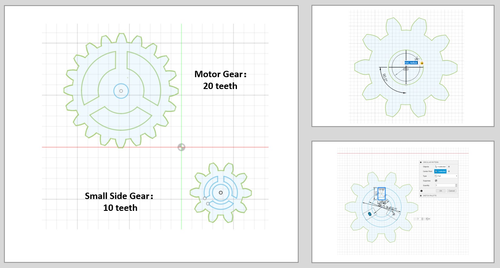
A. Motor Gears x 3
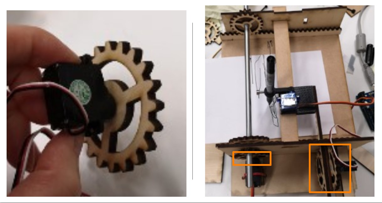
Three gears are attached to the motors for motion transmission.
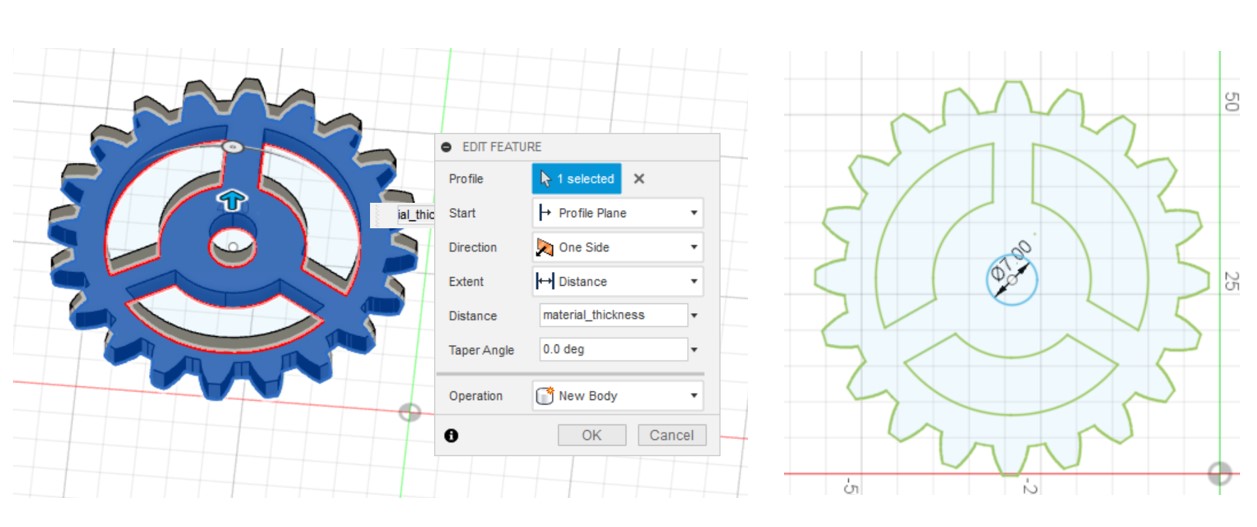
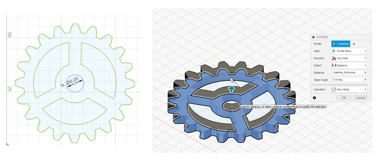
The motor gears have 20 gear teeth and have a inner slot diameter as 7 mm, which is determined by the diameter of the motor gear.
The gear sketch is extruded by 4mm.
B. Small Side Gear x2
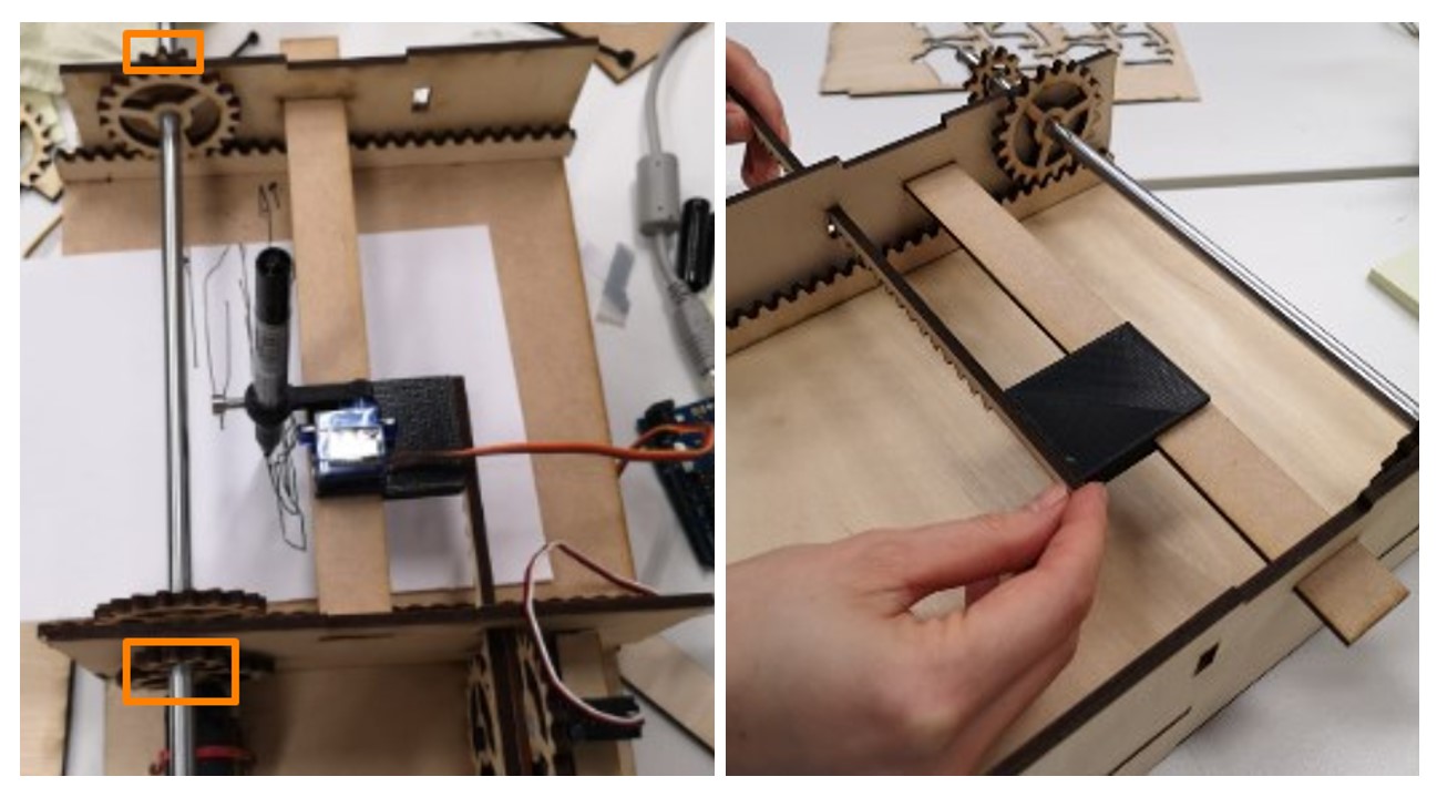
Two small side gears are attached to the same rod as the large side gears, which mediate the motion of motor gear and the large gear that drives the paper platform.
The small side gears gears have 10 gear teeth and have a inner slot diameter as 8 mm, which is determined by the diameter of the rod used to connect large and small side gears.
C. Large Side Gear x 2
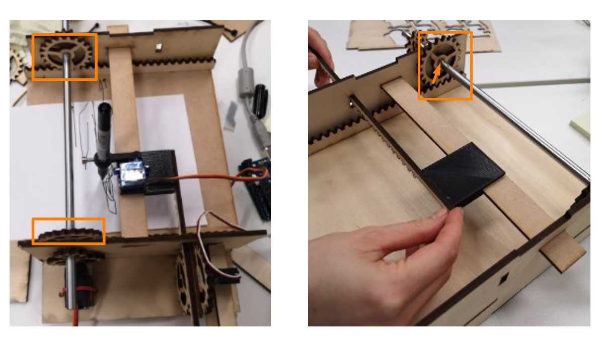
There are two large side gears that is used to drive the paper platform to move back and forth. Both large and small side gears are firmly attached to the rod, so the small side gear can transfer the motion from the motor gear to the large side gear.
The large side gears gears have 20 gear teeth and have a inner slot diameter as 8 mm, which is determined by the diameter of the rod used to connect large and small side gears.
After adjusting the parameters, the gear sketch is extruded by 4mm.
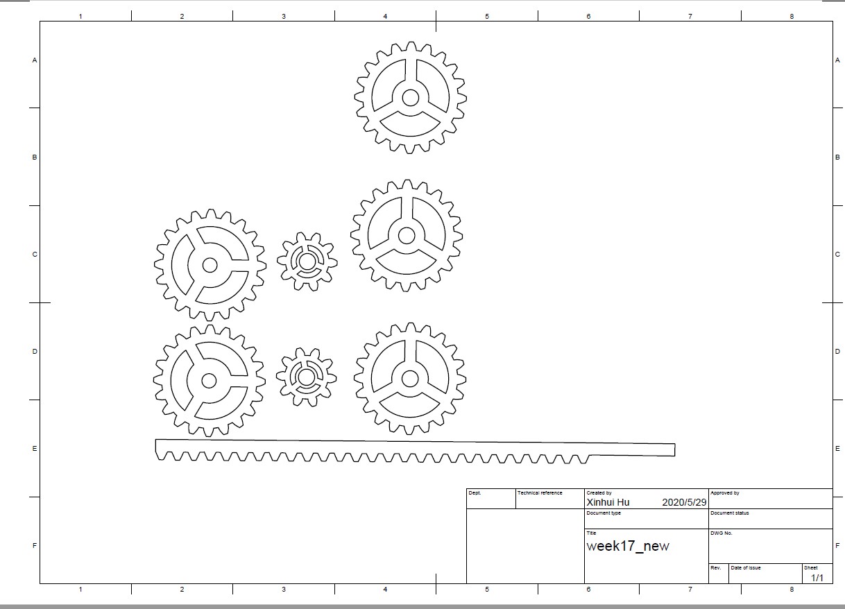
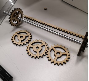
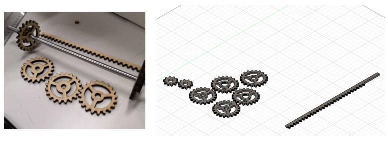
The next step is to laser cut or 3D print the parts, in this case, I have chosen laser cutting.
Draw >> Create from Design >> Export PDF will allow the sketch to be exported for laser cutting. After trimming the irrelevant lines and rearranging the layout, the gears and tracks can be manufactured.