Drawing machine
Group members
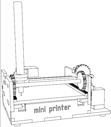
Sketch
Our idea is to make a drawing machine inspired by this Printing Machine
List of components:
| Component | Qty | Function | Production |
|---|---|---|---|
| SG-90 Servo motors | 3 | Moving the platform (Y), Pen height adjustment, Pen carriage positioning (X) | Fablab inventory |
| Gears (2 types) | 1 | Z axis pen positioning | Laser cutting |
| Gear holder and 2 servo holders | 2 | Laser cutting | |
| Aluminium rod | 1 | Combined with 2 gears moving the stage | Fablab inventory |
| Motor mounts | 2 | Fixing the positions of the motors | 3D printing |
| Geared rails | 3 | 2 to move the stage (Y), 1 to move the pen carriage (X) | Laser cutting |
| Pen holder | 1 | 3D printed with a bolt screw M3 | 3D printing |
| Arduino Uno board | 1 | Controlling the system | Fablab inventory |
| Carcass | 1 | Mount for all the components: 1 Bottom, 2 Sides, 3 Front hold, 2 Rails | Laser cutting |
| Pen | 1 | Drawing | Shop |
| Glue | 1 | Shop |
Roles and responsibilities
-
Zhengya: Designing the drawing box and files for laser cutter, laser cutting
-
Xinhui: Laser cutting, assembling of the cut parts, 3D printing (designing and printing of the gears)
-
Noora: Documentation, making and updating the project page, designing the pen holder
-
Yazan: Coding
-
Tatiana: Making components list, design and printing of the pen holder, assembling
Machine parts
We used laser cutter and 3D printer to make the parts. The machine body files were modified using Fusion 360 to make finger joints to make it easier to assembly the machine parts together.

Laser cutter kerf was taken into account in the design to make it possible to fit the laser cut parts together. The laser cutter bed was set to right height using fixing tool and 4mm Plywood settings were used in Epilog Engraver program.

We decided to make the pen holder using 3D printer. Pen diameter was 11.23 mm and servo's axis point diameter was 4.58 mm. These dimension were used to make the holder. The part was printed from ABS and the end result worked well: the pen height can be fixed with the screw.


Assembly and testing
After laser cutting the machine body the parts were assembled together. We used glue to fix the parts together.


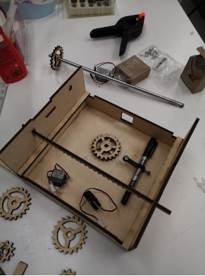


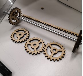
Gears were fixed to aluminium rod and servo and assembled to the body.
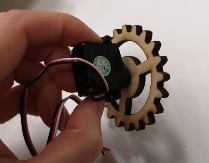
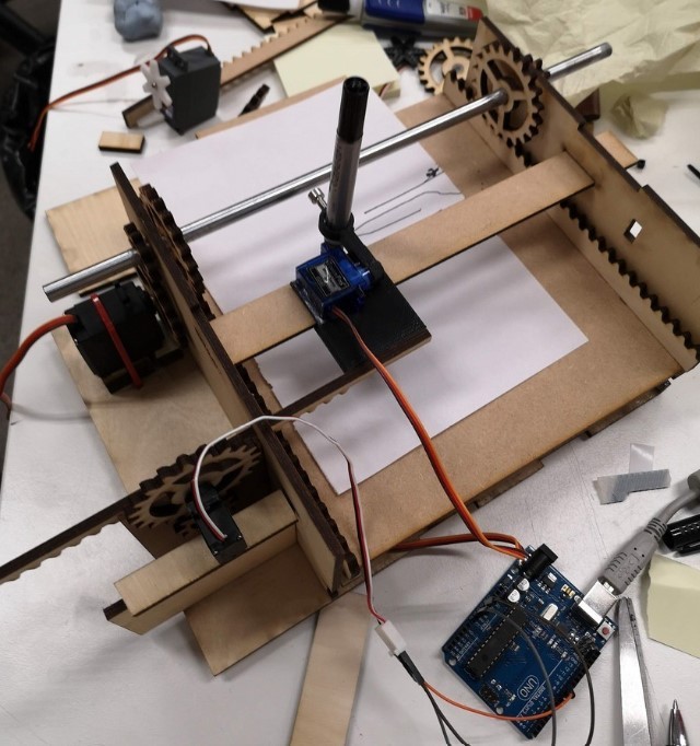
We checked that servo worked in this assembly by connecting it to Arduino.
The other servo is fixed to move the pen holder. The assembly is again checked using Arduino.
Next the pen holder is fixed to right position and servo attached to pen holder is tested using Arduino.

Coding
The Servos can be connected to the Arduino Uno. The 1st motor is connected to pin2, the 2nd to pin4, and the 3rd to pin6.
Then, the following sketch was uploaded.
#include <Servo.h>
// Motor structs ..

// angles and an instance of the Servo class
struct Motor
{
  int min_angle, max_angle;
  Servo servo;
};

struct Motor motor_x, motor_y, motor_p;
struct Motor newMotor (int pin, int a1, int a2)
{
  // Initialize the motor
  struct Motor m;
  m.servo.attach (pin);
  m.min_angle = a1;
  m.max_angle = a2;
  return m;
}

void setup () {// Initialization
  Serial.begin(9600);
  motor_y = newMotor(2, 50, 180);
  motor_x = newMotor(4, 30, 160);
  motor_p = newMotor(6, 90, 99);
}

void loop ()
{
  // Drawing ... can be modified for rect...
   motor_p.servo.write (motor_p.max_angle); // Raise the marker
   delay (15);
   // Move to point (0; 0)
   motor_x.servo.write (motor_x.min_angle);
   motor_y.servo.write (motor_y.min_angle);
}
A video showing the machine drawing one line using motor_y.servo.write (motor_y.angle)
A video showing the machine drawing a rectangle using motor_y.servo.write (motor_y.angle) and motor_x.servo.write (motor_x.angle)
Reflection
Even though this drawing machine satisfies the requirements for this week’s assignment, we did have bigger plans for it. The original idea was to draw more than rectangles within an Arduino Environment, but due to time limitation, we did not reach that stage; such drawing machine would have required an interface program that would allow for COM port communication and image processing capabilities e.g., the desired image would have been “pixelated” then mapped to each of the motors accordingly. Hopefully, we will get back to this after FabAcademy!
Files
Archive includes following files
- 3D_file_for_laser_cutting.f3d

- carriage.f3d

- gear.f3d

- PDF_file_for_laser_cutting.pdf

- pen_holder.f3d

- printable.pdf