Individual Assignment
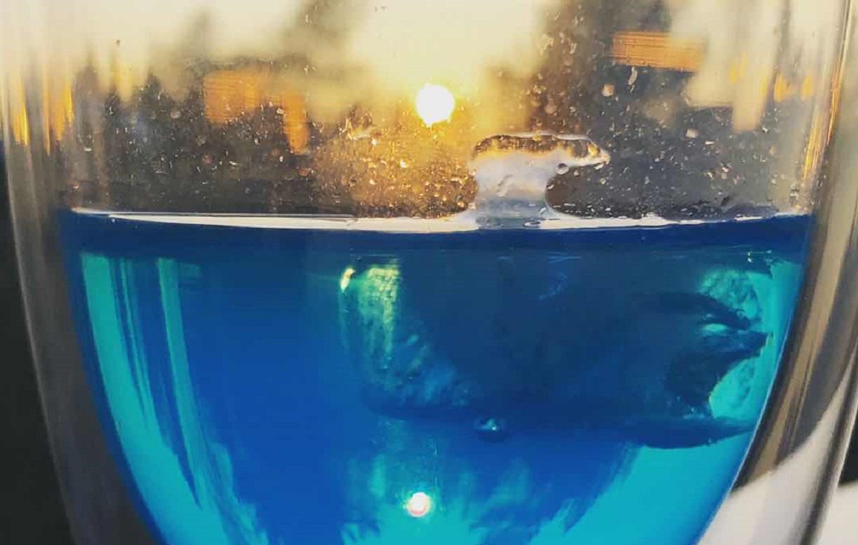
In this week, I would like to make an ice cube mold that shows a polar bear floating on an iceberg. On the one hand, this should be a fun idea for daily usage. On the other hand, while the ice cube is melting, people may be reminded of the environmental problems that polar bears are facing, the melting glaciers, and live in a more eco-friendly way. In this process, I designed the model and the negative molds in Fusion 360 and
Design
Create Components
The design of the mold was accomplished in There are three main components of this ice cube mold design: iceberg,polar bear, and the alignment pins that ensure the two-piece mold can match firmly.
1. Iceberg
After ideation, I decided to make a diamond-shaped iceberg instead of simple cylinder. For flexible adjustment and convenient moving operation, I adopt the parametric design strategy. So the first step is to determine the parameters of this model. I measured the diameters and height of the cups that I usually used and decided the parameters accordingly.
My original strategy was to first create the bear and then the iceberg, but I then found this will induce much more modifications in the later process because this will involve massive alignment works. So I highly recommend starting from the iceberg.
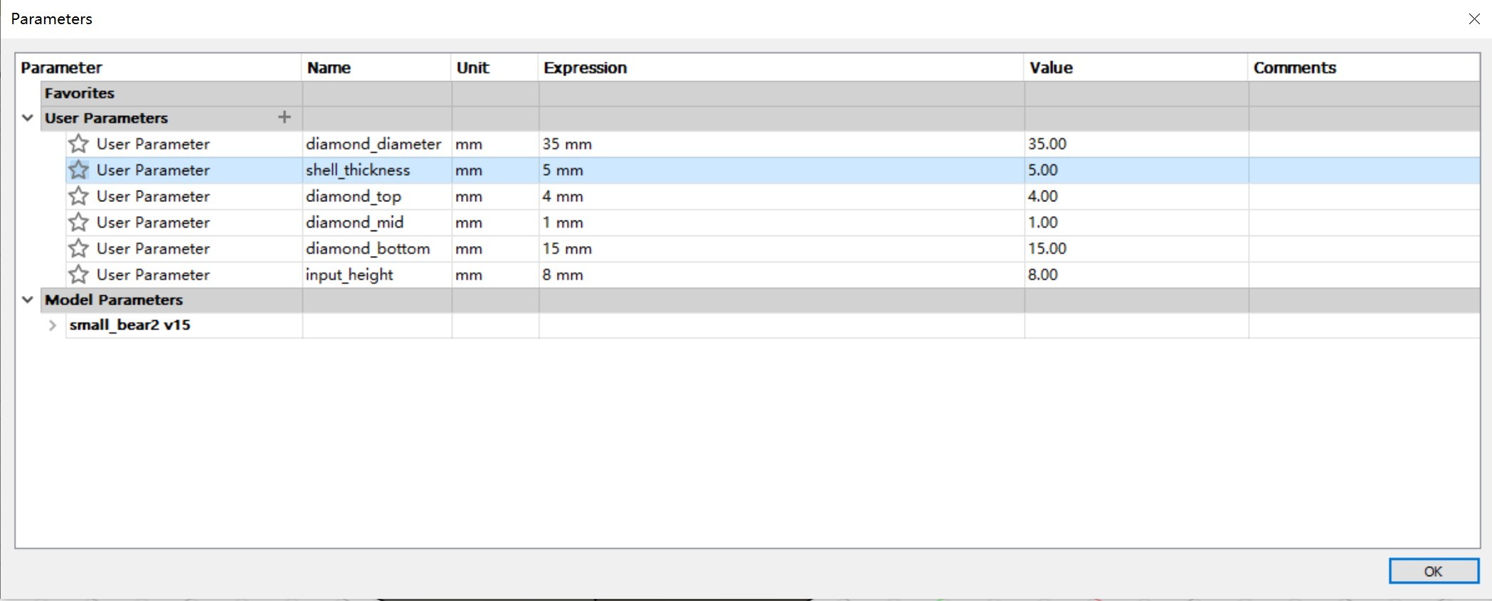
1.1 Middle layer of the diamond
The middle layer of the diamond, which works as the base of other parts, can be created with following simple steps
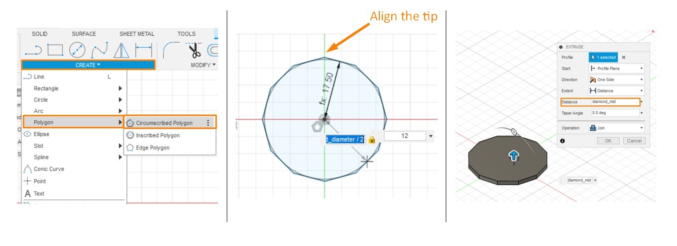
Top Menu >> Create >> Polygon >> Circumscribed Polygon
-Dimension=diamond_diameter/2
-Edge Number = 12
* Aligning the tip of the polygon with the axis is a good idea, which will save much effort in later steps, especially before spilting the model.
Select the Polygon>>Top Menu >> Create>>Extrude
-Distance = diamond_mid
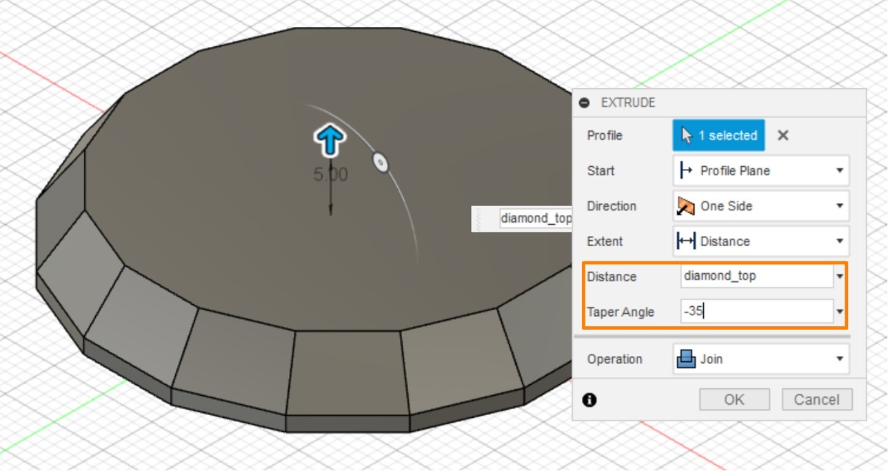
1.2 Top layer of the diamond
Select the top surface of the mid-part of the diamond and adopt the Extrude function with following settings:
Top Menu >> Create >> Extrude
- Distance: diamond_top
- Degree: - 35°
The design of the diamond top can be fancier if it is further faceted. To create new facets on the surface of the diamond, a new plane need to be first defined with following operations:
Top Menu >> Construct >> Plane Through Three Points >> Select three points
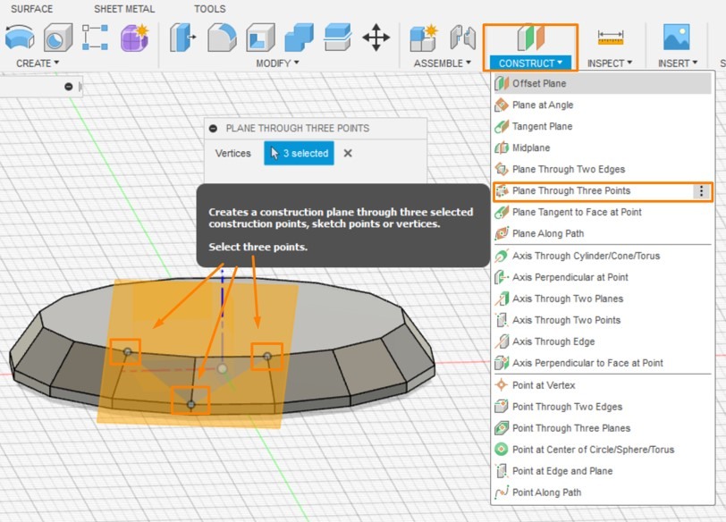
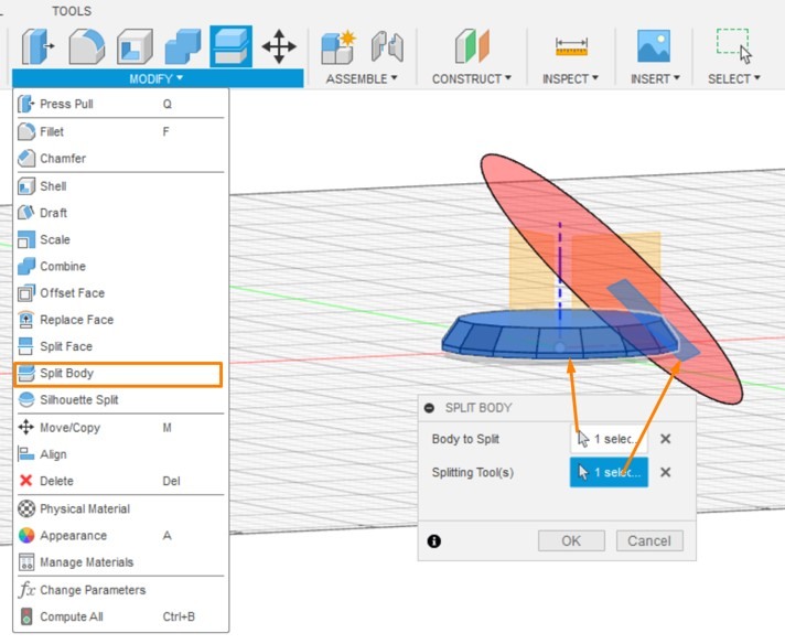
The next step is to create a new facet with Split Body function
Top Menu >> Modify >> Split Body
- body to select: the diamond
- spliting tool(s): the new plane
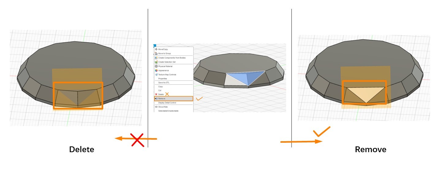
Select the split part, Right click and select Remove, a new facet will be created
It is important to select "Remove" instead of commonly used "Delete" function. Because the latter will not create the new facet.
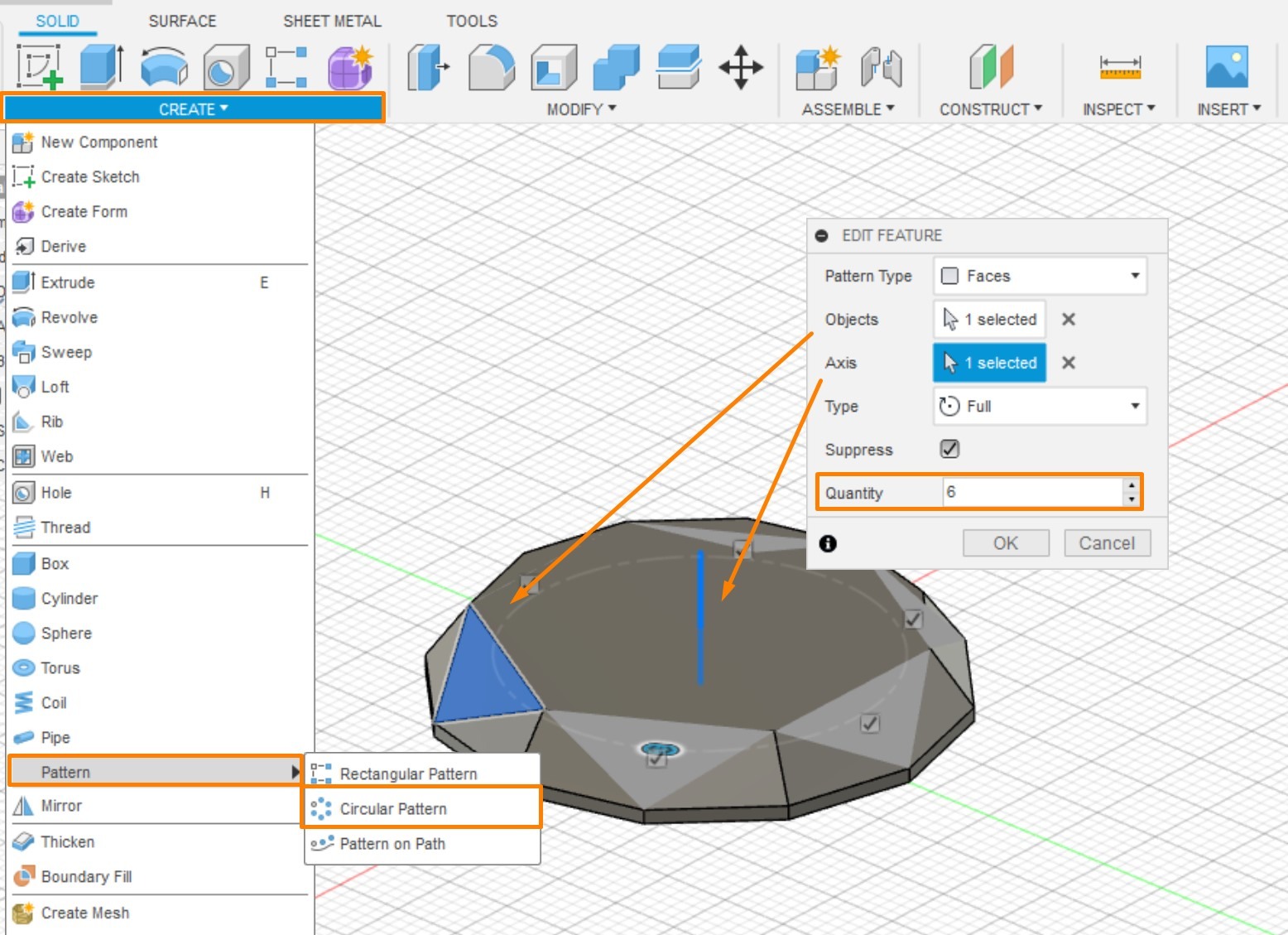
The same procedures are supposed to be repeated for each angle of the diamond, while creating a circular pattern will relieve us from the repetitive works.
Top Menu >> Create >> Pattern >> Circular Pattern
- Pattern type >> Faces
- Object >> Select the new facets
- Axis >> Z
- Quantity >> Edge Number/2
Further extruding the top face of the diamond can make it even fancier. However, in order to leave more spaces for the bear to stand, this model does not include the extra top layer.
1.3 Bottom layer of the Diamond
The bottom part of diamond can be created in exactly the same procedure as the top part.
Select the bottom surface of the diamond's middle layer and apply the Extrude function with these parameters:
Top Menu >> Create >> Extrude
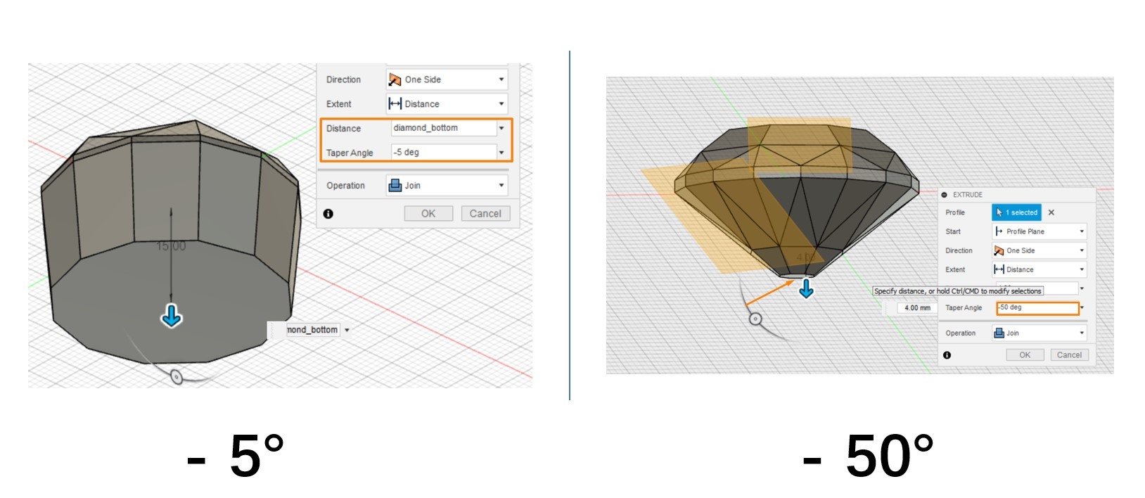
- Distance: diamond_bottom
- Degree: -5°
● For aesthetic preference, the botton part can also be further faceted with the same operations.
● The degree was set to - 5° in this model to ensure there are adequate volume underneath the water and provide adequate buoyancy. For a perfect diamond shape, the proper degree should be -50°.
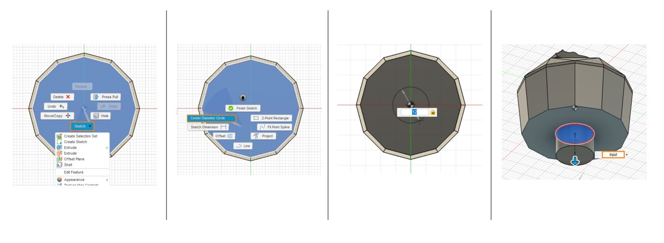
1.4 Input Tunnel
A space for the pouring in the materials should be left at the bottom of the mold.
To ensure the centers of the tunnel and the diamond well-aligned, the base of the tunnel is best created by the Center Diameter Circle funtion.
Select the bottom surface of the diamond and follow the path of Right click >> Sketch >> Center Diameter Circle
-diameter = 12 mm
* I was recommended to set the diameter around 10 mm.
Select the Circle >> Extrude
- distance = input
* The input was set to 8 mm in my case.
2. Bear
The next step is to create the polar bear. I tried both importing an external model and extruding from the silhoutte of a bear and found the latter will be the better strategy. The imported mesh body not only requires additional efforts in scaling and modifying but also brings troubles when spliting the model.
The polar bear silhoutte I used was retrieved from SVG REPO.

Turn the Diamond model to its left or right side and create sketch. In this way, the imported SVG image will automatically share the center with the diamond, which saves the time for modifying the locations and orientations.
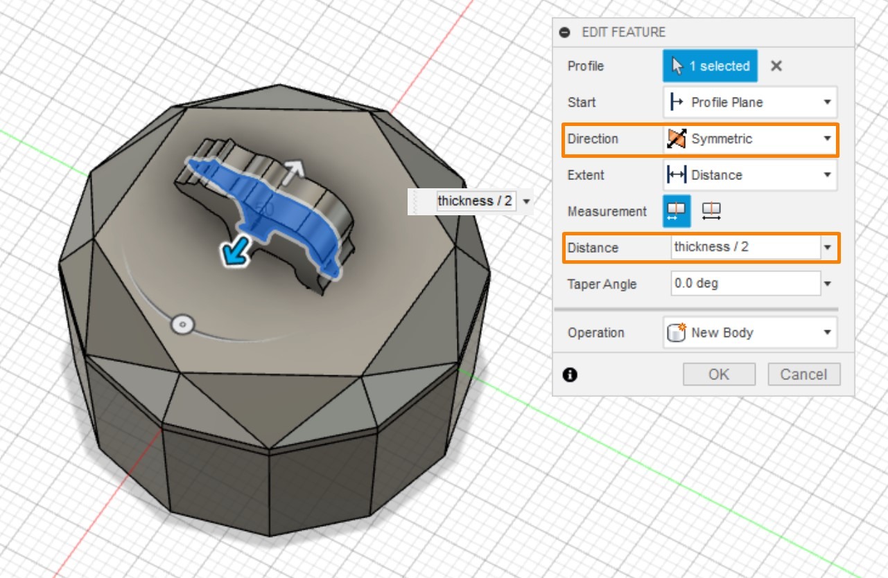
Select the Sketch of bear and Extrude it with the following settings:
-Direction: Symmetric
-Distance : Thickness/2
Symmetric extrusion allows the bear to maintains the same center in this process and hence avoid the modifications. Comparing to the location an thickness, the scale of the bear can be relatively flexible and can be adjusted based on personal preference.
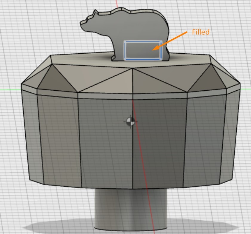
Our instructor Mikko suggested that the legs of the bear may not be milled with the 3.18 milling bits. So the spaces was filled with an extruded rectangle.
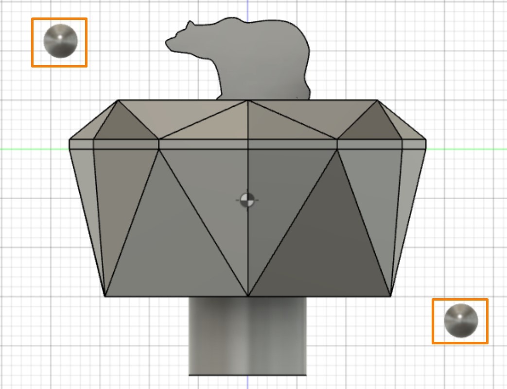
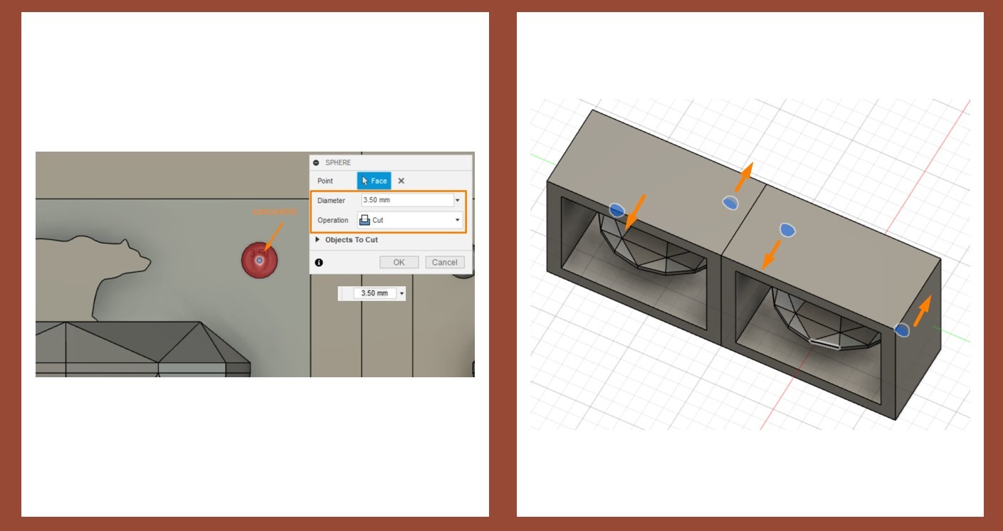
3. Alignment Pins
I created two sphere pins for better alignment.
The pins can be generated by Top Menu >> Create >> Sphere >> Diameter=3.5 mm
When locating the pins, the distance from between the pins and models needs to be taken into considerations. In my case, because I am using a 3.18 mm milling bit, I left 3.5 mm to 4 mm between the sphere and objects.
These pins will be further processed for matching after spliting with boolean functions.
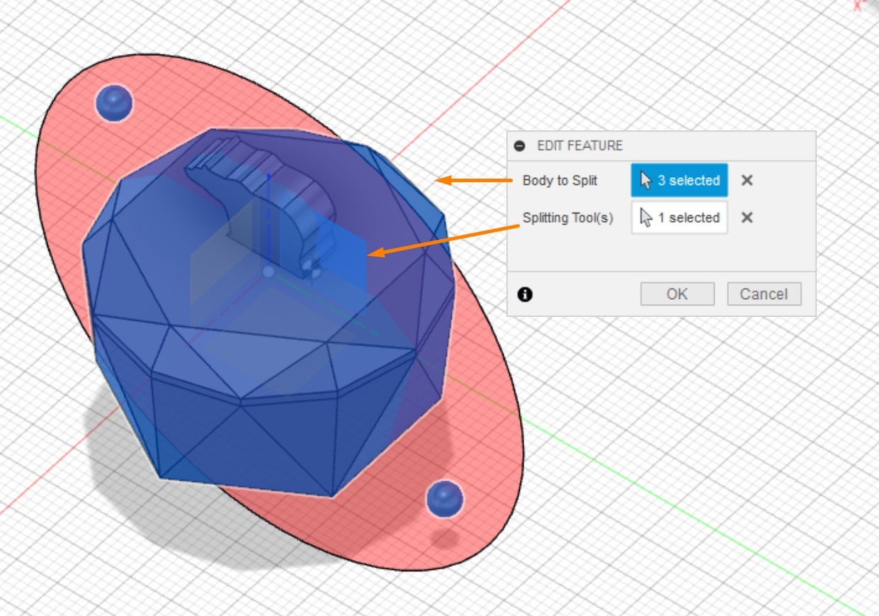
Split the Model
The next step is to split the model and create a shell outside it.
Keep all bodies selected and split them by Top Menu >> Modify >> Split Body
-Body to split: Bear, Diamond, Pins
-Splitting Tool(s): X Plane
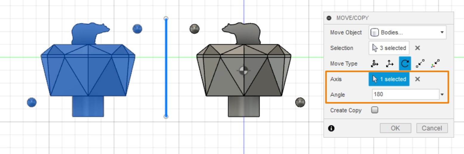
For convenience, turn the bodies on their left or right side and create a Auxiliary line, which will help us easily rotate the models and the shells.
Then, select one side of the splitted bodies and roatet by Modify >> Move/Copy
- Move Type: Rotate
- Axis: [the Auxiliary Line]
- Angle: 180°
On the next, sketch a rectangle around the models, which will serve as the base of the mold's shell. Again, the distances between the edges, models, and pins, which are ideally between 3.5 mm to 4mm, need to be considered in this process.The bottom edge should overlap with the bottom line of the input tunnel.
After this, select the four edges of the rectangle and rotate them again by Modify >> Move/Copy
- Move Type: Rotate
- Axis: [the Auxiliary Line]
- Angle: 180°
- Create Copy: yes
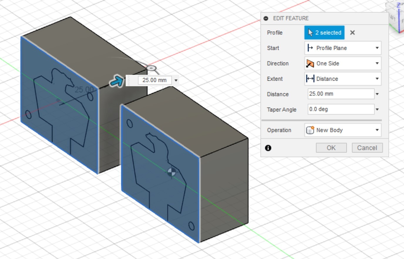
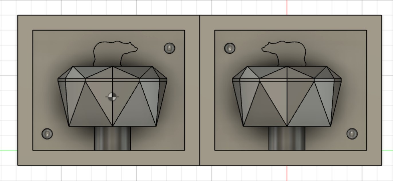
Then, two identical half of the model is ready to be transformed into molds.
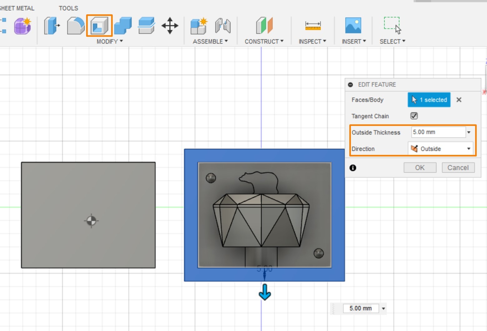
Shell the model
Select both rectangles and Extrude for 25 mm.
Top Menu >> Modify >> Shell
- Outside distance: 5 mm
- Direction: Outside
The last step is to process the alignment pin.
Create >> Sphere >> Select the center of the Pin
- Diameter: 3.5 mm[same as the pin]
- Operation: cut
In this way, the pins can match with each other.
Milling
Generate Milling Path
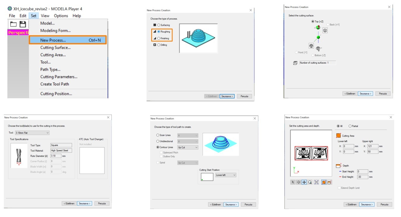
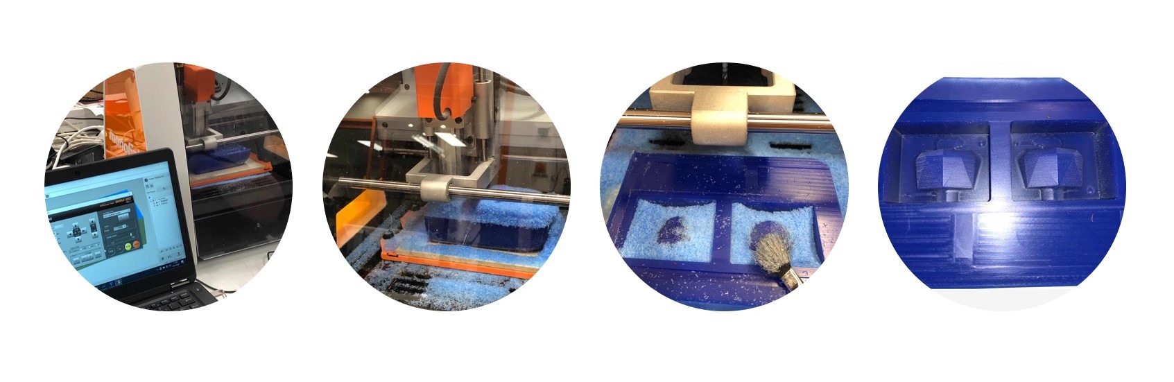
Open MODELA and import the STL file of the mold and adjust the orientation and origin.
Top Menu >> Set >> Model
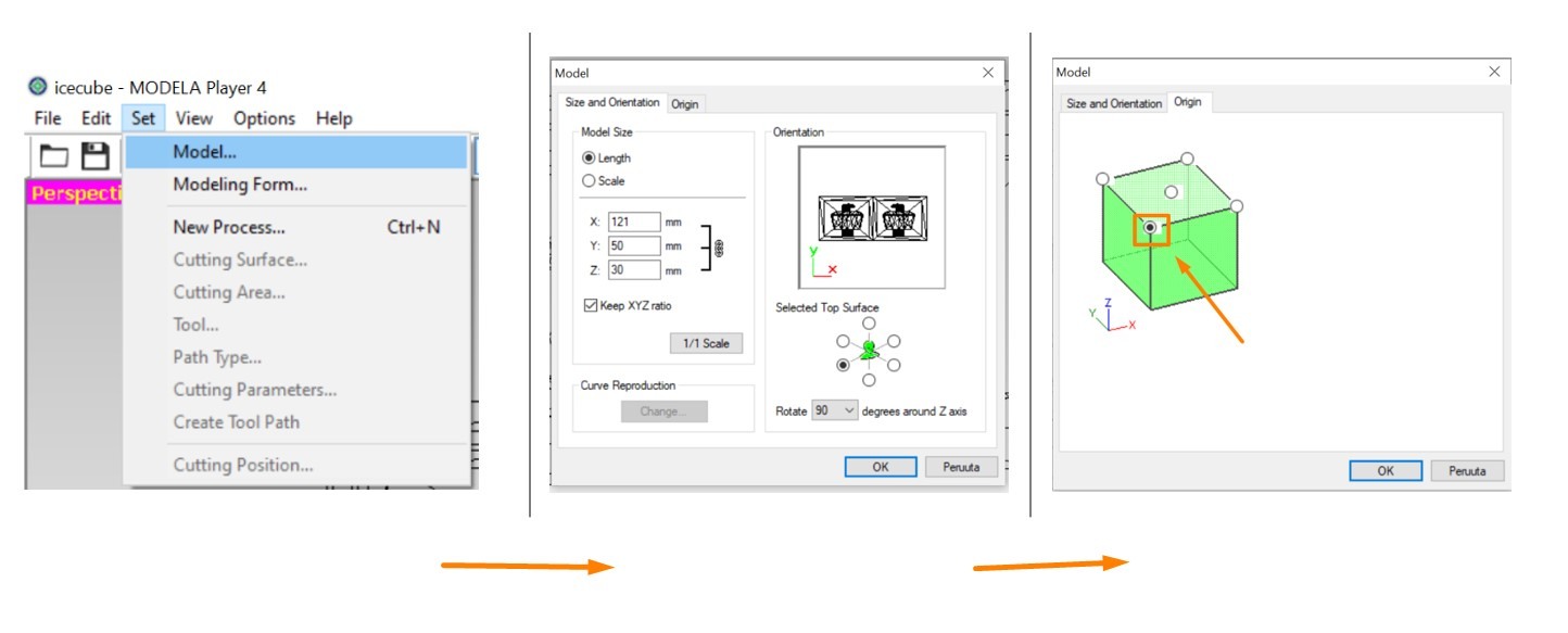
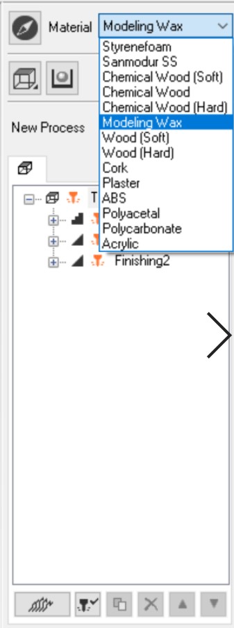
The selected material from the Modela was preset as milling wax. However, this section should be double checked before milling because choosing the wrong material will lead to errors.
After adjusting the model. both Roughing and Finishing paths should be generated.
Set >> New Process >> Roughing/Finishing
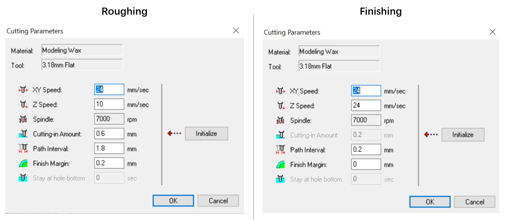
If the mold does not need special adjustment, it is fine to maintain the Default Settings on each step.
Then, select File >> Preview Cutting, and a simulation of the milling process will pop out.
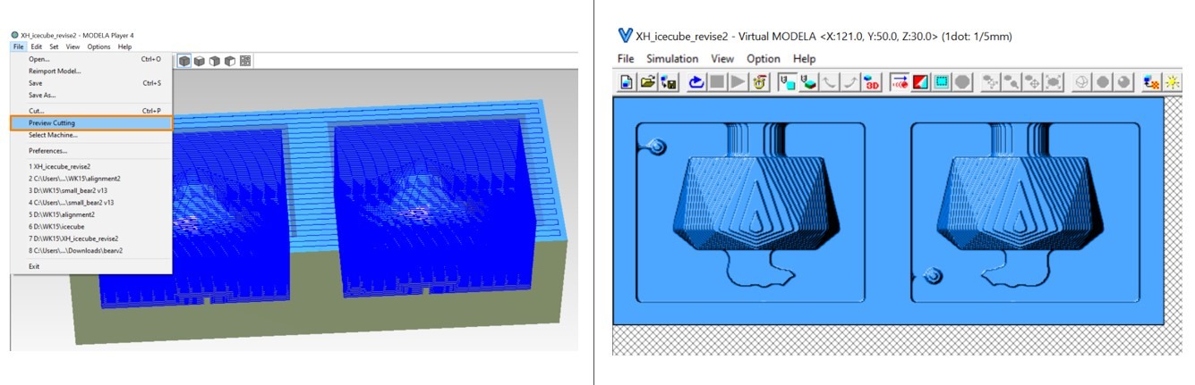
Clicking the milling icon on the right bottom corner will export the files and directlt sent them to the SRM-20 Milling Machine. The adjustment of the milling origins are the same as the previous weeks when milling the PCB boards.
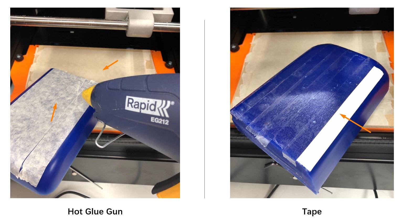
Milling the Wax
The wax blocks can be fixated on the milling platform with either hot glue gun or with double-sided tapes. If using the hot glue gun, both the wax block and the platform should be covered with tapes before applying the hot glue. More detals about manupulatng the SRM-20 machine can be found in Week 4 and Week 6 assignments.
It takes several hours for the entire molds to be milled.
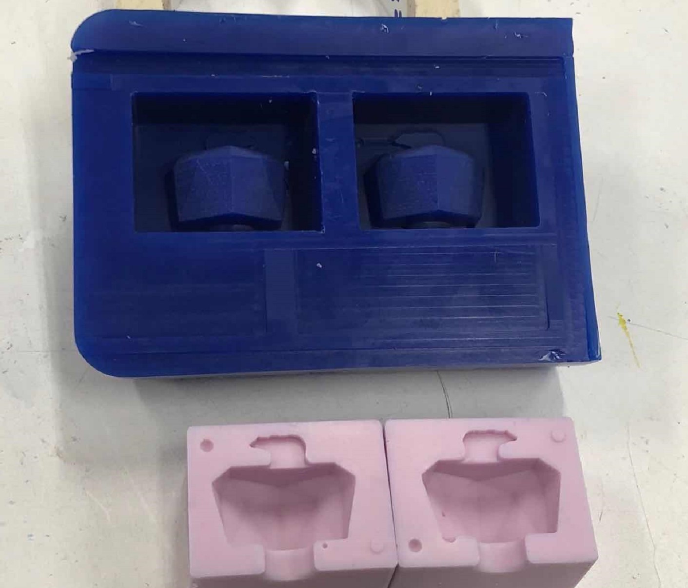
Casting
Mixing the Material
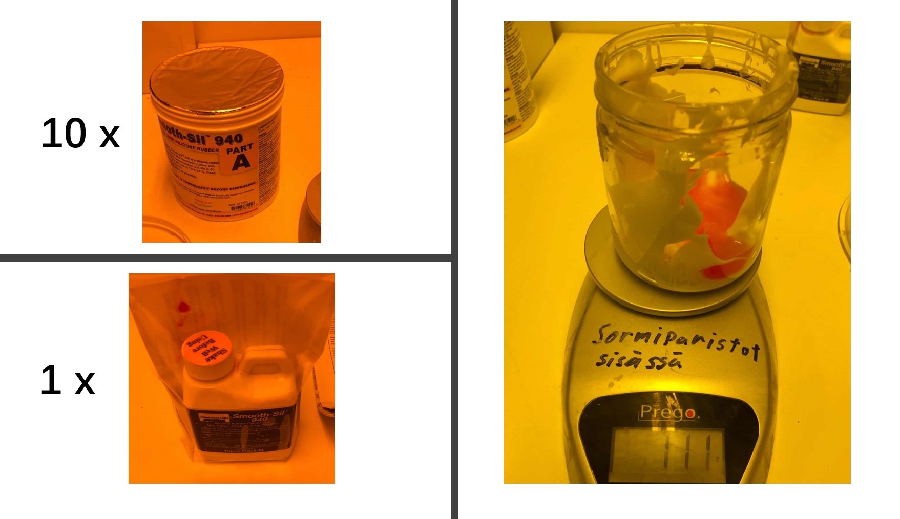
I used Smooth-Sil™ 940 Food safe Silcon to cast the mold.
The process is quite simple: Mix Smooth-Sil Part A and Part B with the ratio of 10 (A):1 (B) and stir the mixture until the two parts become well-merged.
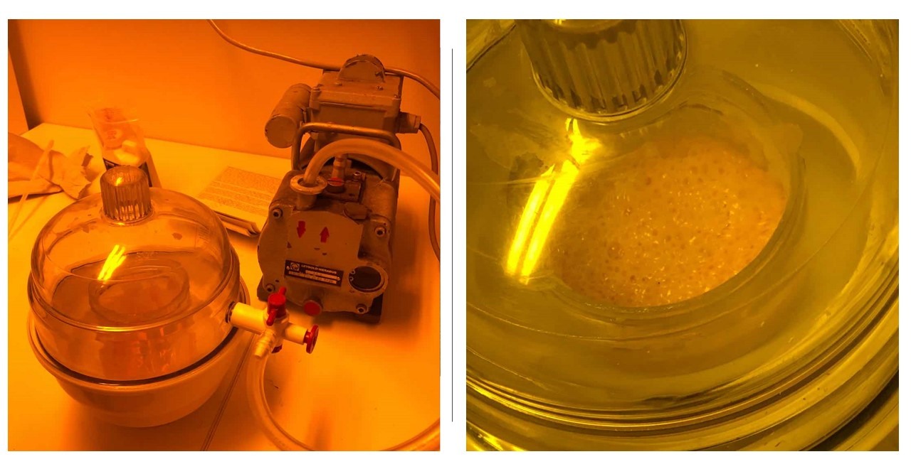
In order to remove the air in the mixture and avoid the bubbles in the final product, the mixture should be put into a vacuum chamber for 3-5 minutes.
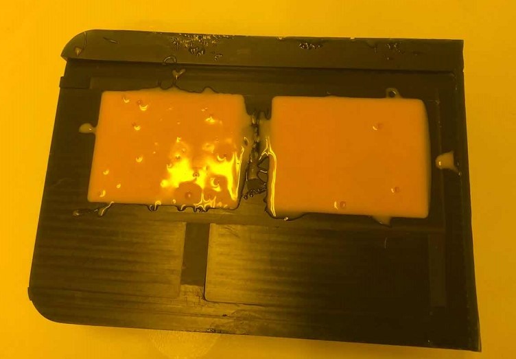
The last step is to pour the mixture into the mold carefully and slowly. If being rush in this step, the final mold may have bubbles on its surface. In my case, because the material overflows during vacuum processing, I do not have adequate time to remove the bubbles in the material and hence having tiny bubbles in the final outcome. Wetting the surface and using sharp tips to break the bubble can help to improve the surface condition as well.
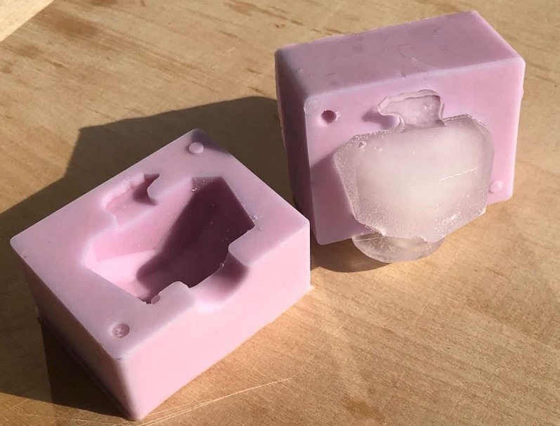
After 24 hours, the mold is ready to be taken out.
When the mold is taken out, the wax block will be melt and reused for future projects.
Group Assignment
The group assignment of this week focus on reviewing the safety data sheets for each of your molding and casting materials and then making and comparing test casts with each of them. Please check our Group Assignment Page for more details.
Files
Fusion FIles:
● Bear_and_Iceberg.stl ● Bear_and_Iceberg.f3d
Milling Files:
● Roughing.prn ● Finishing.prn ● MDT file ● MPJ file