What tasks have been completed?
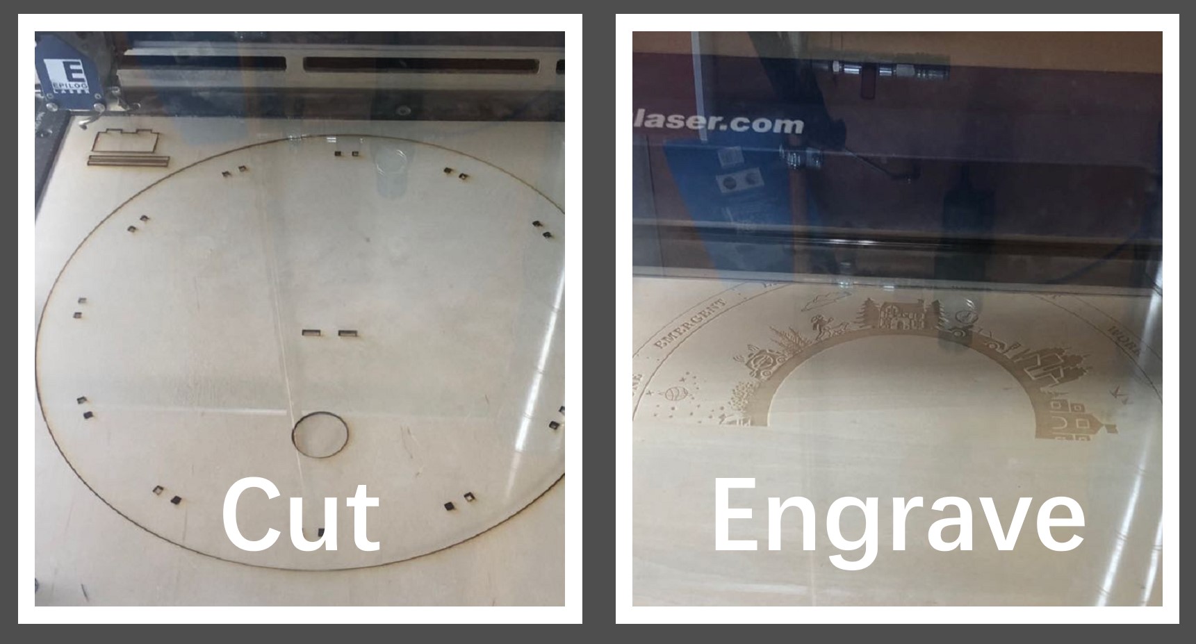
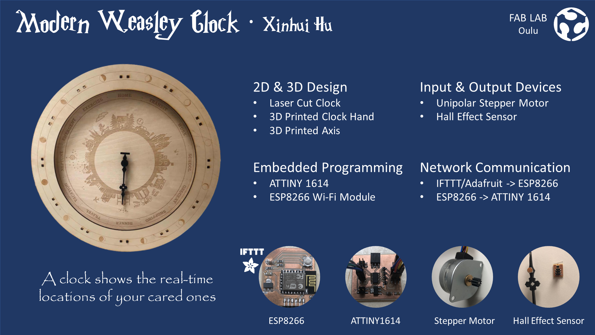
✓ The clock body parts are laser cut and assembled properly
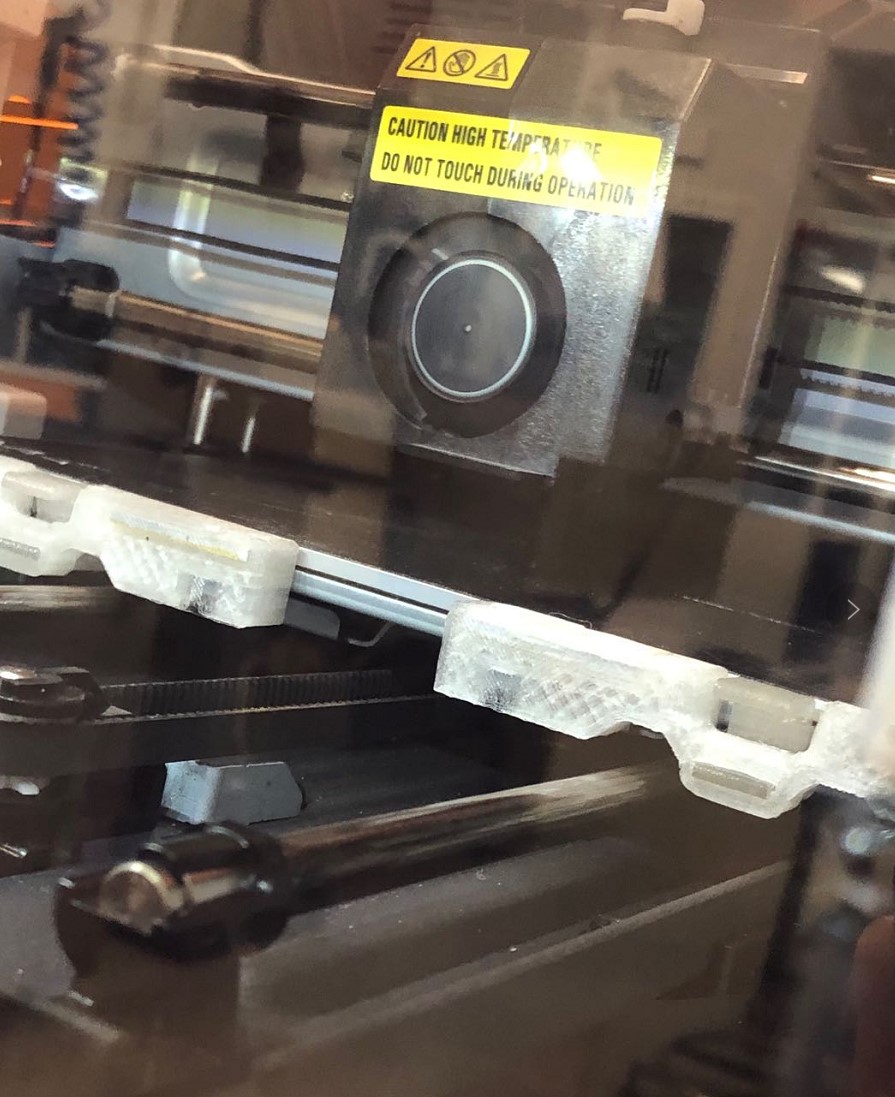
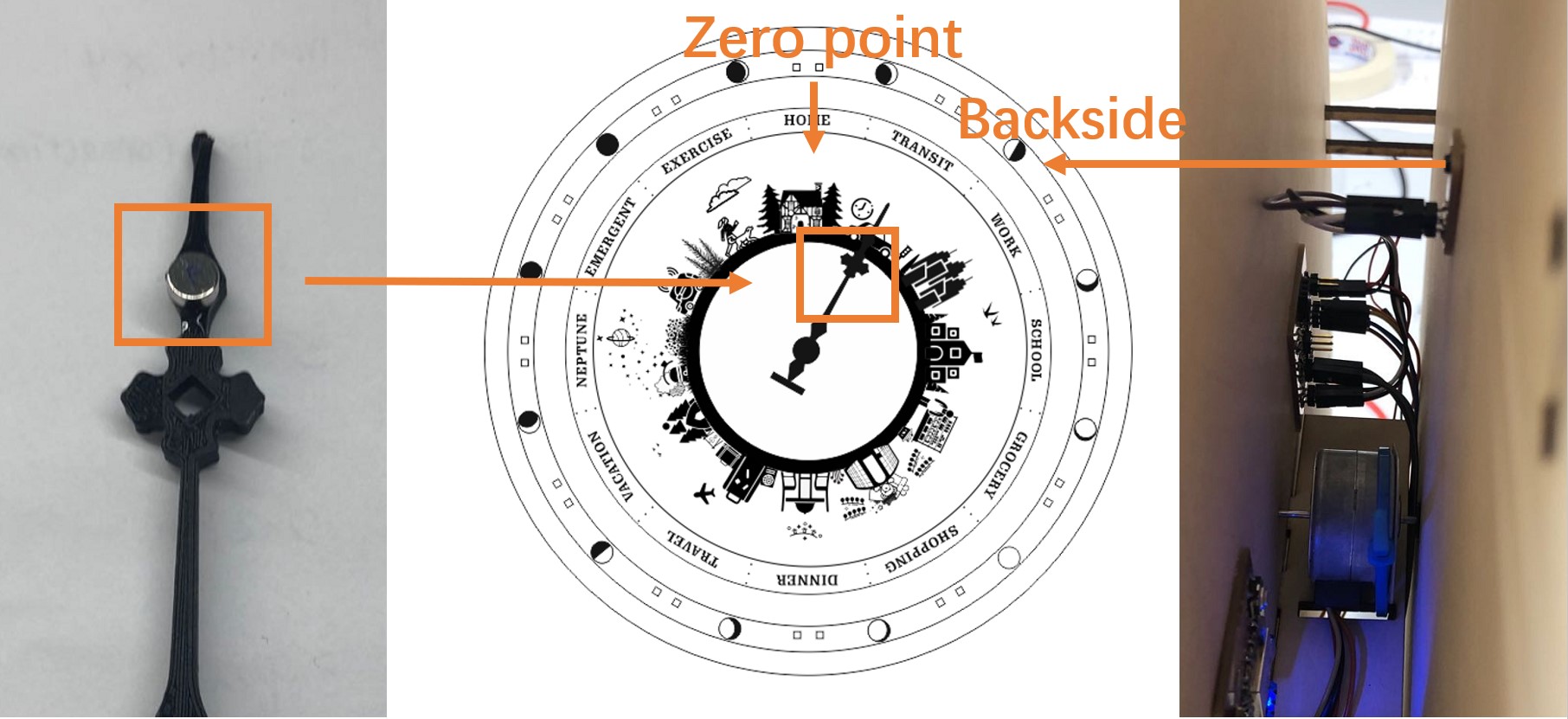
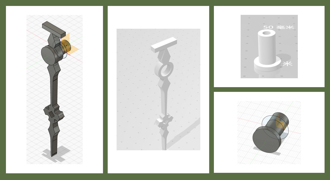
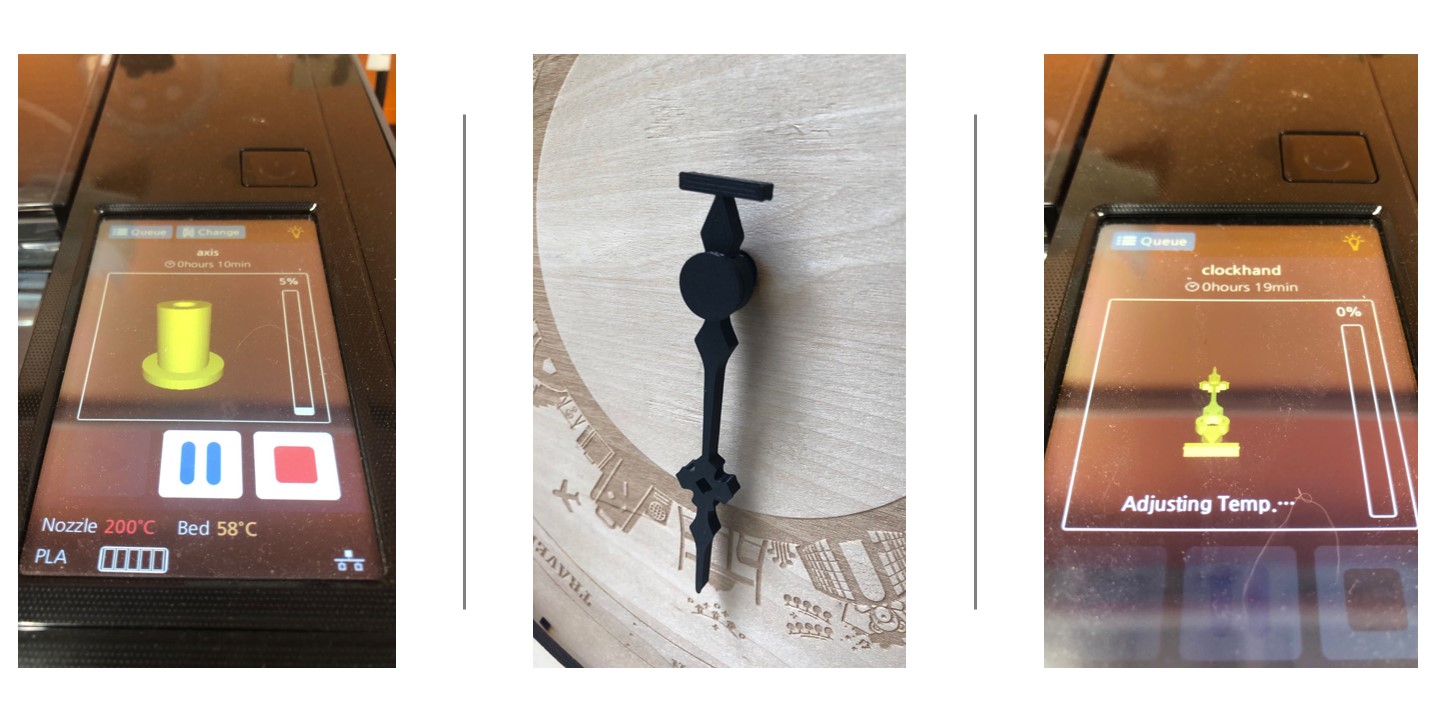
✓ The clock hand and axis are 3D printed and fits the motor gear well
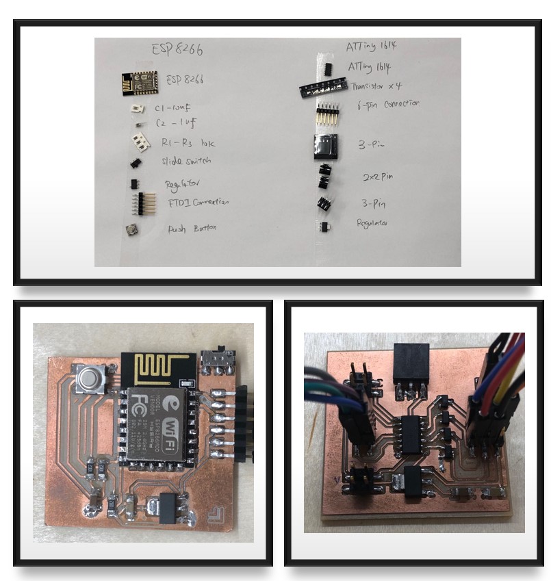
✓ All electronic components are collected
✓ All PCB boards are designed, milled and soldered
✓ All chips are programmed
✓ The communication between different components has functioned smoothly
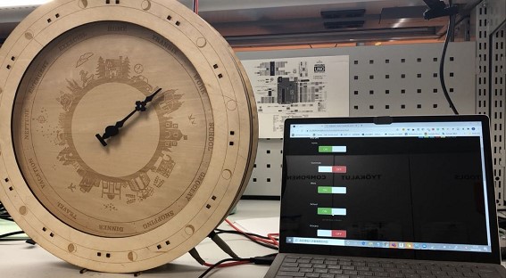
✓ The modern Weasley clock worked as expected
What's working? what's not?
In brief, all major objectives that real-time have been achieved.
● The clock can detect the location change
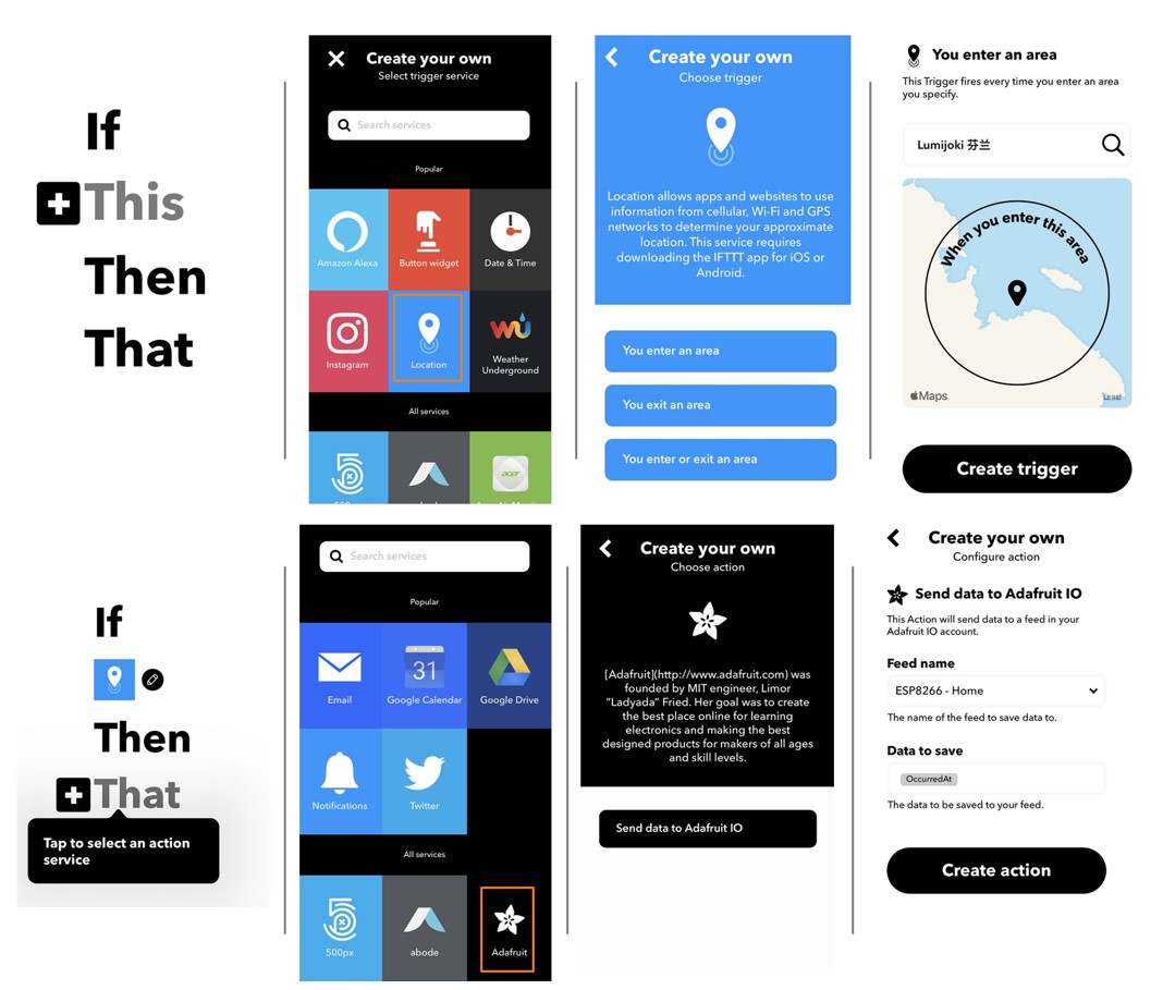
● IFTTT can successfully trigger the location change event and push to Adafruit IO
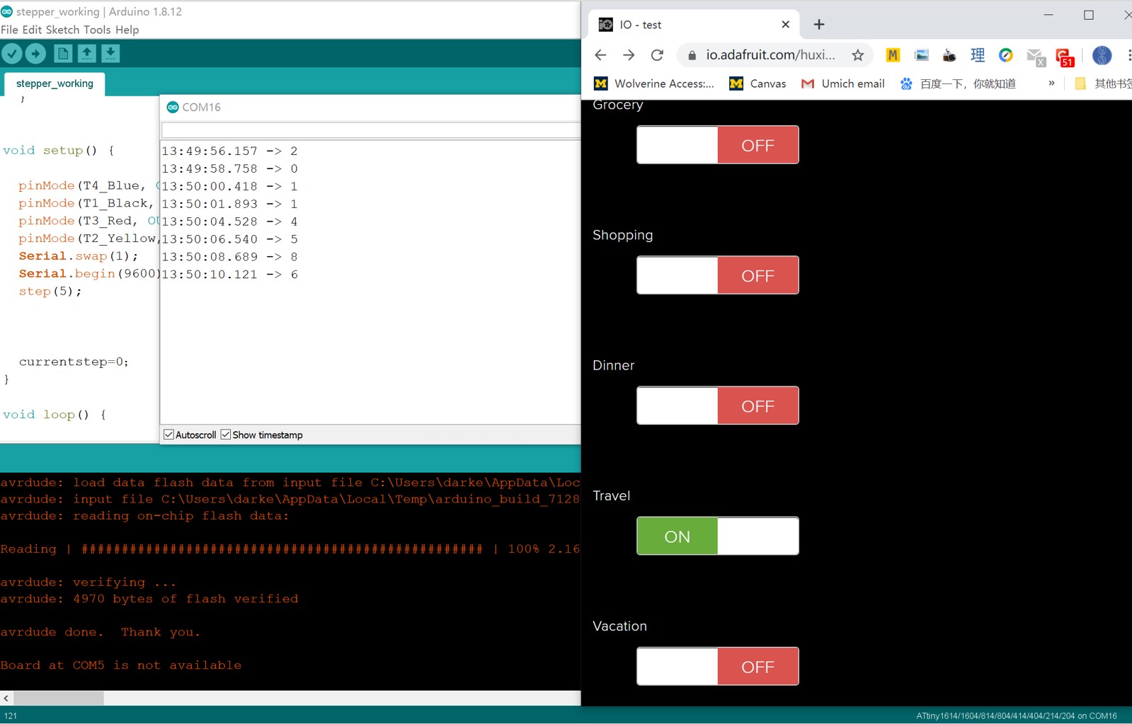
● Adafruit IO can received the trigger and send corresponding location code to ESP8266
● The clock can demonstrate the real-time location change
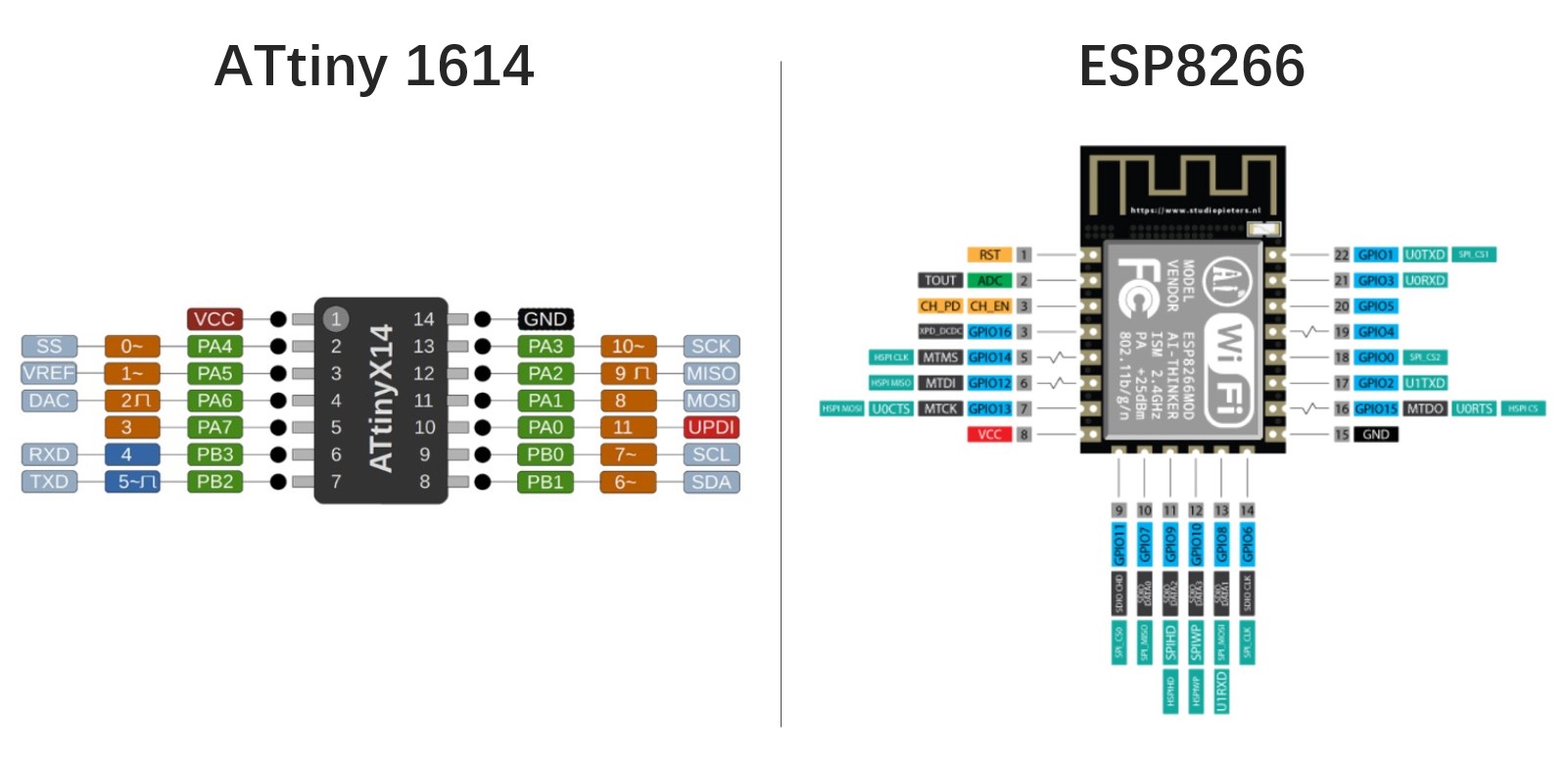
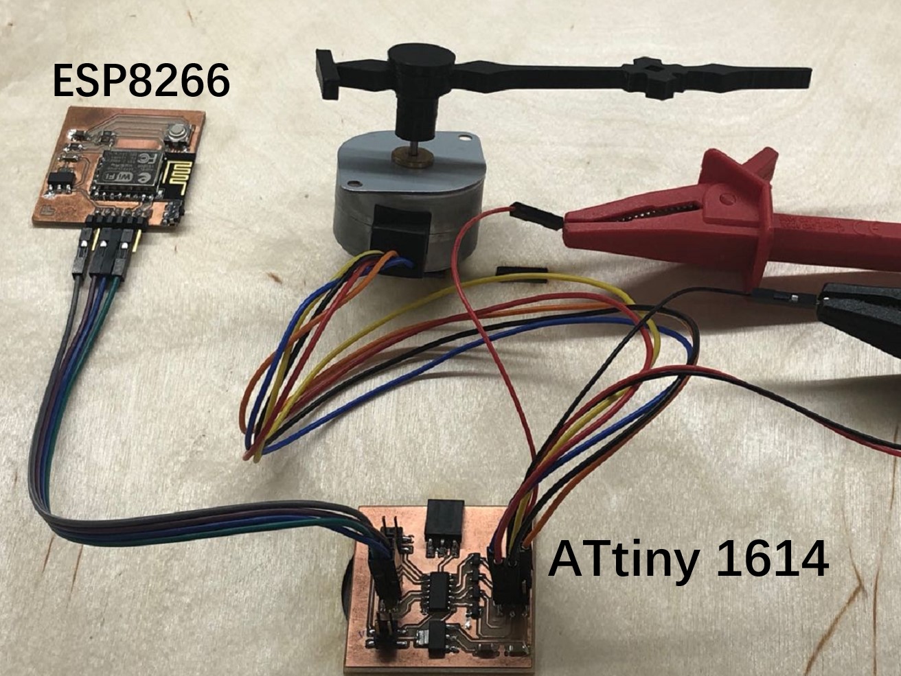
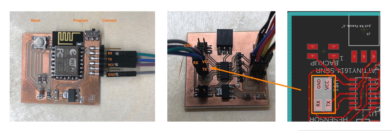
● ESP8266 board can successfully send this signal to the ATtiny 1614 microcontroller
● ATtiny 1614 microcontroller can control the stepper motor to move to the expected positions
● The clock functions properly in general
● The Hall effect sensor can detect the approaching magnetic field and hence set the zero point
● The 3D printed clockhand and axis fit the motor gear well
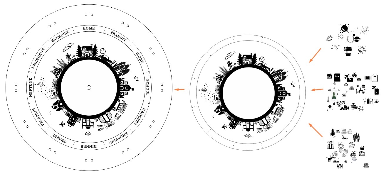
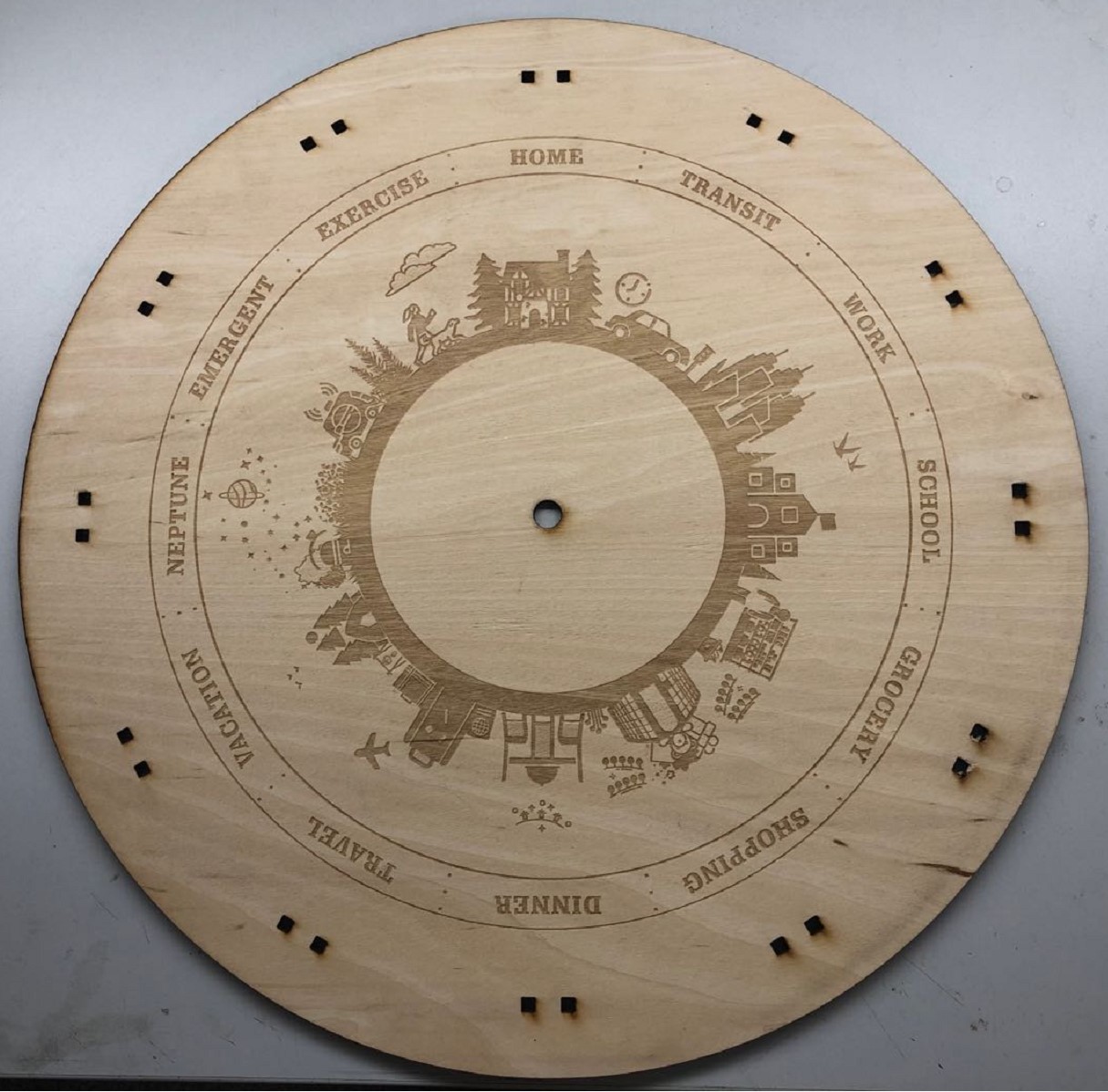
● The laser cut clock body parts properly match with each other and stay stable
● The power sources provide adequate power supply to the device
On the other hand, some of the less essential features, which are nice to have but not necessary, are not yet achieved.
● The clock cannot yet track and demonstrate the locations of multiple users
● The major barrier is to control multiple clockhands with a single motor.
While a possible mechanism has been ideated, the technical details was not fully examined due to the scope of this project.
● The LED that indicate the emergent status was not integrated yet
● An red bulb was considered to be used to indicate the emergent status on the clock. The ATtiny board has reserved pins for this function, while this version of prototype does not include this section.
● The time spent at each location are not calculated yet
● When ideating the project, I was considering to calculate the time spent at each location and push the information to the users for promoting life-work balance. This function is not integrated in this version of prototype.
What questions need to be resolved?
As mentioned above, if I would like to add more values to this project, I need to resolved these questions:
● How can I control multiple clockhand for different users at the same time?
● How can I open a hole for the LED bulb on the clock face without breaking anything else?
● Based on the time spent at each location, how should I give proper suggestions to the users regarding life-work balance
What happens when??
The timeline of the task completion is as below.
The first half of the process has majorly focused on exploration and skill acquisition, while the second half focused on the actual designing, manufacturing, prototyping, and implementing issues.
Week 0
Final Project Ideation
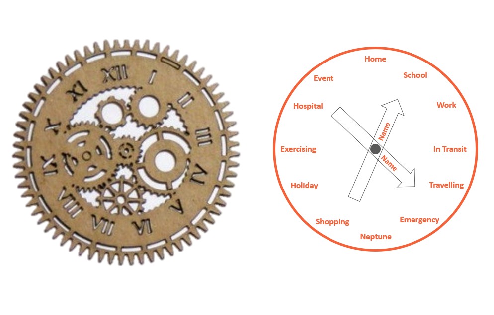
- In this week, I have brainstormed and screened ideas about the potential final project ideation. The idea of creating a modern Weasley Clock, which replicates the real-time location tracking function of the magic clock owns by the Weasley family in Harry Potter, simply jump out of my mind.
By searching the relevant tutorials and designs, I acquired the general knowledge about the mechanism of achieveing this goal and decided the decoration style of this clock.
Week 3
Laser cutting skills acquired
- In this week, I have learned how work with the laser cutting machines in our lab.
The knowledge I acquired in this week has helped me a lot when laser cutting the clock face for my final project.
While I have decided to use laser cutting for my final project, the actual design and manufacturing processes were accomplished much later.
Week 5
3D printing skills acquired
- In this week, I learned how to work with the different 3D printers in our lab.
In my final project, I have made the clock hand and the axis with the Sindoh 3D printer in our lab.
Again, while I have decided to apply 3D printing techniques in my project during this week, the actual design and manufacturing process were accomplished later.
Week 6
PCB Design Skills acquired
- In this week, I have learned basic PCB board design knowledge with Autodesk Eagle, which provides essential support to me in designing the circuits for my final project.
Week 8
Embedded Programming
Knowledge acquired
- In this week, I have learned how to interpret the datasheet of different chips, especially the functions of each pin.
I have specifically examined the datasheet of ATtiny 1614 and ESP8266 Wi-Fi module 12-f and learned how to use them in my final project.
Week 9
Input Devices Set up
Hall Effect Sensor
- In this week, I have learned (1) how to use sensors to collect information from the environment and (2) how to use the Hall effect sensor and magnet to set the zero point for the motor that I used in the output week and for the final project.
Week 10
Applications & Implications
- In this week, I began to nail down the design details by answering the questions regarding techniques and materials that will be used for the final project.
I also sketch the first version of the clock face design and dive into the first round iteration in this week.
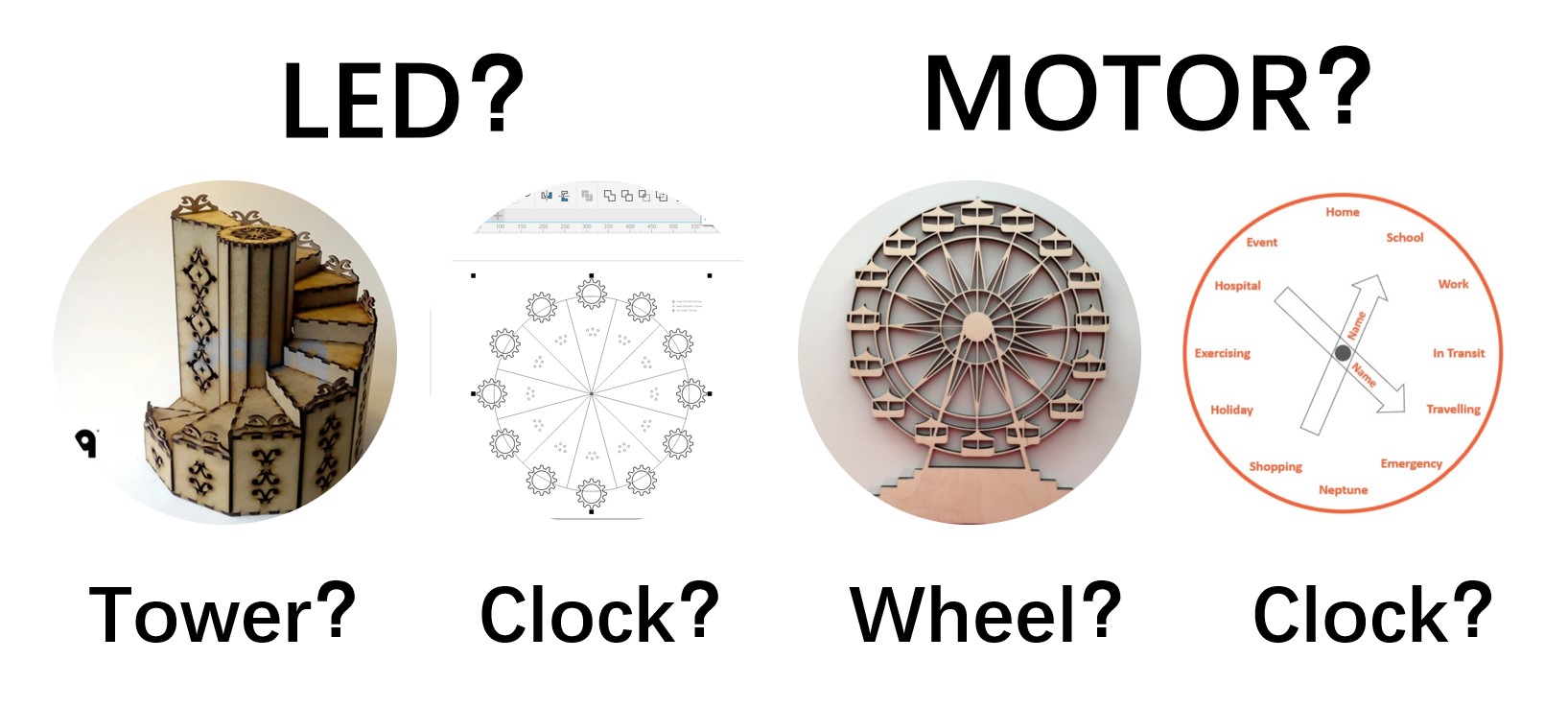
Previous projects on creating one's own Weasley clocks either use motors to control the clock hand or use LEDs on different area to present the location change.
At this stage, I have considered both possibilities and made corresponding plans. For example. I have created four potential designs that use either LEDs or motors, which respectively take the form of motor-based clock, motor-based ferris wheer, led-based clock, and led-based tower.
The decision of using motor and retained the form of clock is made in a later week.
 tower credit / wheel credit
Week 11
Output Devices Set up
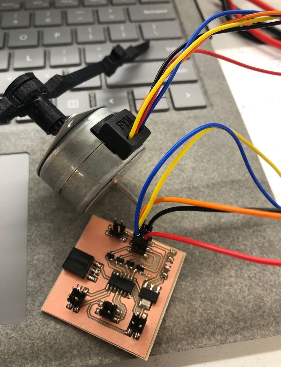
Stepper Motor
- In this week, I have learned (1) how to output information by LCD screen and (2) how to control a Jameco Unipolar Stepper Motor as the output device that indicate the real-time location changes.
After evaluating the feasibility of different plans, I evetually decided to adopt the motor-based clock plan. Due to the availability, I choosed to use the unipolar stepper motor that I gained from our lab.
I used a ATtiny 1614 chip to control the motor. However, the mismatch of the motor datasheet and the actual coil-lead mapping has induced huge problem, which was not solved until later in this process.
Week 14
Network & Communication
Mechanism Figured Out
- In this week, I have learned how to communicate two devices by network and serial communication. In my project, I have used ESP8266 to receive location change push from the mobile devices and send the received signal to the ATtiny 1614 microcontroller via serial commnication.
June 01- 14
Prototyping
- In these weeks, I have finalized the 2D and 3D design of the clock parts and manufactured them.
2D design: laser cutting
3D design: 3D printing
June 15 - 22
Electronic & Mechanics
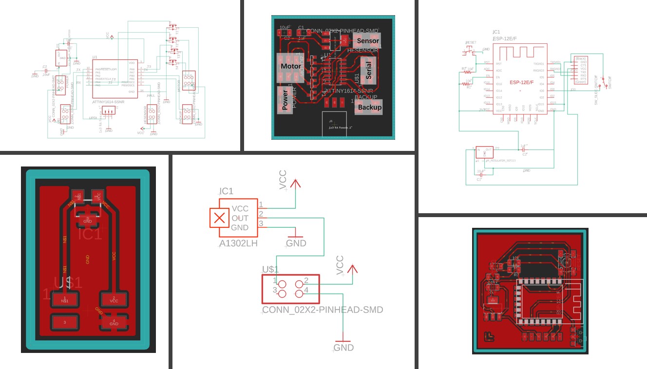
Electronic Design
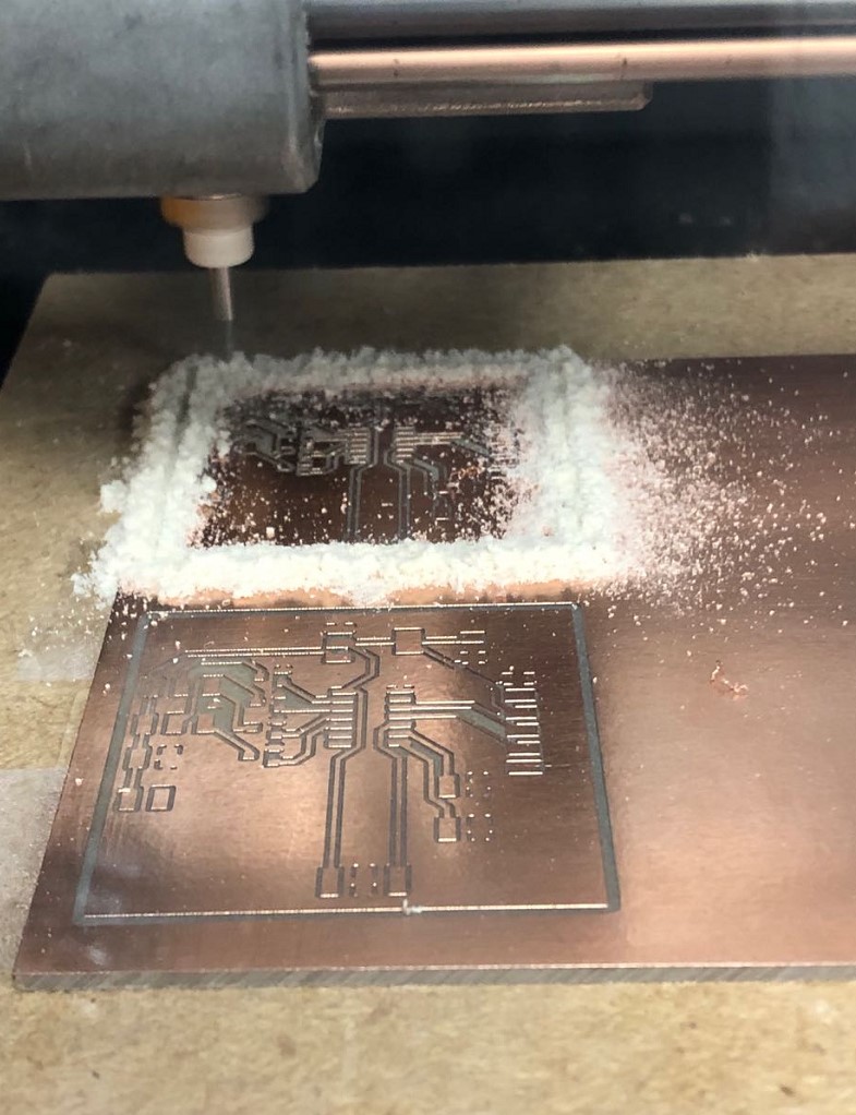
- In this week, I have finalized the electronic design, milling, and soldering works.
Electronic Design
PCB Milling
Soldering
June 23-30
Communication & Debug
- In this week, I have finalized the networking and communication, as well as the troubleshooting and debugging works.
Networking
- Location Change Trigger
Based on IFTTT and Adafruit IO
Adafruit to ESP8266
Test & Debug
July 1
Final Project
Presentation Accomplished
Presentation Slide
>Presentation Video
What have I learned?
I have acquired these skills and gained experiences with these devices and software:
-2D Design
Software: CorelDraw, Inkscape
-3D Design
Software:Fusion 360, Blender
-Laser Cutting
Devices: Epilog Laser Fusion laser cutter
-3D Printing
Devices:Stratasys Fortus 380mc, Sindoh
Software:GrabCAD Print + Control Center
-PCB design
Software: EAGLE, MIT mods
-PCB Milling
Devices:SRM-20
Software:Vpanel for SRM-20
-PCB Soldering
Devices: Solder iron, tin remover
-Embedded Programming
Devices: oscilloscope, multimeters
Chips:FT232, ATtiny 1614, ESP8266
Software: Arduino IDE,
-Communication
Software: IF This Then That, Adafruit IO, Arduino IDE
-Input Device
Devices: Hall Effect Sensor
-Output Device
Devices: Servo Motor, Unipolar Stepper Motor
-Debugging
Devices: oscilloscope, multimeters
Software: Arduino IDE
Besides the technical skills, I have also acquired knowledges in project management, IP and license management, and developed group cooperation skills in this progress.
As a conclusion, I have acquired intensive knowledge in the fields of (1)Subtractive Fabrication, (2)Additive Fabrication, (3)Embedded Programming, (4) Communication, (5)Input Device, and (6) Output devices, while I have also learned more about IP protection and projectg management. This has been a wonderful journey in product development, which I enjoyed from the very beginning to the end.