Individual Assignment
This week's assignment focuses on (1) adding an output device on a microcontroller board and (2) program it to do something. In this week, I choose to use the LCD screen as the output device and to display texts on the screen. With this board, I managed to show text and time since last resets on the LCD screen.
Board Connection
I connected my Aruduino Uno board and a 16-pin LCD screen via the Bread Board following this tutorial.
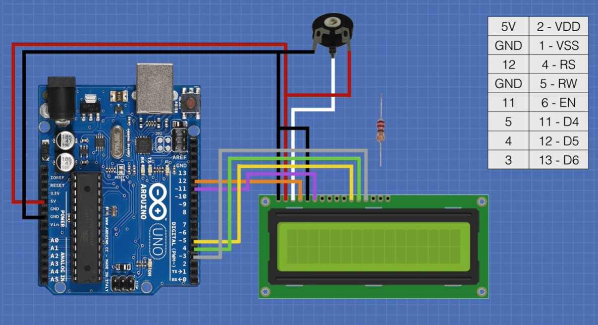
Following this instruction, I connected the board with a little adjustment regarding the connected pin.
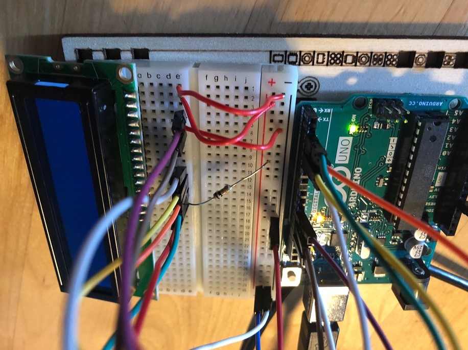
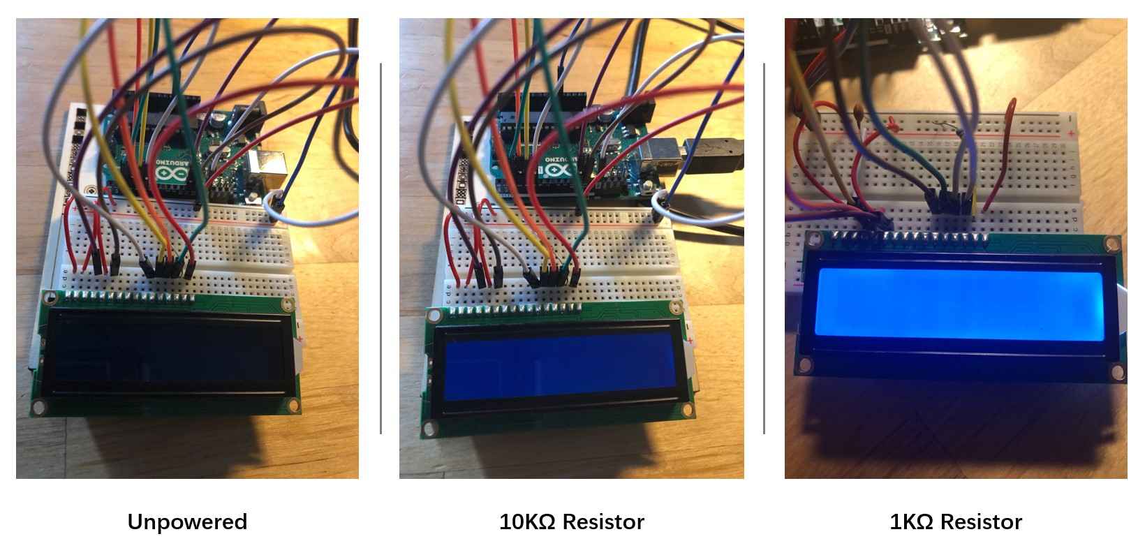
After connecting to the board to the computer, the LCD screen lighted up. However, it is quite dim.
Searching the previous discussions on Arduino forum, I was able to debug the dim light issue. In another tutorial, I learnt that the if I am using my computer to power the Uno board, the actual volt may be less than 5 V. So I substitue the 10KΩ resistor with a 1KΩ resistor, which solved the problem. The screen now looks bright, even without a potentiometer.
However, when I tried to upload the program to the board for first time, even the code was successfully uploaded, the screen remains blank. I was wondering if that was because I did not have a potentiometer.
With the help of our instructor Antti, I figured out the problem. Since I do not have a potentiometer, I should use a capacitor instead, otherwise the V0 (contrast pin) of the LCD screen was not connected.
According to this discussion that Antti sent, contrast pin to the arduinos pwm pin (Pin9 or Pin 3) and filter the oscillation by connecting a capacitor between the lcds contrast pin (V0) and ground or power depending on my lcd.
This solution works. I connected a 101 Capacitor to between V0 and ground and wired V0 with Pin 9 (PWM) on Arduino board.
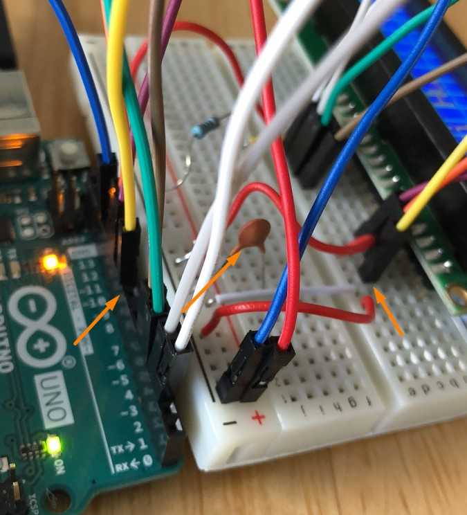
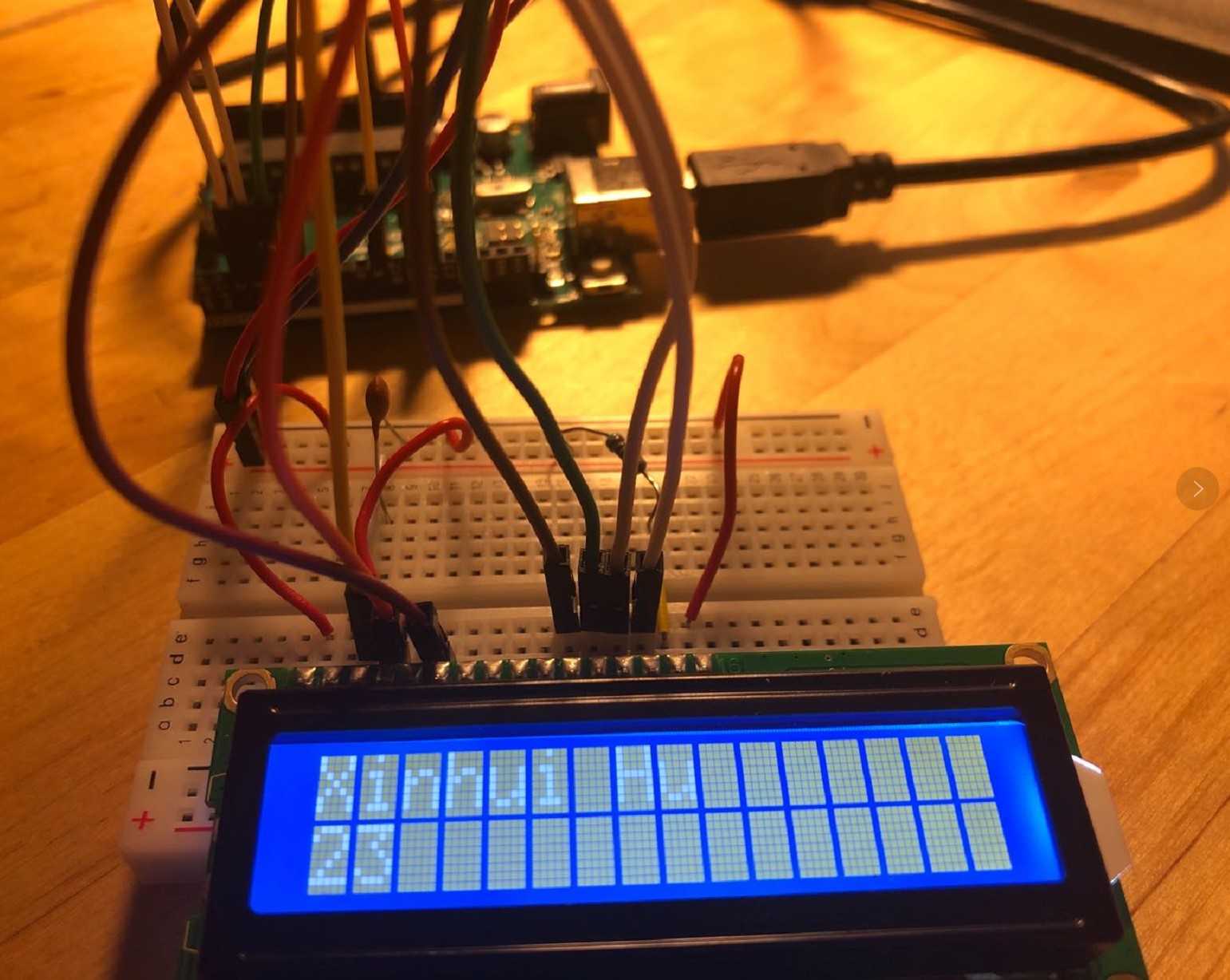
Now the board can show text on the screen.
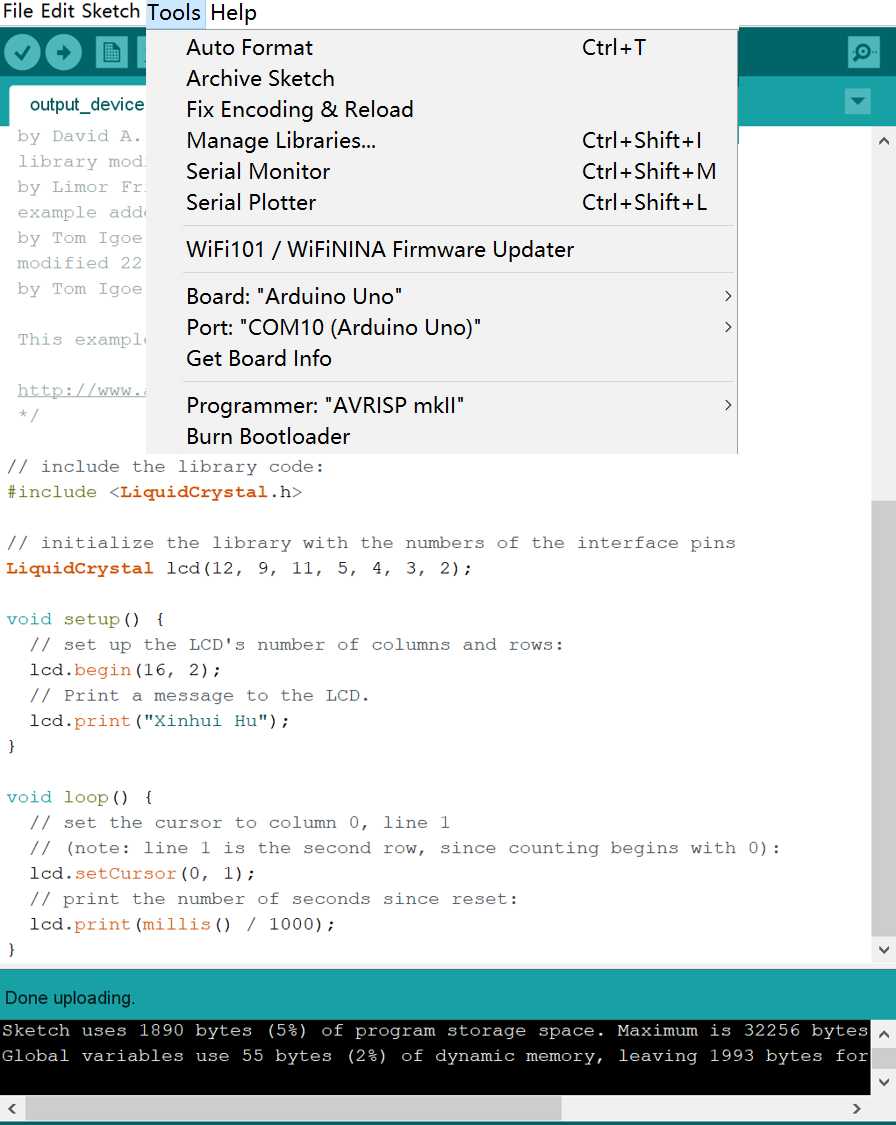
The next step is to uploading the corresponding codes from the Arduino Interface. I used the code provided by Arduino Hello World Tutorial with tiny adjustments.
Because the V0 Constrast Pin issue, I need to include the corresponding PWM pin, which is 9 in my case, to the interface pins.The adjusted codes are as follow. The first function of this code is to show my name on the LCD screen and the second function is to count and show the number of seconds since last reset.
            // include the library code:

            #include <LiquidCrystal.h>


            // initialize the library with the numbers of the interface pins

            LiquidCrystal lcd(12, 9, 11, 5, 4, 3, 2);


            void setup() {

              // set up the LCD's number of columns and rows:

              lcd.begin(16, 2);

              // Print a message to the LCD.

              lcd.print("Xinhui Hu");

            }


            void loop() {

              // set the cursor to column 0, line 1

              // (note: line 1 is the second row, since counting begins with 0):

              lcd.setCursor(0, 1);

              // print the number of seconds since reset:

              lcd.print(millis() / 1000);

            }
After connecting the board with power supplies, the LCD started to work.
Output Devices in Final Project
I used a JAMECO Unipolar Stepper Motor as the output device in my final project, which is controlled by an ATtiny 1614 microcontroller.
By activating the magnets in the correct order via corresponding coils, the motor can turn clockwise or counterclockwise by any designated steps. Thus, in my case, controlling the motor with ATtiny 1614 requires the following procedures.
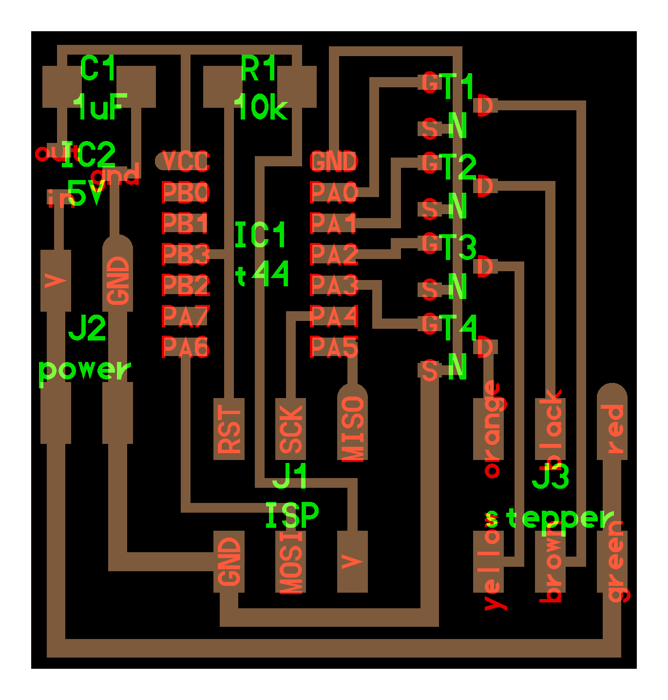
The design of my ATtiny 1614 board derived from Neil's design of ATtiny44 board that used to control unipolar stepper motor. Besides the 4 pins that connected to the transitors that controls the stepper motor, based on the suggestions of our instructors Ivan and Antti, I have used 3 additional pins for hall effect sensor and other potential usage.
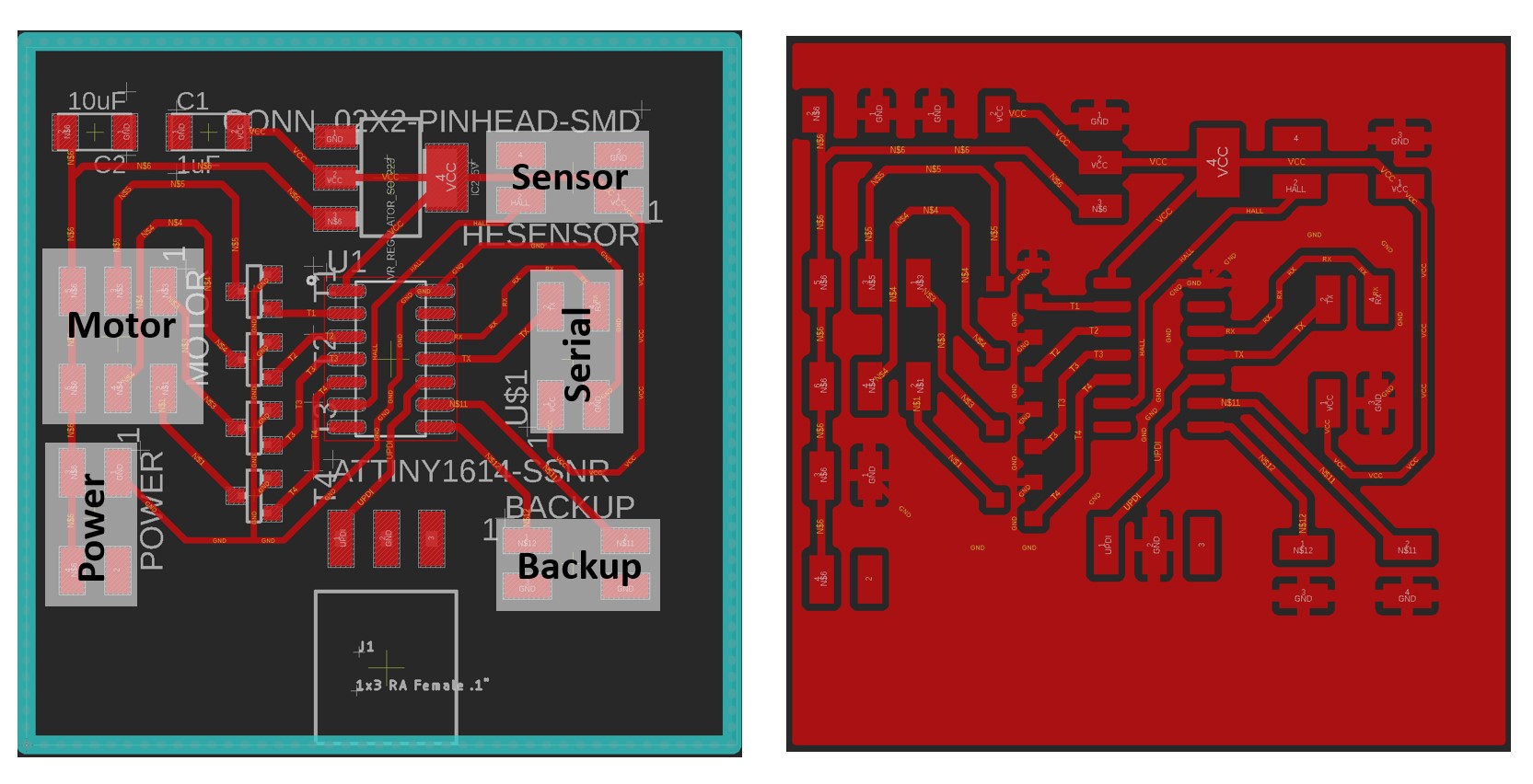
The schematics and board designs are as follow:
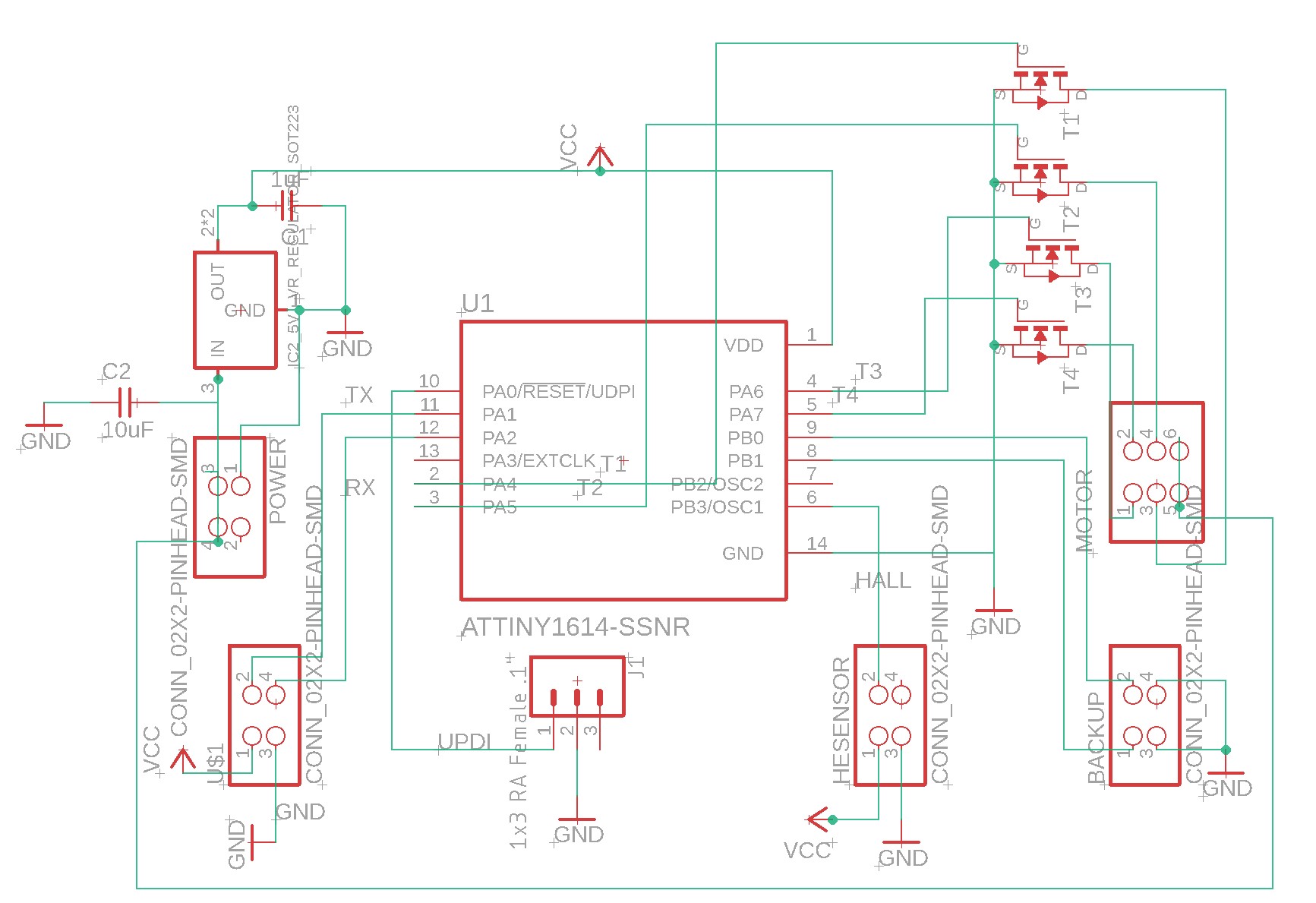
There is one thing noteworthy when wiring the components: the GND line underneath the 4 transitors should be set to 13~14 mil instead of the commonly used 16 mil. Otherwise, the line will too broad for the transistors and hence cannot be drawn. More details of manufacturing the board with SRM-20 machine can be found in Week 4 and Week 6, while more information about the board design can be found in Week 8
In order to make the motor functional, figuring out the mapping between leads and coils has been an essential step. However, in my case, the leads of the motor are not ready for direct use, connectors needs to be installed on the leads. So my work with the motor started with preparing the leads.
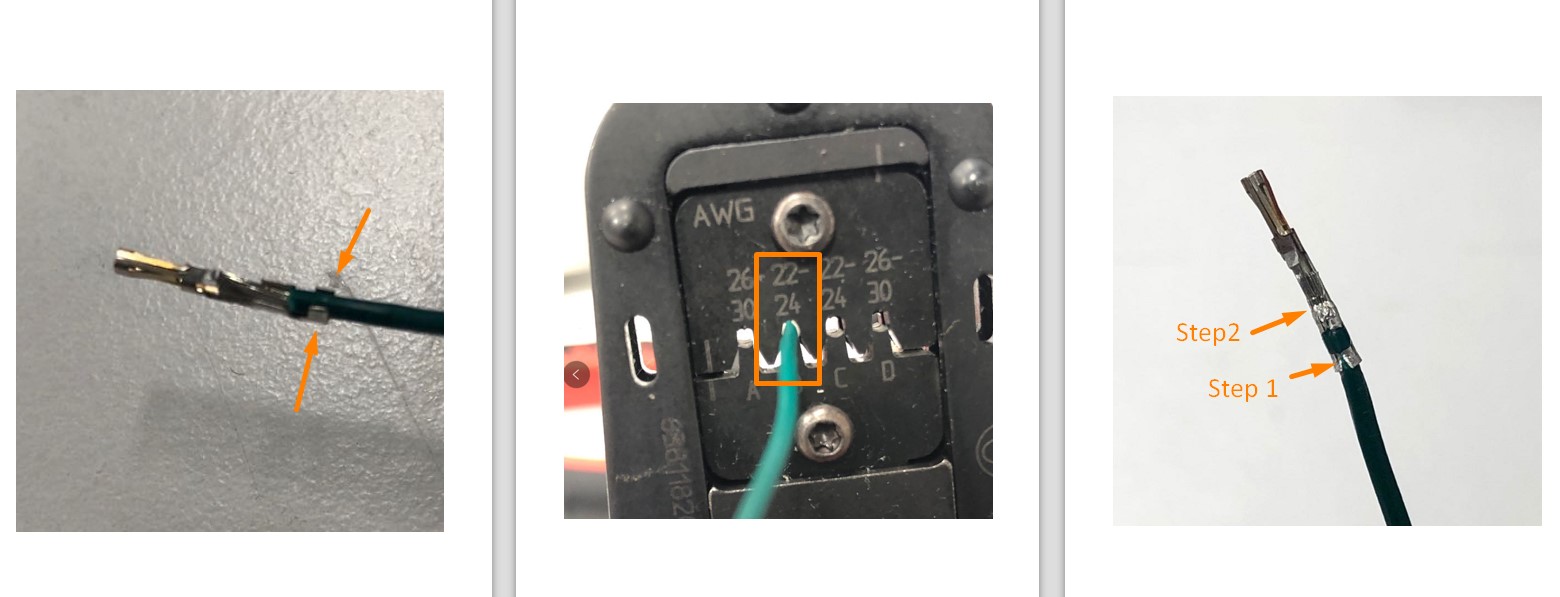
0. Prepare the Leads
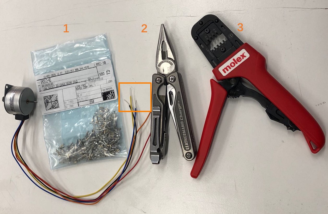
First, take a piece of the metal from bag 1 and use the sharp clipper (tool 2) to fix the metal onto the lead. Then, carefully put the metal-covered lead into the appropriate slots of tool 3 and squeeze.
In this way, the lead can be installed with connectors.
1. Determine the Coil-Lead mapping
The Jameco Motor I used have 5 leads: Black, Blue, Orange, Red, Yellow.
According to the datasheet, the blue and red leads are on the same coil, while black and yellow leads are on the other coil. Orange lead is the power line.
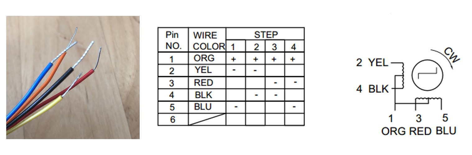
2. Determine the sequence of activation
The activation sequence of this motor to move in clockwise direction has been Yellow/Red-Red/Black-Black/Blue-Blue/Yellow, which is hinted by the Pin No. column is the figure above.
* The hint may not be quite obvious at first, because it does not quite align with the "step" columns. Using the oscilloscope to test the voltage of each lead is a great idea when the datasheet is confusing
Because the 4 leads are controlled by 4 ATtiny 1614 pins via 4 transitors, the activation sequence can be translated into pin status as below:
            STEP 1: Yellow-HIGH; Red-HIGH; Black-LOW; Blue-LOW;

            STEP 2: Yellow-LOW; Red-HIGH; Black-HIGH; Blue-LOW;

            STEP 3: Yellow-LOW; Red-LOW; Black-HIGH; Blue-HIGH;

            STEP 4: Yellow-HIGH; Red-LOW; Black-LOW; Blue-HIGH;
3. Determine the Lead-Pin mapping
At this step, how the motor leads map to the microcontroller pins should be determined.
I did not find a great way to determine the lead-pin mapping other than simply try all combinations, especially when the sequence of activation is not clear.
*If the lead-pin mapping and activation sequence happen to mismatch the same way, the motor can still rotate clockwise as normal, but the mismatch will impose huge challenge in the following steps.
In my case, based on the activation sequence above, the Lead-Pin mappings are:
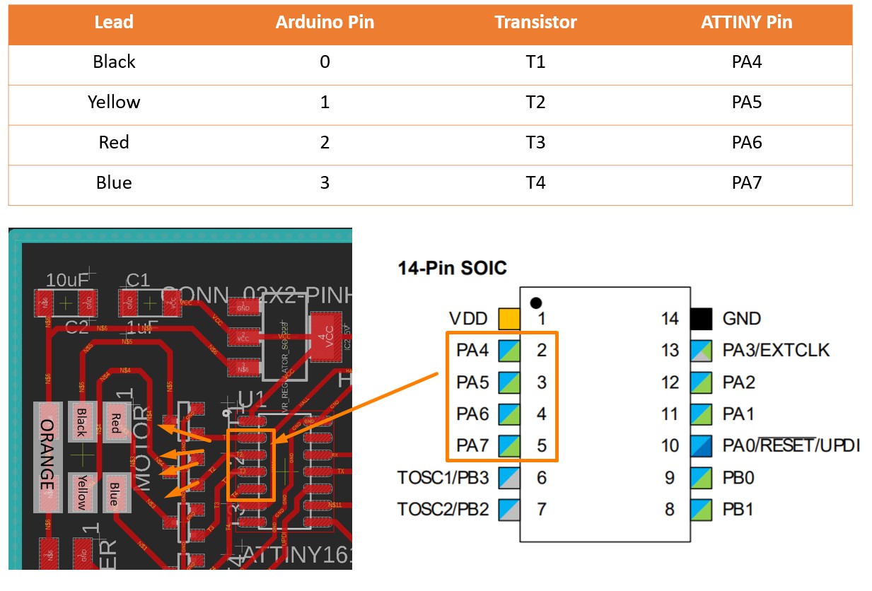
When programming in Arduino IDE, the Arduino Pin number should be used when define the pins.
const int T1_Black = 0;
Activing the leads in this sequence, the motor can rotate in clockwise direction.
const int T2_Yellow = 1;
const int T3_Red = 2;
const int T4_Blue = 3;
4. Programming
The logic of the motor control code are derived from this tutorial.In brief, this code allows the stepper motor to move between designate positions by counting steps.
This code contains three major sections:
-stepMotor(int step) function that defines the activation sequence of the motor coils
-step(int steps_to_move) function that defines the algorithm of the motor to move between positions.
A maximum step, which is the number of steps for a full revolution, is used as the reference to control the moving direction of the motor.
-moveToLocation(int location) function that gets the serial print from the serial input and determines the steps to go
              Motor Control Code


                const int T4_Blue = 3;
                const int T1_Black = 0;
                const int T3_Red = 2;
                const int T2_Yellow = 1;
                const int maxnumberofsteps = 48;

                int currentstep = 0; // Indicates in which step I am (0,47)-> your motor do 48 steps in one rotation
                int current_location = 0; // Indicates in which position I am (0 to 11)
                int num_of_steps = 0;
                String inString = "";

                #define step_delay 500

                void stepMotor(int step_t) {
                   switch (step_t) //
                  {
                    case 0:
                    //Serial.println("Yellow/Red HIGH");
                       digitalWrite(T4_Blue, LOW);
                       digitalWrite(T1_Black, LOW);
                       digitalWrite(T3_Red, HIGH);
                       digitalWrite(T2_Yellow, HIGH);

                    break;

                    case 1:
                       digitalWrite(T1_Black, HIGH);
                       digitalWrite(T3_Red, HIGH);
                       digitalWrite(T2_Yellow, LOW);
                       digitalWrite(T4_Blue, LOW);

                    break;

                    case 2:
                       digitalWrite(T4_Blue, HIGH);
                       digitalWrite(T1_Black, HIGH);
                       digitalWrite(T3_Red, LOW);
                       digitalWrite(T2_Yellow, LOW);
                    break;

                    case 3:
                       digitalWrite(T4_Blue, HIGH);
                       digitalWrite(T1_Black, LOW);
                       digitalWrite(T3_Red, LOW);
                       digitalWrite(T2_Yellow, HIGH);
                    break;

                  }
                 // Serial.print("step_t ");
                  //Serial.print(step_t);
                 }

                // Move x steps (negative will move backwards)
                void step(int steps_to_move)
                {
                  int steps_left = abs(steps_to_move);  // how many steps to take

                  int direction = 0;

                  // determine direction based on whether steps_to_mode is + or -:

                  if (steps_to_move > 0) {
                    direction = 1;
                  }

                  if (steps_to_move < 0) {
                    direction  = 0;
                  }

                  // decrement the number of steps, moving one step each time:

                  while (steps_left > 0)

                  {

                    // increment or decrement the step number,

                    // depending on direction:

                    if (direction == 1)

                    {
                      currentstep++;

                      if (currentstep == maxnumberofsteps) {
                        currentstep = 0;
                      }
                    }
                    else // direction==0
                    {
                      if (currentstep == 0) {
                        currentstep = maxnumberofsteps;
                      }
                      currentstep--;
                    }
                    // decrement the steps left:
                    steps_left--;

                    // step the motor to step number 0, 1, ..., {3 or 10}
                    stepMotor(currentstep % 4);
                      //Serial.print("Stepleft: ");
                  //Serial.println(steps_left);
                  delay (step_delay);
                  }

                }

                //Move to position
                void moveToLocation(int location){
                  num_of_steps = (location - current_location)*4; // Each location is 30 degrees. You have then 4 steps per locations

                  current_location = location;
                 Serial.print("steps: ");
                 Serial.println(num_of_steps);
                  step (num_of_steps);
                  }


                void setup() {

                  pinMode(T4_Blue, OUTPUT);
                  pinMode(T1_Black, OUTPUT);
                  pinMode(T3_Red, OUTPUT);
                  pinMode(T2_Yellow, OUTPUT);
                  Serial.swap(1);
                  Serial.begin(9600);
                  step(5);


                  currentstep=0;
                }

                void loop() {

                // put your main code here, to run repeatedly:
                    //for location10, 11 and 12, which are more than 1 byte
                  while (Serial.available()>0) {
                   int inChar = Serial.read();
                    if (isDigit(inChar)) {
                      // convert the incoming byte to a char and add it to the string:
                      inString += (char)inChar;
                    }
                    // if you get a newline, print the string, then the string's value:
                    if (inChar == '\n') {
                      //Serial.print("Value:");
                      int location = inString.toInt();
                      //Serial.println(location);
                      //Serial.print("String: ");
                      //Serial.println(inString);
                      // clear the string for new input:

                      inString = "";//

                      Serial.print("location: ");
                      Serial.println(location);
                      moveToLocation(location);
                      //step(location);
                    }
                  }
                /*
                for (int i=0; i<=48; i++){ //It should do ¼

                Serial.println(i);

                stepMotor(i%4); //module result from 0 to 4

                delay(2000);

                Serial.println("Moving 12");
                step(12);
                delay (5000);
                Serial.println("Moving 24");
                step(24);
                delay(5000);
                Serial.println("Moving 48");
                step(48);
                delay(5000);

                Serial.println("location 3");
                moveToLocation(3);
                Serial.println(current_location);
                delay (5000);
                Serial.println("location 5");
                moveToLocation(5);
                Serial.println(current_location);
                delay(5000);
                Serial.println("location 11");
                moveToLocation(11);
                Serial.println(current_location);
                delay(5000);
                Serial.println("location 6");
                moveToLocation(6);
                Serial.println(current_location);
                delay(5000);*/

                }
              stepMotor()Function


              void stepMotor(int step_t) {
               switch (step_t) //
              {
                case 0:
                //Serial.println("Yellow/Red HIGH");
                   digitalWrite(T4_Blue, LOW);
                   digitalWrite(T1_Black, LOW);
                   digitalWrite(T3_Red, HIGH);
                   digitalWrite(T2_Yellow, HIGH);

                break;

                case 1:
                   digitalWrite(T1_Black, HIGH);
                   digitalWrite(T3_Red, HIGH);
                   digitalWrite(T2_Yellow, LOW);
                   digitalWrite(T4_Blue, LOW);

                break;

                case 2:
                   digitalWrite(T4_Blue, HIGH);
                   digitalWrite(T1_Black, HIGH);
                   digitalWrite(T3_Red, LOW);
                   digitalWrite(T2_Yellow, LOW);
                break;

                case 3:
                   digitalWrite(T4_Blue, HIGH);
                   digitalWrite(T1_Black, LOW);
                   digitalWrite(T3_Red, LOW);
                   digitalWrite(T2_Yellow, HIGH);
                break;

              }
             // Serial.print("step_t ");
              //Serial.print(step_t);
             }
              step()Function


              void step(int steps_to_move)
                {
                  int steps_left = abs(steps_to_move);  // how many steps to take

                  int direction = 0;

                  // determine direction based on whether steps_to_mode is + or -:

                  if (steps_to_move > 0) {
                    direction = 1;
                  }

                  if (steps_to_move < 0) {
                    direction  = 0;
                  }

                  // decrement the number of steps, moving one step each time:

                  while (steps_left > 0)

                  {

                    // increment or decrement the step number,

                    // depending on direction:

                    if (direction == 1)

                    {
                      currentstep++;

                      if (currentstep == maxnumberofsteps) {
                        currentstep = 0;
                      }
                    }
                    else // direction==0
                    {
                      if (currentstep == 0) {
                        currentstep = maxnumberofsteps;
                      }
                      currentstep--;
                    }
                    // decrement the steps left:
                    steps_left--;

                    // step the motor to step number 0, 1, ..., {3 or 10}
                    stepMotor(currentstep % 4);
                      //Serial.print("Stepleft: ");
                  //Serial.println(steps_left);
                  delay (step_delay);
                  }

                }
              moveToLocation()


              void moveToLocation(int location){
                  num_of_steps = (location - current_location)*4; // Each location is 30 degrees. You have then 4 steps per locations

                  current_location = location;
                 Serial.print("steps: ");
                 Serial.println(num_of_steps);
                  step (num_of_steps);
                  }
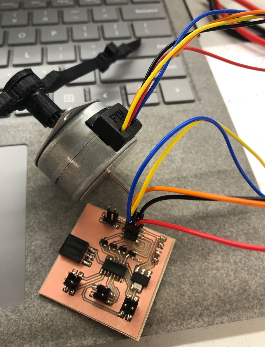
Eventually, the motor can rotate in the way that ATtiny 1614 tells it to go.
Group Assignment
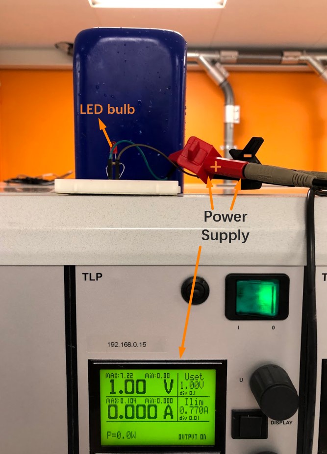
This week's group assignment is to measure the power consumption of an output device。For convenience, we measured the power consumption of a LED bulb under different voltages.
We used the TLP power supply that has been integrated in the electronic workbench, which not only serves as a safe power source but also directly displays the real time power consumptions.
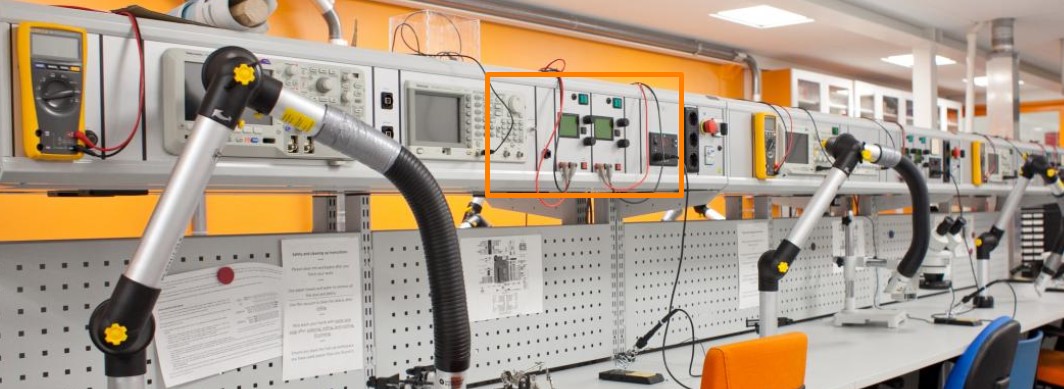
After connecting the LED bulb to the power supply, we begin to adjust the voltage.
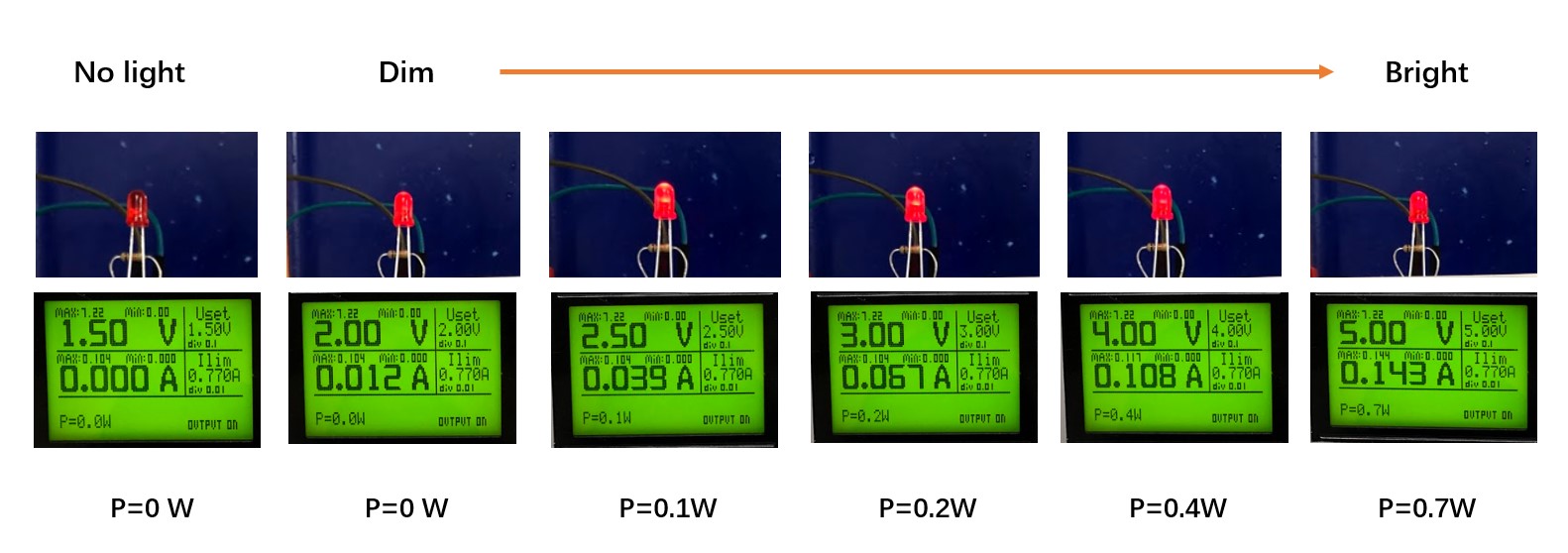
The power consumption under different voltages are as below. The LED start to light up at 2V and gradually light up as the voltage increases.
Files
LCD Arduino Code:
● Output Device Test Code
Final Files:
● ATTiny1614 Schematics
● ATTiny1614 Board
● Stepper Motor Control.ino