Group Assignment
The group assignment of week 3 focuses on characterizing our lasercutter's focus, power, speed, rate, kerf, and joint clearance. I have learned the basic knowledge about vinyl cutter and laser cutters, such as how to (1)operate, (2) calibrate, and (3) cut with these machines. More specifically, during the vinyl cutting tasks, I have learned how to extract the contour of the patterns to be cut. With the laser cutters, I have learned how different combinations of speed, power, frequencies, and DPI will lead to different cutting and engraving performance. Please check our Group Assignment Page for more details.
Individual Assignment
In this week, I have gained experiences with both the vinylcutter and lasercutter in Oulu FabLab. With the vinylcutter, I have made a sticker based on a SVG image, while with the lasercutter, I have created the parts for a Small stellated dodecahedron.
Vinyl Cutting
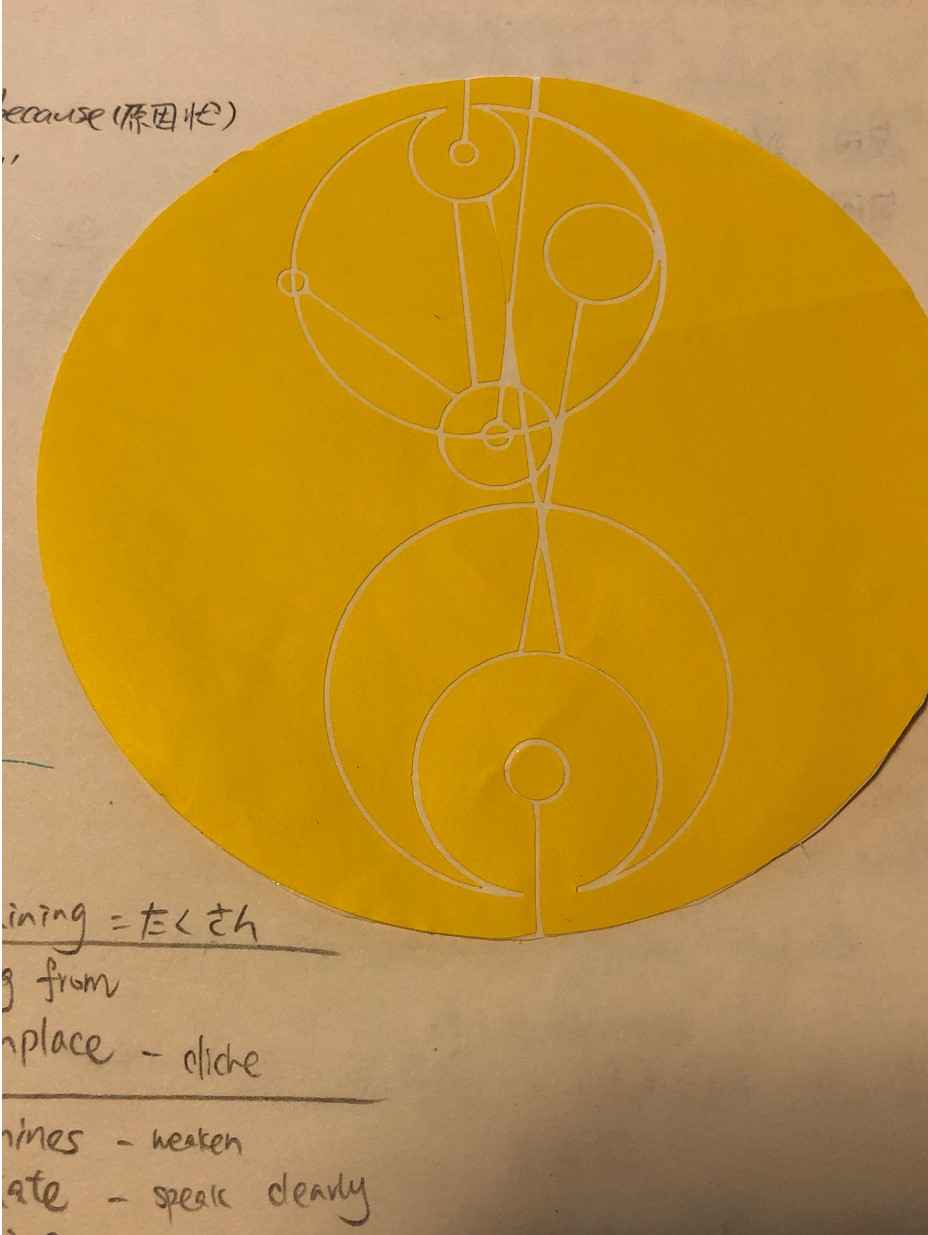
I have created a sticker that represents my name written in Gallifreyan with the viny lcutter. Oulu Fablab has a Roland GS-24 vinyl cutter that can make flexible circuits and crafts, such as signs, markers, adverts. The procedures are not complicated: creating the SVG image, printing it with the vinyl cutter, and then shearing off, instead of pulling off, the sticker.
Step 1. Create SVG Image
The pattern I chose has been my name written in Gallifreyan language. Gallifrey is a fictional planet in British TV series Doctor Who, which was the homeworld of the Time Lords. The Gallifreyan Language has a complex circular orthographic rule. So I used this open Translator to create the pattern.
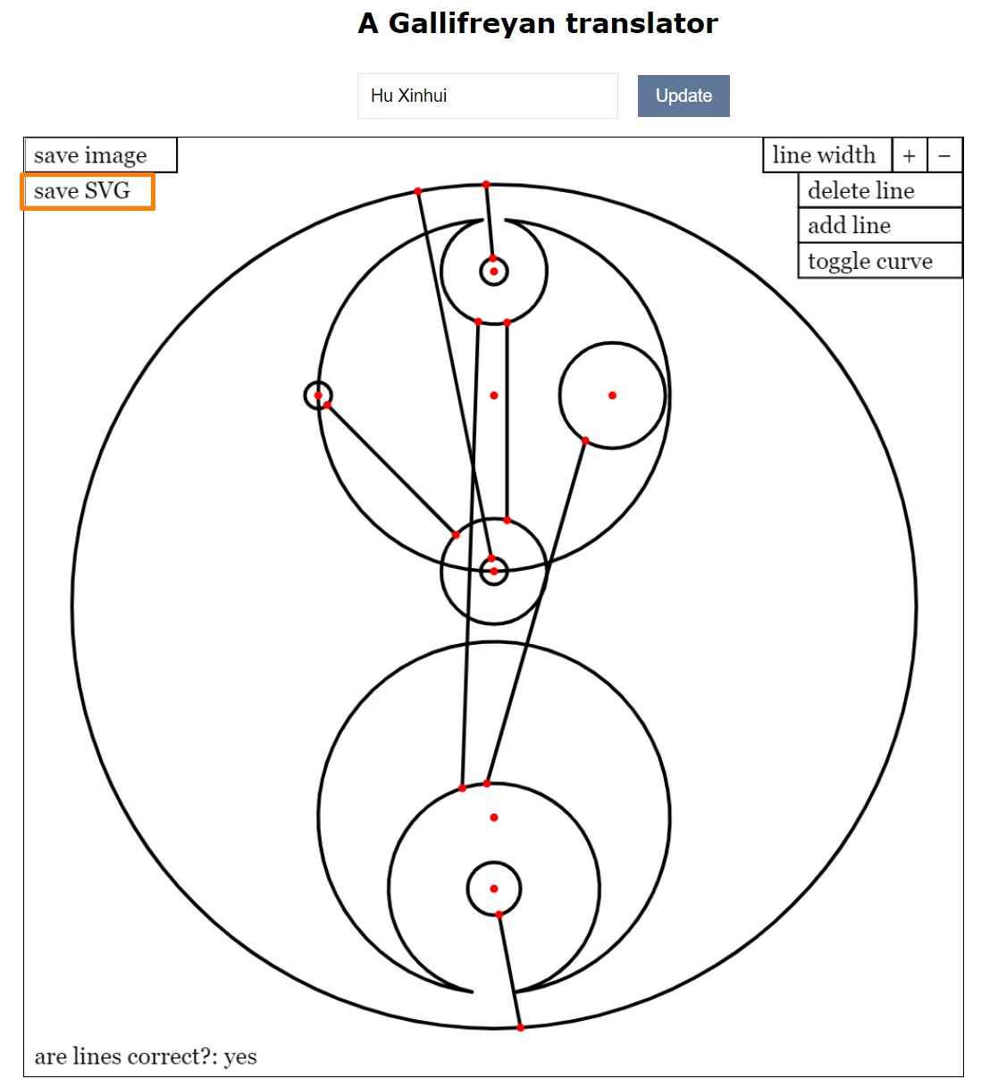
The next step was importing the SVG into corelDRAW or Inkscape for further edition. I have used CorelDRAW due to personal preference. Because the image has already been in vector format, there is no need for vectorizing the image. However, if needed, a raster image can be converted into vector via the function ofBitmaps >> Outline Trace .
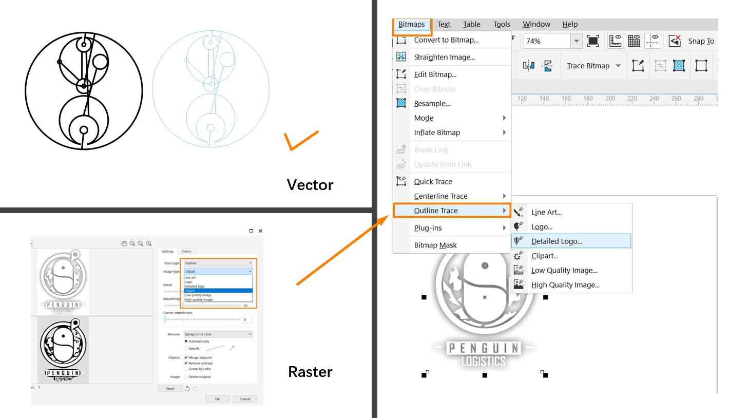
The line width was set at 0.2 mm. After finishing the adjustment, drag the image to the CutStudio software and right click for contour detection. If the line detection works well, the image is ready for vinyl cutting.
Step 2. Vinyl Cutting
Several operations need to be done for the vinyl cutting:
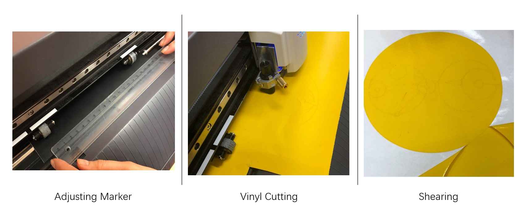
1. Release the loading lever to insert the vinyl film
2. Adjust the pinch rollers by aligning them with the appropriate white markers
3. Pull down the loading lever, choose the modes, and press Enter button to load the film
* After loading the material, users should choose from 3 options:roll/edge/piece, so a sensor is located on the carriage will specify the szie of the material for the machine.
● Roll: the machine will treat the inserted material as a roll of vinyl film
● Edge: the machine will measure the width of the material
● Piece: the machine will measure both the width and length of the sheet
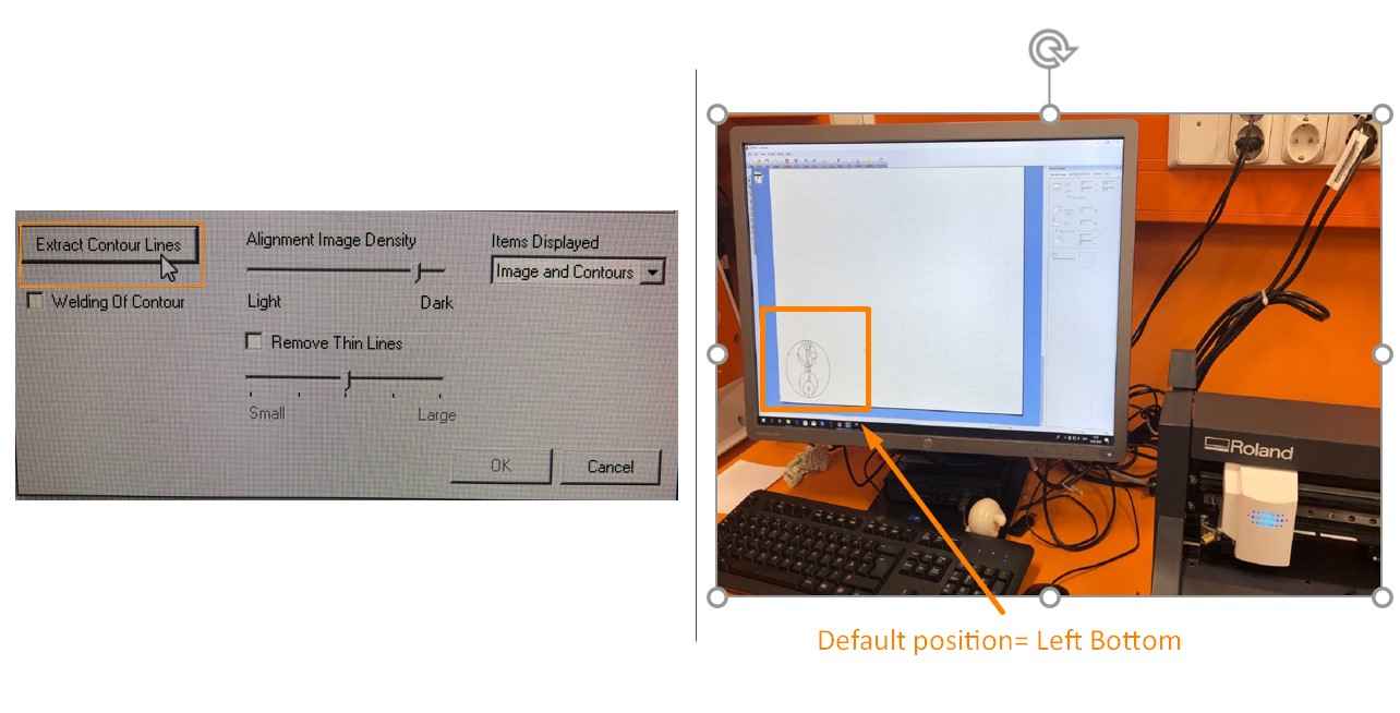
4. Set the origin of the vinyl cutter or go by default (Left Bottom)
5. Print the image from the CutStudio interface
Step 3. Shear and Transfer
It is highly recommended that the sticker should be sheared off with tweezers instead of being pulled off. Because pulling the sticker may damage the delicate parts. A transfer sheet is very helpful in transfering the sticker from the vinyl film to another surface. In my case, I used the transfer sheet to transfer the sticker onto my notebook. It is also possible to transfer the cut vinyl film to t-Shirt and other fabrics here at Oulu FabLab.
Major Takeaway for Vinyl Cutting
I. Reflection:
In general, I think vinyl cutting is a process that is full of creativity and innovation.
II.What I have learned:
1. Vectorize image
2. Adjust the vectorize image and abstract the outline of image for vinyle cutting
3. Adjusting and manipulating the vinyl cutter
III. Problem Encountered and Solved
My experience with vinyl cutter was quite smooth, which may be due to that the image I used was vector. But I do had a good practice with vectorizing raster image and abstracting their outlines.
Parametric Design
Parametric design refers to the design process that we create objects by specifying parameters, and depending on changing the value for these parameters our design responses accordingly.
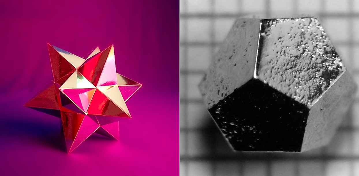
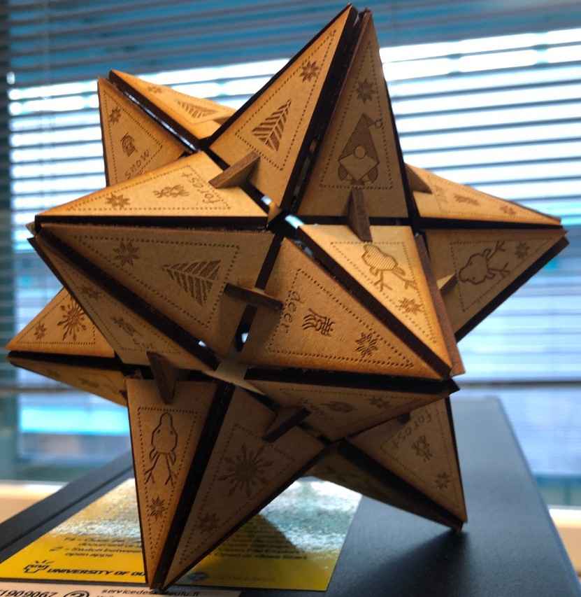
I have chosen to make a Small Stellated Dodecahedron for the parametric design task.
The reason for me to choose to make a small stellated dodecahedron has been that this is an object that seems complex but can be created with simple calculations, as the entire surface of a stellated dodecahedron has consisted of identical triangles. There is also a free onlineSmall Stellated Dodecahedron Calculator available that can help users to calculate the length of edges. However, since the mathematical models do not disclose much about the inner support structure of a stellated dodecahedron while I hope to find the proper size for this model, I have taken the model of JMazzy for a reference.
From JMazzy's design, I figured out that a Regular dodecahedron will be used as the support structure inside the stellated dodecahedron.
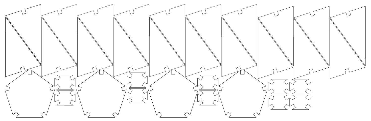
According to the mathematical model and JMazzy's design, I only need to design three different shapes:
● A regular pentagon
● An isosceles triangle
● A joint piece that connects triangles and pentagons
Parameter Definition
After I got the basic knowledge of the structure of stellated dodecahedron model, I started my parametric design with Fusion 360.The first step is defining the necessary parameters. In my case, three parameters need to be defined, which are material thickness, kerf, and slot width.
The parameter setting interface can be accessed via the path of Top Menu >> Modify >> Change parameters
In my case, a strong focus of my parametric design has been dealing with the material thickness, kerf, and slot-width.
As discussed in the Group Assignment, the laser beam itself has a certain width, which means it will burn more material than expected when it cut through. Thus, the slot will be wider while the tab will be thiner than it should be. Thus, it is important to include the kerf in calculating the parameters in a laser cutting design.
* If the measurements the kerf is not consistent, you can also refer to the average kerf.
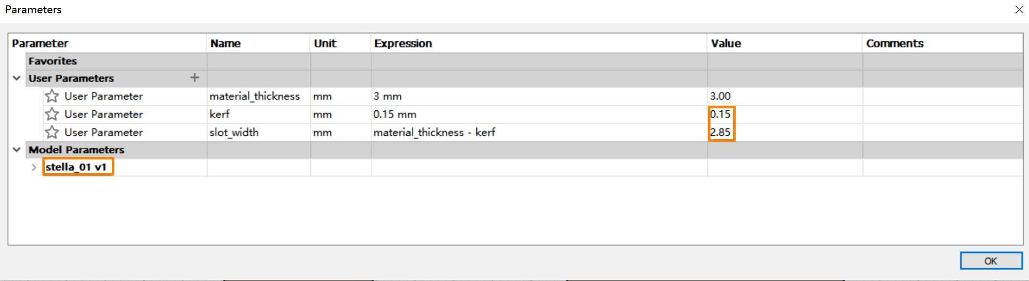
Press the "+" sign in the User Parameter tab to define the parameters.
                ●   material_thickness=3 mm

                ●   kerf=0.15mm

                ●   slot_width= material_thickness - kerf
It is highly recommended to define the parameters in the form of functions or equations. Thus, when adjusting a certain parameter, all the related ones will be automatically changed accordingly, which is the beauty of the parametric design.
Pentagon
My experience of parametric design starts with pentagons. Totally 12 identical pentagons will be needed to support a stellated dodecahedron, but I actually only need to design one of them and then print the shape for 12 times.
I created the pentagon following this path:
Create Sketch >> Choose "Top" platform >>Create >> Polygon >> Edge Polygon
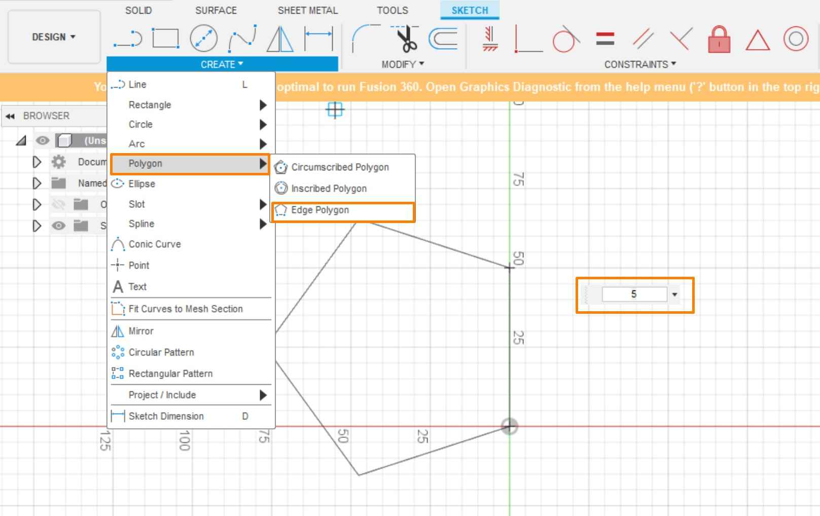
The following steps include:
1. choose the start point
2. define edge length (which is 25 mm according to JMazzy)
3. enter 5 as the number of edges.
Then a regular pentagon is created.
Then, a slot needs to be created at each tip of the pentagon. The Center Rectangle function is quite useful in this case. This function allows user to create a rectangle by specifying the center point, height, and width values of the rectangle.
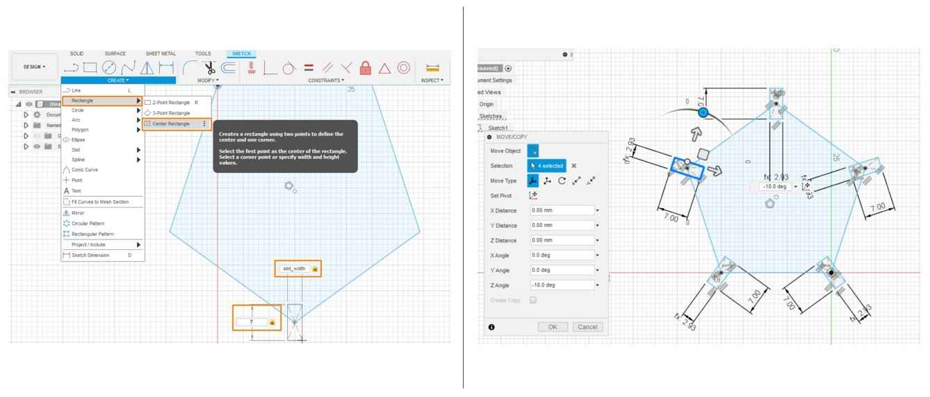
This task can be finished with the following steps:
1. Access the Center Rectangle function via Create >> Recntangle >> Center Rectangle
2. Select one tip of the pentagon as the center
3. Type the parameters to define the height and width
                       width=slot_width

                       height=7 mm
And repeat the same procedures for all the tips of the pentagon. The additional lines should be trimmed from the pentagon. However, Fusion 360 will automatically subtract the slot.
Triangle
Sixty identical isosceles triangle pieces need to assemble the surface of the stellated dodecahedron.
The base of each triangle are preset and all other calculation are based on these parameters.
base width= 30mm
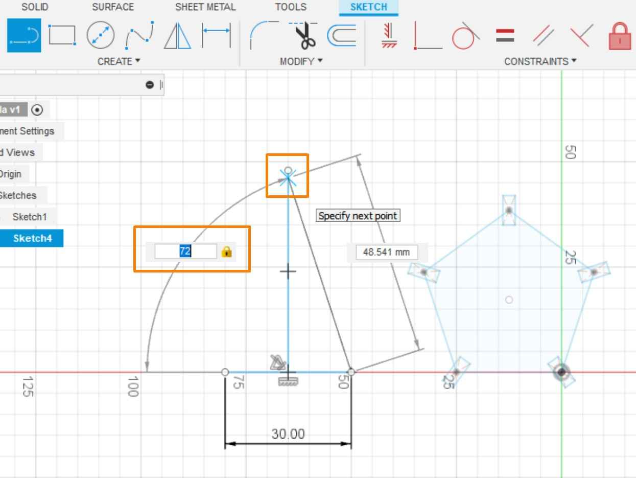
Because the triangle will be specified by base length and angles, the line function should be used here instead of the polygon function.
bottom angle = 72°
This task can be finished with the following steps:
1. Select the start point and input 30 as the parameter for the base length
2. Draw a vertical line through the middle point of the base
3. Draw a line from one end of the base line and set the degree as 72
4. Set the point where the tilted line meets the vertical line as the top of the triangle
5. Connect the top point and the other end of base
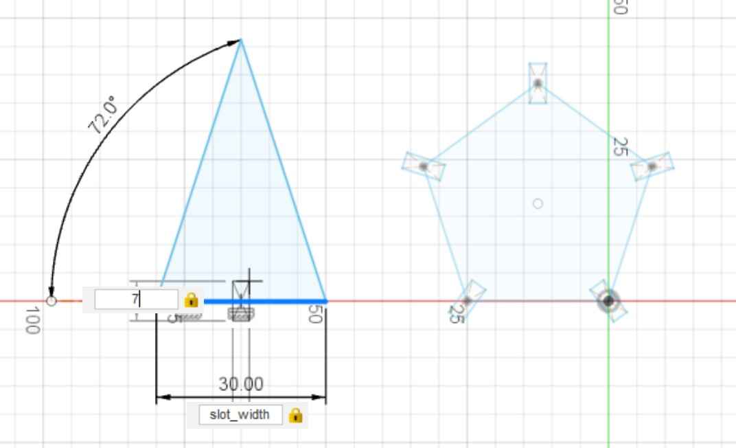
Creating the slot on the triangle requires similar operation as the pentagon.
Create Center Rectangle >> Select midpoint of base as center >> input slot width and height
Each triangle only needs one slot at the center of the bottom edge.
Joint Pieces
The height and width of the joint piece is not very strict, as the pieces do not need to perfectly touch with each other. In my case, the height and width are slightly larger than necessary, but the final outcome seems to be fine.
The joint piece starts from making a rectangle with:
                      height= 12 mm

                      width = 17 mm
Creating the joint pieces's slot actually take more effort. In this case, each joint piece should have four slots that tilted by 60 degrees because the angle between two sides of the stellated dodecahedron is always 120 degrees. This task takes several steps to accomplish.
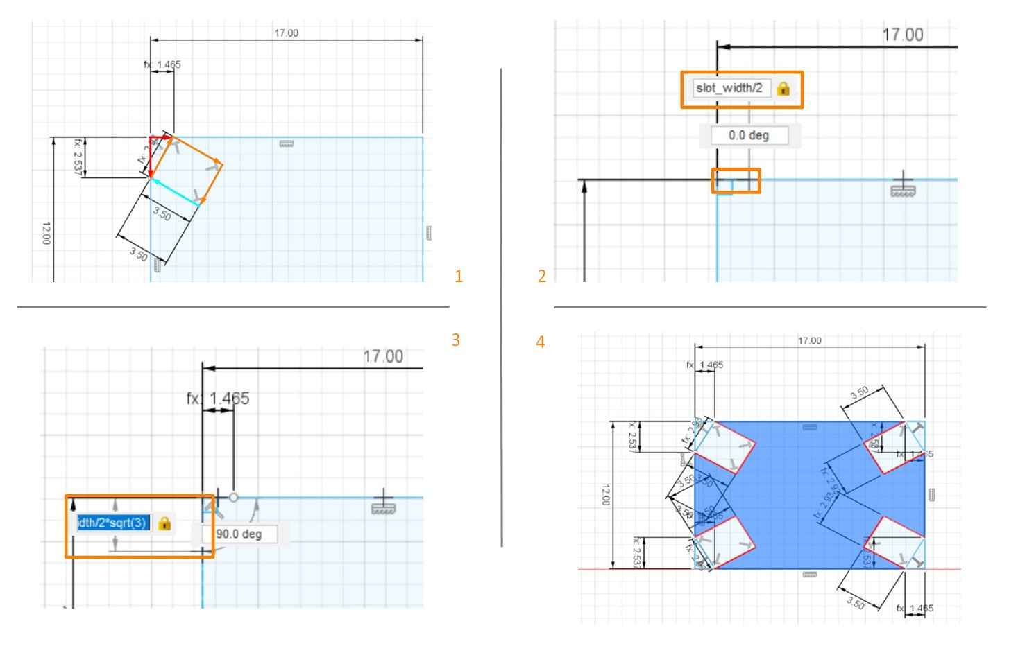
Step 1: Calculation:
As shown in the upper left image, the strategy of creating the slot is mainly based on the Pythagoras theorem. The slot_width serves as the hypotenuse of the right triangle. Knowing that the other two angles are 30 degrees and 60 degrees, it is possible to determine the start point of the slot at each edge.
                      short right side= slot_width/2

                      long right side = (slot_width/2)*sqrt(3)
Step 2: Start from one tip of the rectangle, draw the short and long right sides
* These formula should be directly input as parameters
Step 3: Connect the end of the two sides so the hypotenuse (slot width) can be specified.
Step 4: Add the depth(7/2) to the slot and complete the contour
Repeat the same procedures for all the other angles of the joint piece.
Tips:
It is very easy to mistakenly use the Center Rectangle function to make a rectangle and rotate it for creating the slot, which is the strategy for the previous two cases. However, slot width serves as the hypotenuse this time so the center of the slot is not at the tip of the rectangle. So location should be defined with Pythagoras theorem.
Export and Decoration
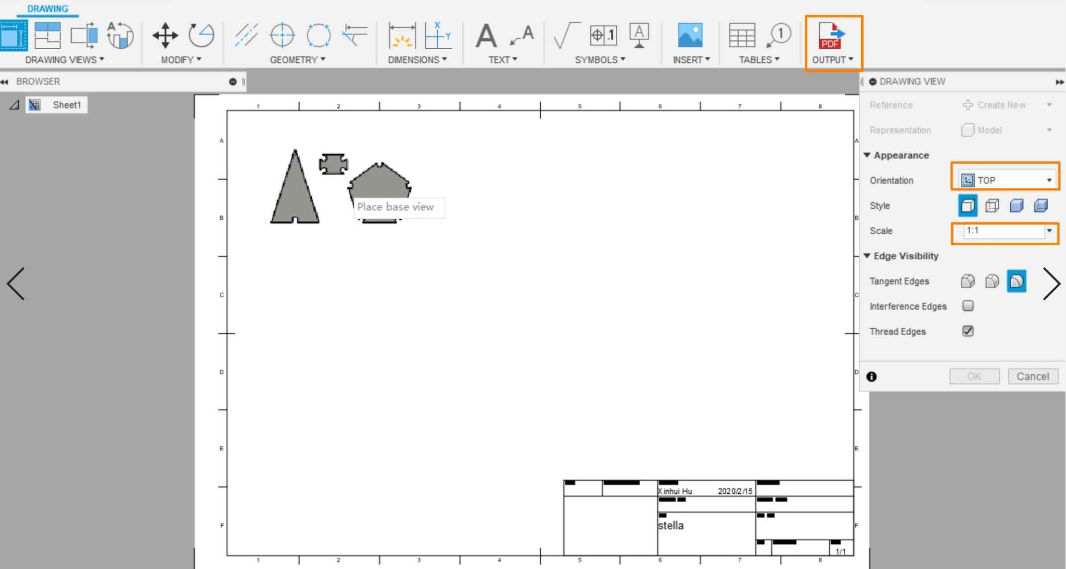
While all the pentagons, triangles, and joint pieces have the exact same shape and size, ten different patterns have been designed for decoration. Thus, my strategy has been that export the design from Fusion 360 and then add the decoration in CorelDraw. To export the PDF of the model, the Drawing Function is a good choice.
The Drawing function can be accessed via Top Menu >> Drawing >> Drawing From Design
When enter the Drawing Interface, select the appropriate view and place the shapes on the canvas.
Click "Output as PDF" on the top menu bar so the shapes can be exported.
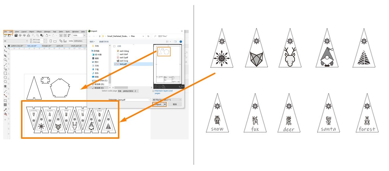
The decoration has been done in CorelDRAW.
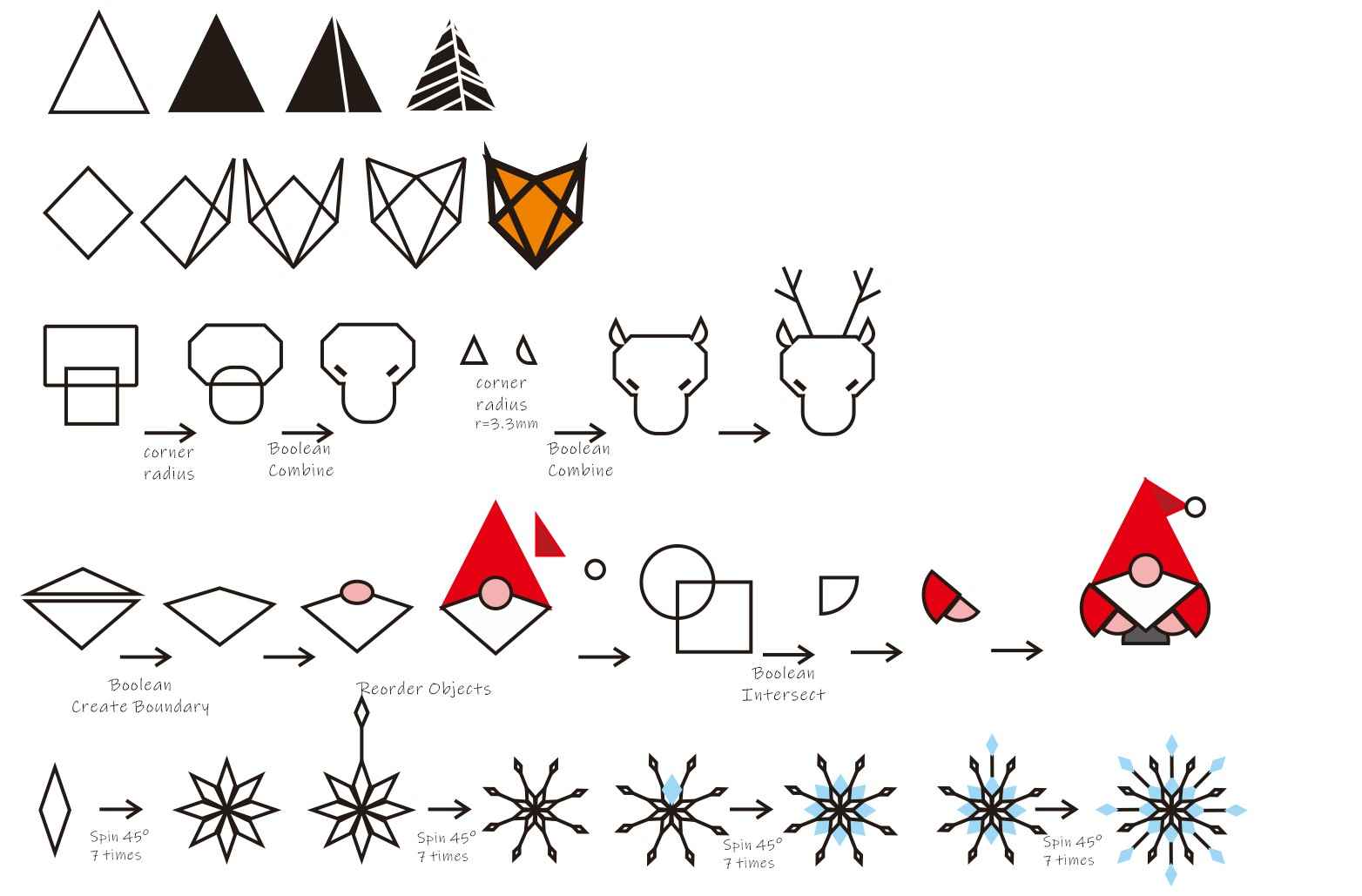
In design the patterns, I hope to present both Finland (where I stay) and Chinese (where I come from) features. So I choose five things that I think are very closely associated with Finland: snowflakes, fox, deer, Santa, and forest. By combining common shapes with simple Boolean calculation and Rotation, I was able to make the icons for these features. On the other hand, I used the second oldest version of Chinese Character, Zhuan, to write the names of these features. So there are 10 different patterns in total.
Directly import the PDF from Fusion 360 to CorelDRAW, it will recognize the vectors. The next step is fitting the patterns in the triangle shapes, the borders of these shapes need to be adjusted for laser cutting. Because my pattern has both raster and vector elements, so it will be in the Combined Mode that both engrave and cut through.
In order to make the distinction for the machine, all the lines that supposed to be cut through should be 0.02 mm or close to 0.02 mm , while all the lines for engraving should be thick enough.
Major Takeaway for Parametric Design
I. Reflection:
In general, I think parametric design is a great strategy for object design, which is not only precise but also convenient when iterating the parameters. With parameters, all the interdependent data will automatically change, which is much more convenient and less error-prone than manually change everything.
II.What I have learned:
1. Define objects by assigning parameters and the rules that confine the parameters
2. Create complex object by combining different parametrically design objects
3. Add necessary constraints to the parameters to make them behave stable when other parameters change
III. Problem Encountered and Solved
As discussed above, the most challenging part for me may be define the slots on the joint piece, because it is really easy to mistakenly follow the right strategy and simply rotate the rectangle. This problem is solved by applying Pythagoras theorem. Another problem was that the kerf I used at the first time was too small, which makes the pieces loosely fit with each other. After adjusting the kerf to 0.15mm, the pieces are connected well.
Laser Cutting and Kit Assembling
After adjusting the line thickness, the project is ready to be processed by the laser cutter. In order to save the materials, it is highly recommended to use to "Resize Document" function to reduce the white space surrounding the figures.
This function can be accessed via File >> Documentary Property >> Resize Document
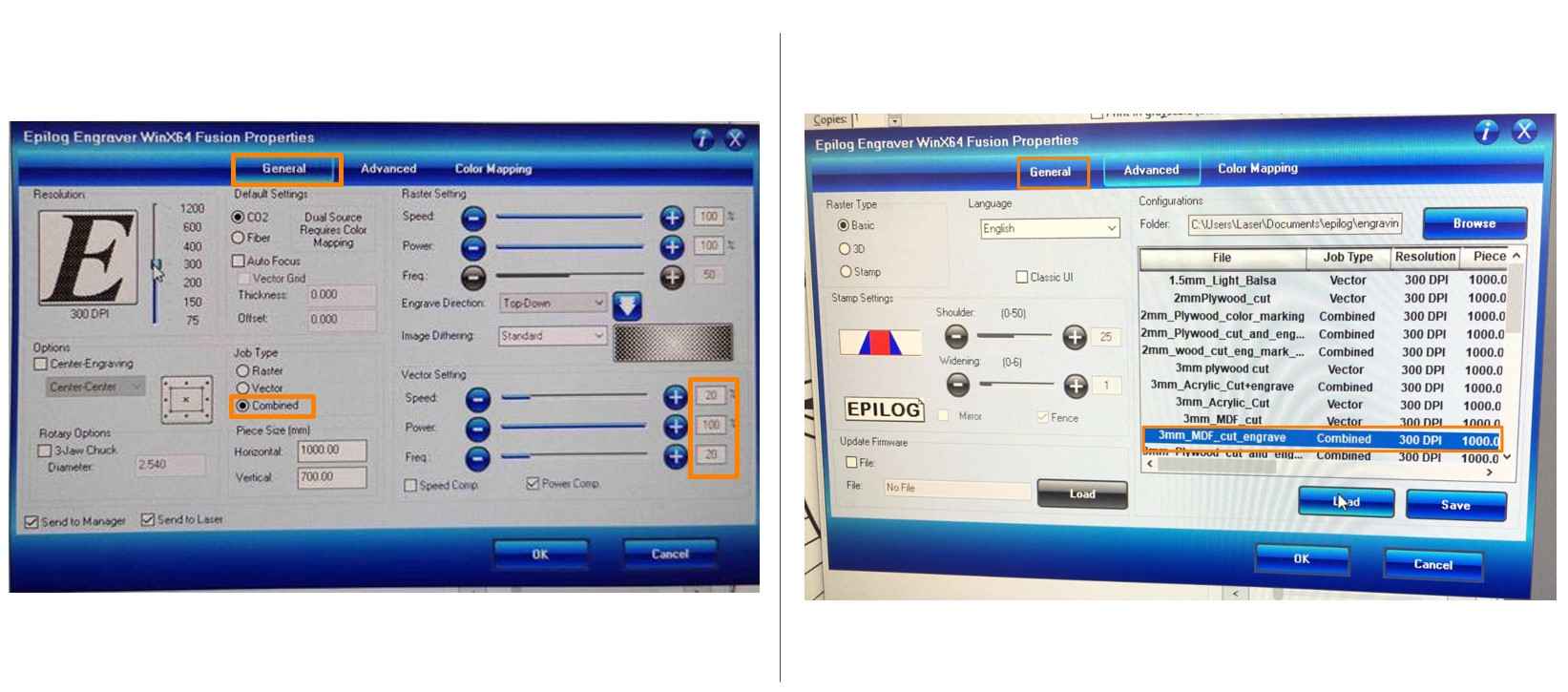
An Epilog Laser Fusion laser cutter is used in Oulu FabLab. The procedures of operating this machine is straightforward. To start the machine, two switches on the wall: one for energy and one for air-duct, need to be turned on first, and then the switch on the lower right part of the machine should be turned on. On the panel, there is a button labelled with a red radition icon, turn it on will allow the machine show the aim location of the laser beam.
First, the printing document should be sent to the machine with approporiate configurations. Because I am using 3mm MDF for both engraving and cutting, I loaded the corresponding setting. Becuase I would like to cut through the contour of my shapes, I have chosen set Speed at 20%; Power at 100%; Frequency at 20%.
Then next step is to manipulate the laser cutter.
Never turn your sight away from the laser cutter when it is working!
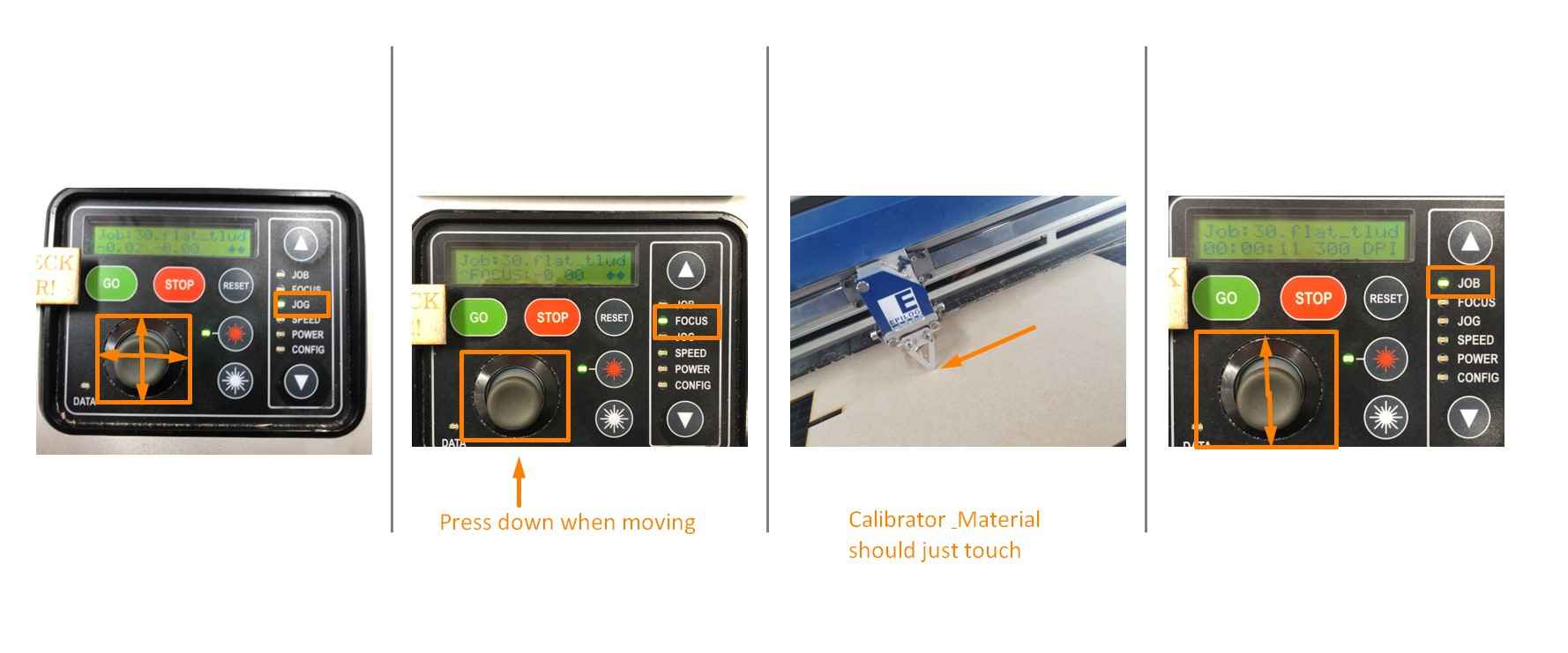
1. Select Jog on the control panel and adjust the start point, press the joystick to set the start point.
2. Select Focus on the panel and adjust the focus with Focus Calibrator or use the autoadjustment. If using the calibrator, its tip should just touch the material surface.
3. Select Job on the panel to choose the file to be print and then press the Go button.
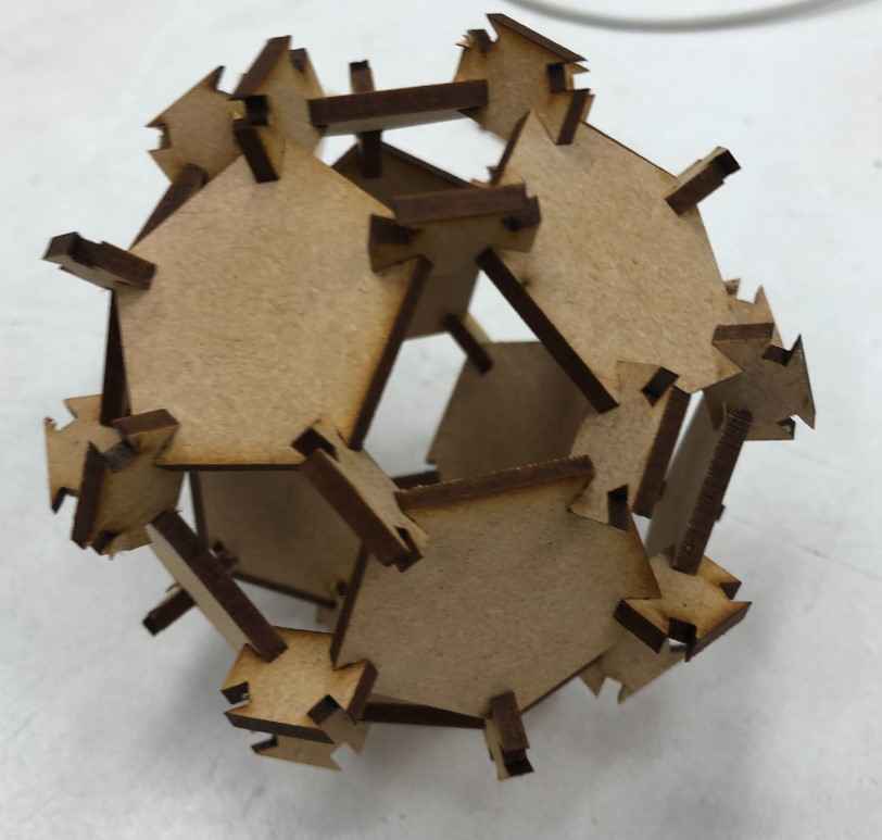
After cutting 60 triangles (5 sets), 12 pentagons, and 20 joint piences, the kit is ready to be assembled.
The pentagons should be first assembled into a regular dodecahedron. Each pentagon should be paired with 5 triangles.
Major Takeaway for Laser Cutting
I. Reflection:
In general, I think the laser cutter in Oulu FabLab is very user-friendly, which can be adjusted and used with simple operational procedures.
II.What I have learned:
1. Create appropriate image for laser cutting
2. Adjust the parameters for laser cutting
a. laser properties: speed, power, frequency, dpi...
b. material: MDF, acrylic, metal...
c. task type: engrave, cut, combined...
3. Manipulate laser cutter
a. adjust start point
b. adjust focus
c. select task files
III. Problem Encountered and Solved
As discussed above, the most challenging issue in this case was to determine the right number for kerf. The kerf I used at first was too small, which hence made the pieces fit loosely with each other. The other part are quite straight forward and delightful. Another tiny issue that may be note worthy is that lines thinner than 0.02mm will be processed in the cut mode. So it is important to make sure that the lines that are designed to be cut to has a thinner width and vice versa.
Files
Vinyl Cutting:
● Vinyl Cutting Pattern.SVG
Laser Cutting:
● Parametric_Design.STL ● Parametric_Design.F3D
● Exported_Shapes.PDF
● Triangle_Printable.PDF
● Pentagon_Joint Piece.PDF