7. Computer-controlled Machining
Week’s Assignments
Group Assignment:
● Test runout, alignment, speeds, feeds, and toolpaths for your machine.
Individual Assignments:
● Make (design+mill+assemble) something big
Group assignment
Group:
● - Xinhui Hu
● - Zhengya Gong
● - Yazan Barhoush
● - Noora Nyberg
For this week, Eino gave a comprehensive tutorial on the subject, including creating a file, setting the tools paths and exporting it for milling, using CNC Router and safety issues.
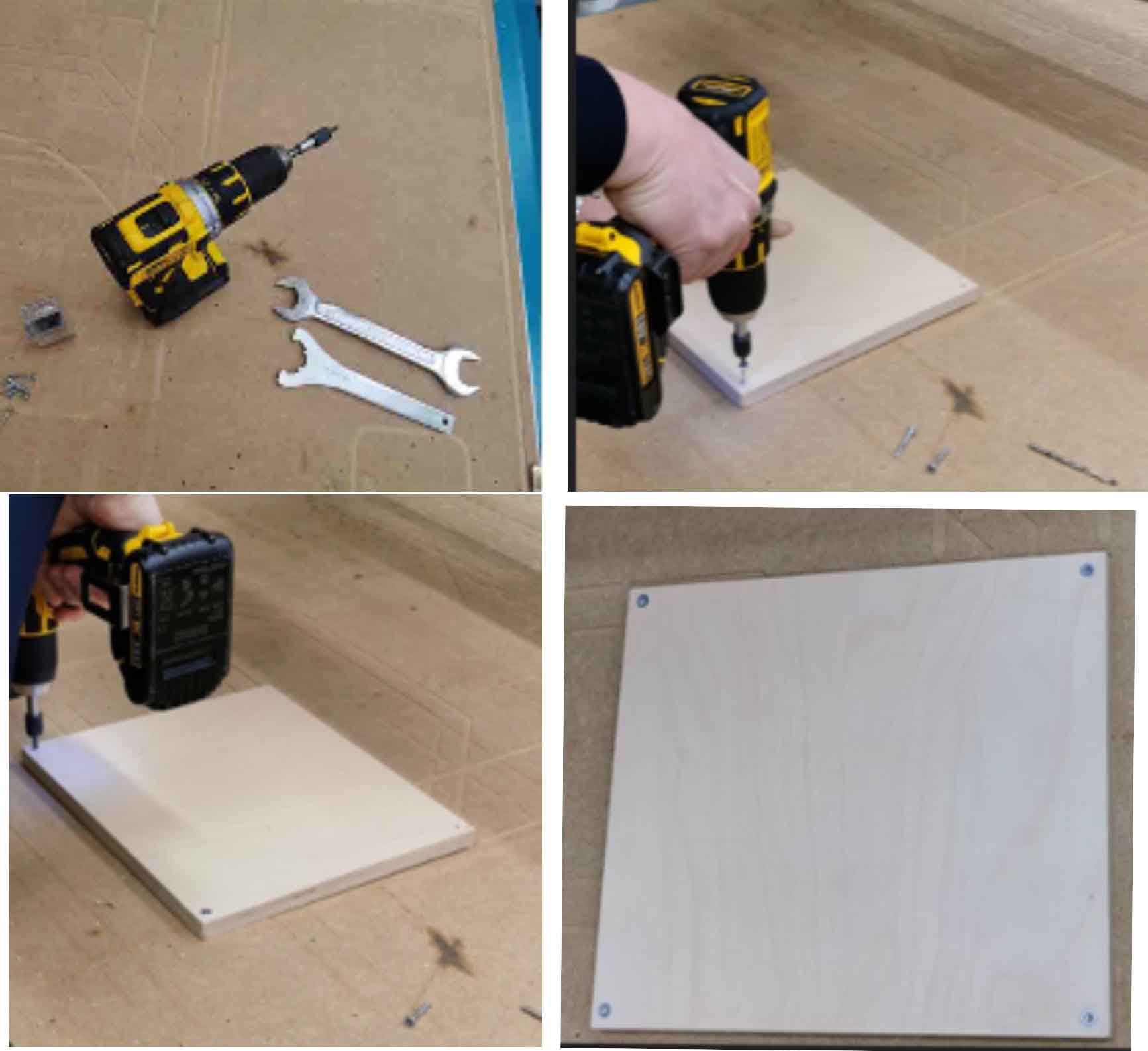
● Step1. Placing the milling bit. Since the milling bit, which was already installed on the machine, was a 8mm flat one, so we did not need to change the milling bit. we checked the milling bit and tighten the screws.

● Step2. Screwing the board.
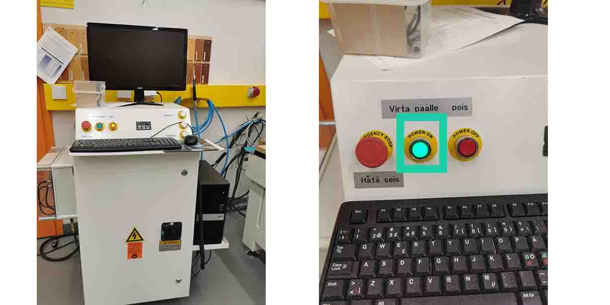
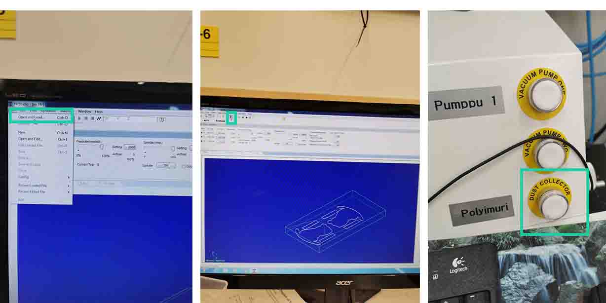
● Step3. Setting the X, Y and Z origins. To accomplish that, we powered on the machine. The following figure shows the buttons on the machine. Then, we started the NcStudio software from a computer. The CNC router machine was controlled by a computer located next to the machine.
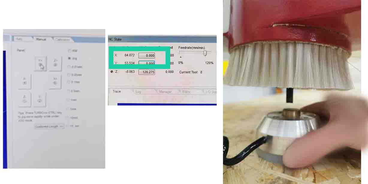
For the X and Y axes, just move the header to the desired position (be careful with the screws), and then use the W.Coord button for the X and Y in the software to set the origin. There is also an automatic calibration method for the Z axis. In this approach, we put the mobile calibrator just underneath the milling bit. Next, start the calibration process from Operation > Mobile Calibration in the software. The milling bit will move down until it touches the metal surface of the mobile calibrator, and it will automatically set the origin for the Z axis to that point.
● Step4. Opening and loading the .nc file, from File > open and load. Then, we clicked on simulation button to see if everything is OK. Next, the feedrate and Spindle values were reduced respectively to 80% and 80% of their values, in order to increase the quality of the milling process and press the dust button. Finally, we pressed the play button to start the milling process and increase the feedrate and Spindle values to 100%.

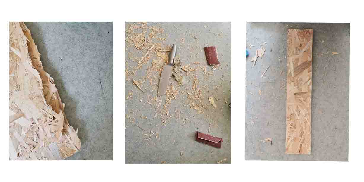
● Step5. After milling, we cut the outline by knife.

● Step6. We used another machine to polish the edges, to make the outline smoother.

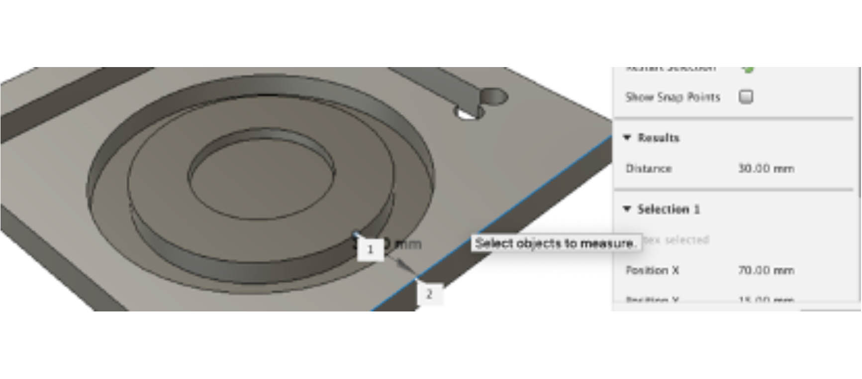
● Step7. We used a Caliper and a Tape measure to measure dimensions of test part.

● 1.
Measure instrument: Tape measure Designed distance: 200.0mm Measured distance: 200.0mm Difference: 0.0mm

● 2.
Measure instrument: Tape measure Designed distance: 200.0mm Measured distance: 200.0mm Difference: 0.0mm

● 3.
Measure instrument: Caliper Designed distance: 55.0mm Measured distance: 54.20mm Difference: 0.8mm

● 4.
Measure instrument: Caliper Designed distance: 100.0mm Measured distance: 100.0mm Difference: 0.0mm

● 5.
Measure instrument: Caliper Designed distance: 130.0mm Measured distance: 129.1mm Difference: 0.9mm
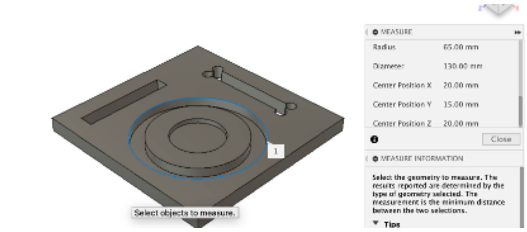
● 6.
Measure instrument: Caliper Designed distance: 5.0mm Measured distance: 5.0 mm Difference: 0.0mm
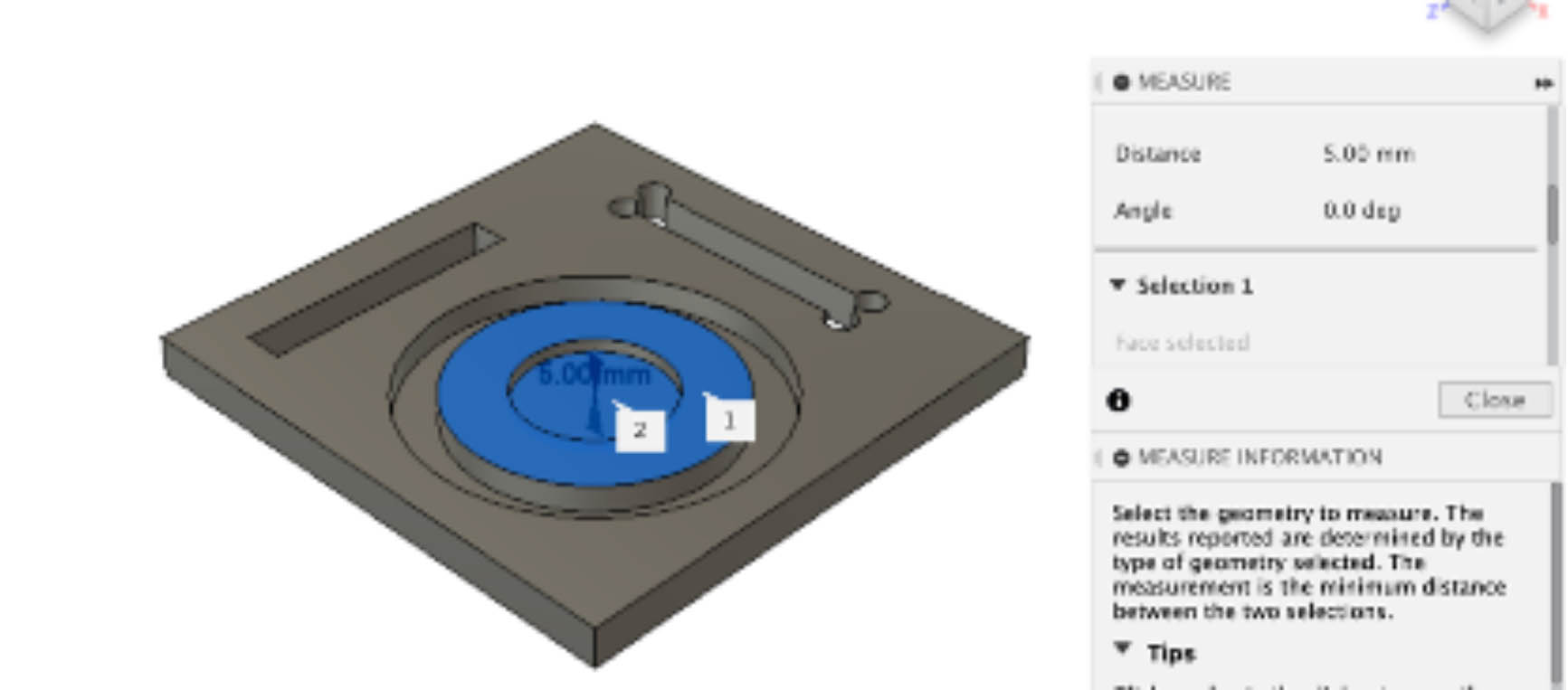
● 7.
Measure instrument: Caliper Designed distance: 10.0mm Measured distance: 10.0 mm Difference: 0.0mm

● 8.
Measure instrument: Caliper Designed distance: 100.0mm Measured distance: 99.2 mm Difference: 0.8mm

● 9.
Measure instrument: Caliper Designed distance: 15.0mm Measured distance: 14.2 mm Difference: 0.8mm
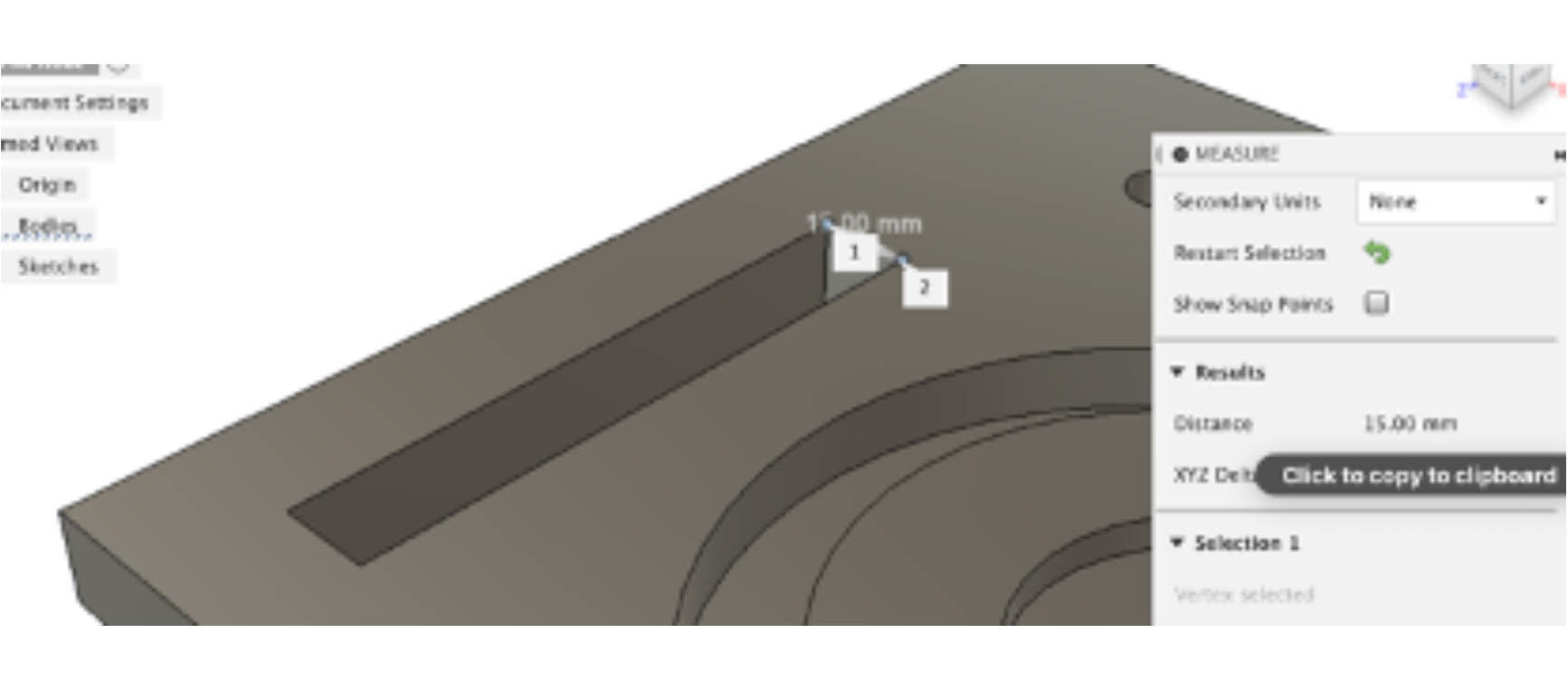
● 10.
Measure instrument: Caliper Designed distance: 100.0mm Measured distance: 99.6 mm Difference: 0.4mm
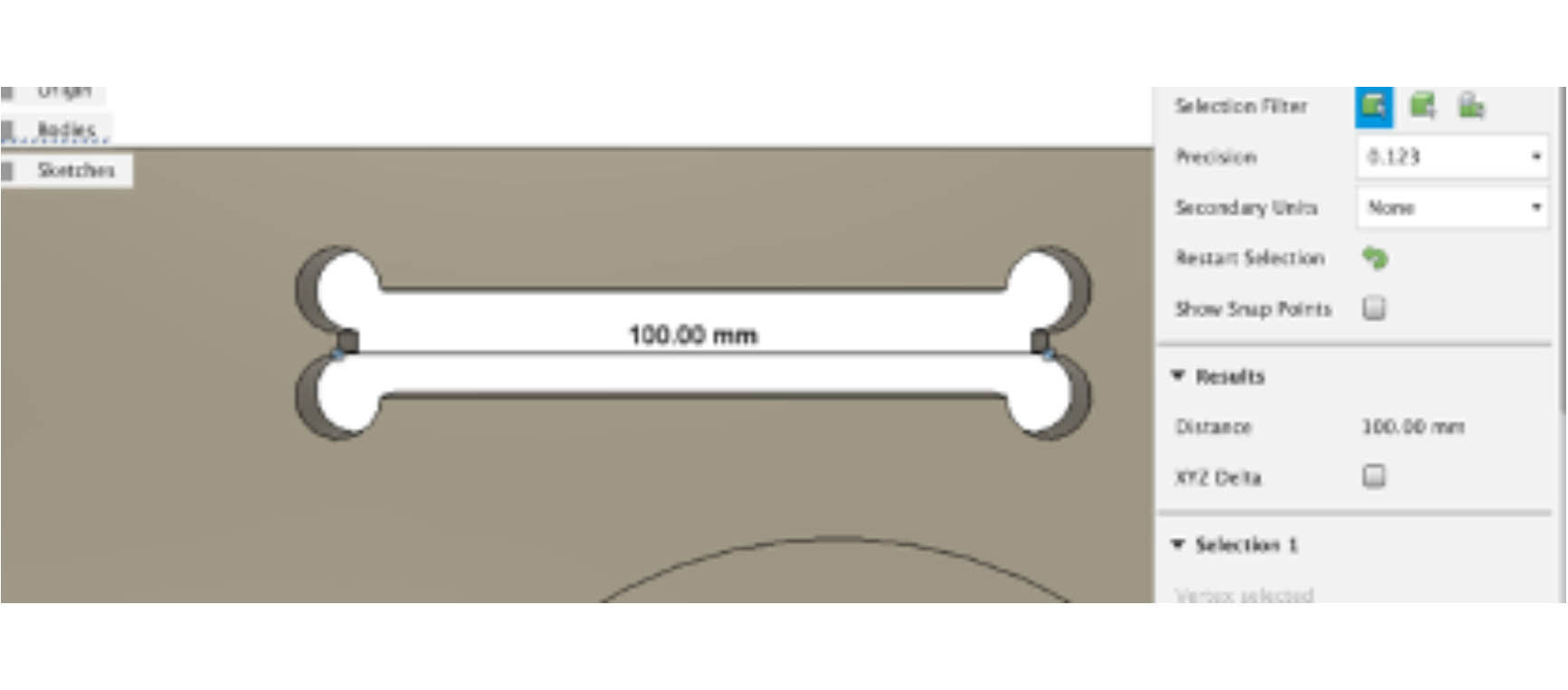
● 11.
Measure instrument: Caliper Designed distance: 15.0mm Measured distance: 15.4mm Difference: 0.6mm

● 12.
Measure instrument: Caliper Designed distance: 12.0mm Measured distance: 11.4mm Difference: 0.6mm
● 13.
Measure instrument: Caliper Designed distance: 52.5mm Measured distance: 52.5mm Difference: 0.0mm
● 14.
Measure instrument: Caliper Designed distance: 165.0mm Measured distance: 165.0mm Difference: 0.0mm

● 15.
Measure instrument: Caliper Designed distance: 50.0mm Measured distance: 50.0mm Difference: 0.0mm
● 16.
Measure instrument: Caliper Designed distance: 15.0mm Measured distance: 15.0mm Difference: 0.0mm
● 17.
Measure instrument: Caliper Designed distance: 30.0mm Measured distance: 30.0mm Difference: 0.0mm
● 18.
Measure instrument: Caliper Designed distance: 20.0mm Measured distance: 20.0mm Difference: 0.0mm

● 19.
Measure instrument: Caliper Designed distance: 165.0mm Measured distance: 165.0mm Difference: 0.0mm

● Measured dimensions 3, 5, 8, 9, 10, 11, 12 are different from designed dimensions but rest of measured dimensions are same with designed dimensions.
Conclusion of group assignment
Assumedly problem is inaccuracy of Inside small jaws (Caliper) not milling process. Hence milling process was accurate.
Individual Assignments:
Designing a Big 3D Model
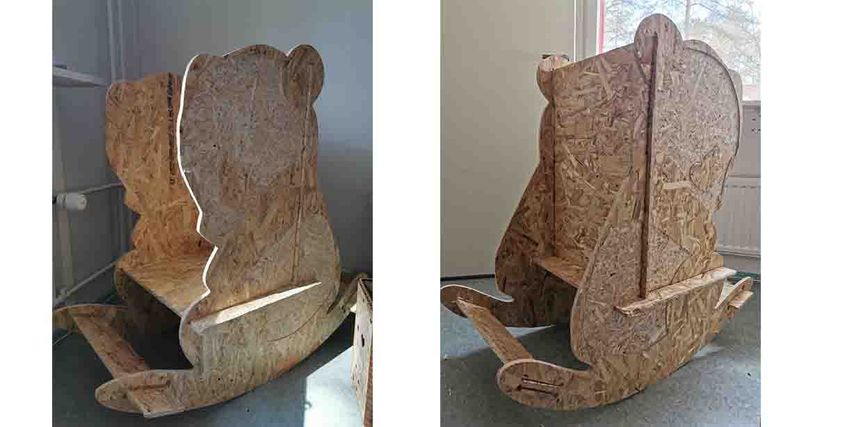
For this week’s task, we have to design something big to build with a CNC milling machine in Fab Lab. The material suitable for us is an 11 mm thick oriented standard board. I decided to design a panda rocking chair as a gift for myself. Because I have learned the operation of the Fusion 360, this week I decided to use it to design a panda rocking chair.
Design
● Step1. Create >> Fit Point Spline to draw the outline of the panda.

● Step2. Create >> Fit Point Spline to draw the lines inside of the panda.

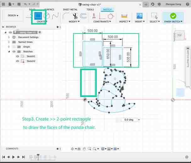
● Step3. Create >> 2-point rectangle to draw the faces and pedals of the panda chair.
● Step4. Create >> 2-point rectangle to draw the joints.
● Step5. Create >> center diameter circle to draw the circles, the reason that I draw the circle is because the milling bit that when it is milling the corner, it can not grind out the right angle,and it will lead to my chair cannot be well combined.

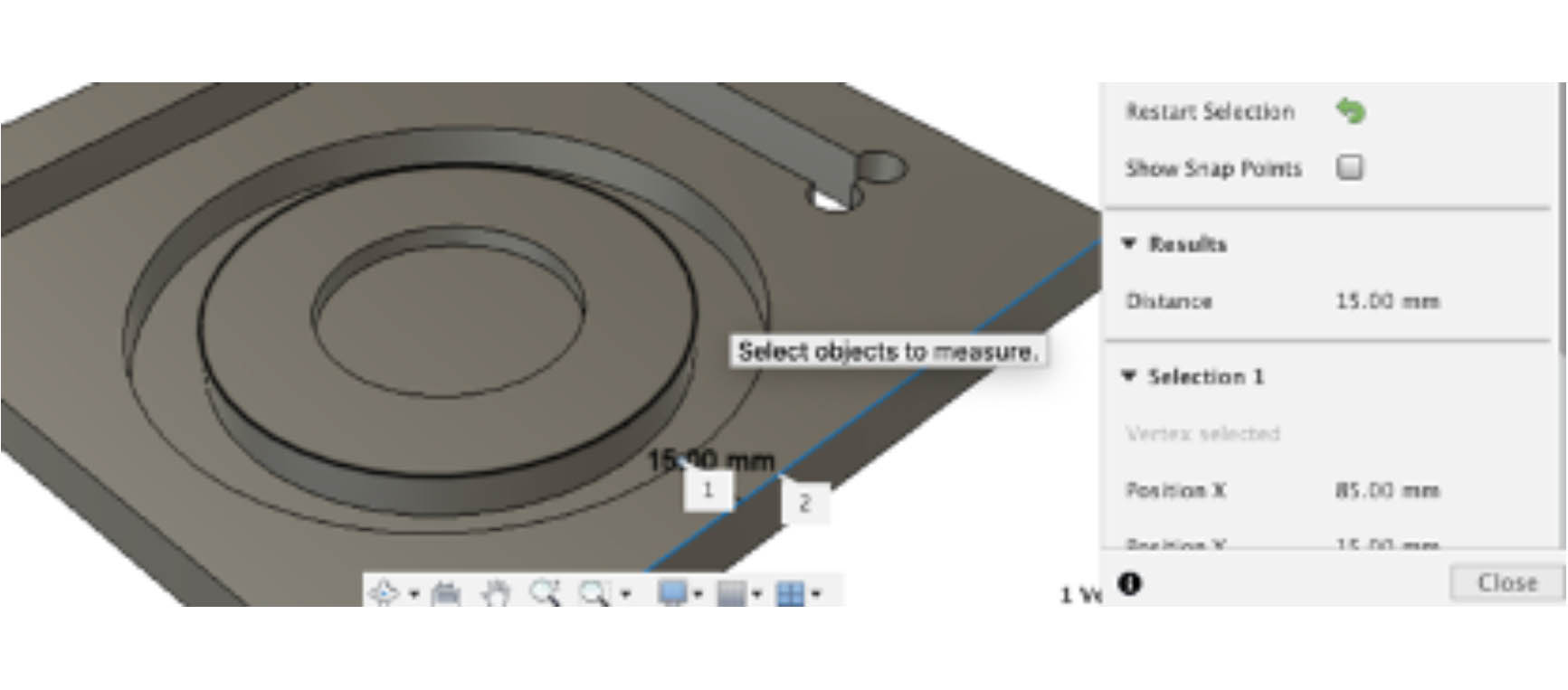
● Step6. Modify >> Trim to delete the lines. In this figure, it is clear to show the diameter of the circle is 15.00mm, and the diameter must more than 8.00mm, which is according to the milling bit. In this case, the milling bit is 8.00mm.

● Step7. Click to select it and right-click to choose Move/copy.
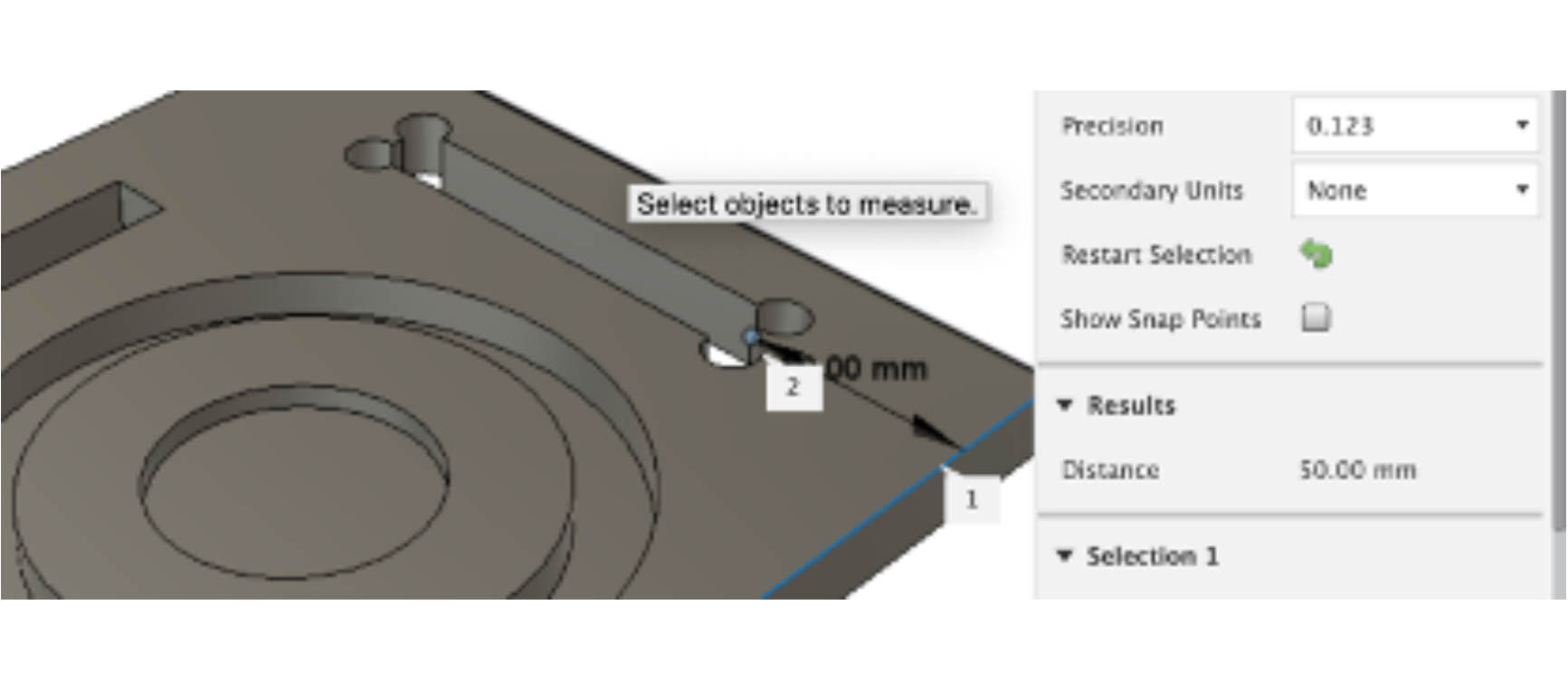
● Step8. Click to select it and right-click to choose Move/copy to move it one by one. In the following figure, the depth of the bone shape is 21.00mm, that because the thickness of the cutting board is 11.00mm, and I stacked two fiberboards on the pedals to make it’s more stable. Also, I hope the junction is tighter, so I set the depth to be 21.00mm.

● Step9. Create >> 2-point rectangle to draw the joints.
● Step10. Create >> center diameter circle to draw the circles.
● Step11. Modify >> Trim to delete the lines.
● Step12. Click to select it and right-click to choose Move/copy.
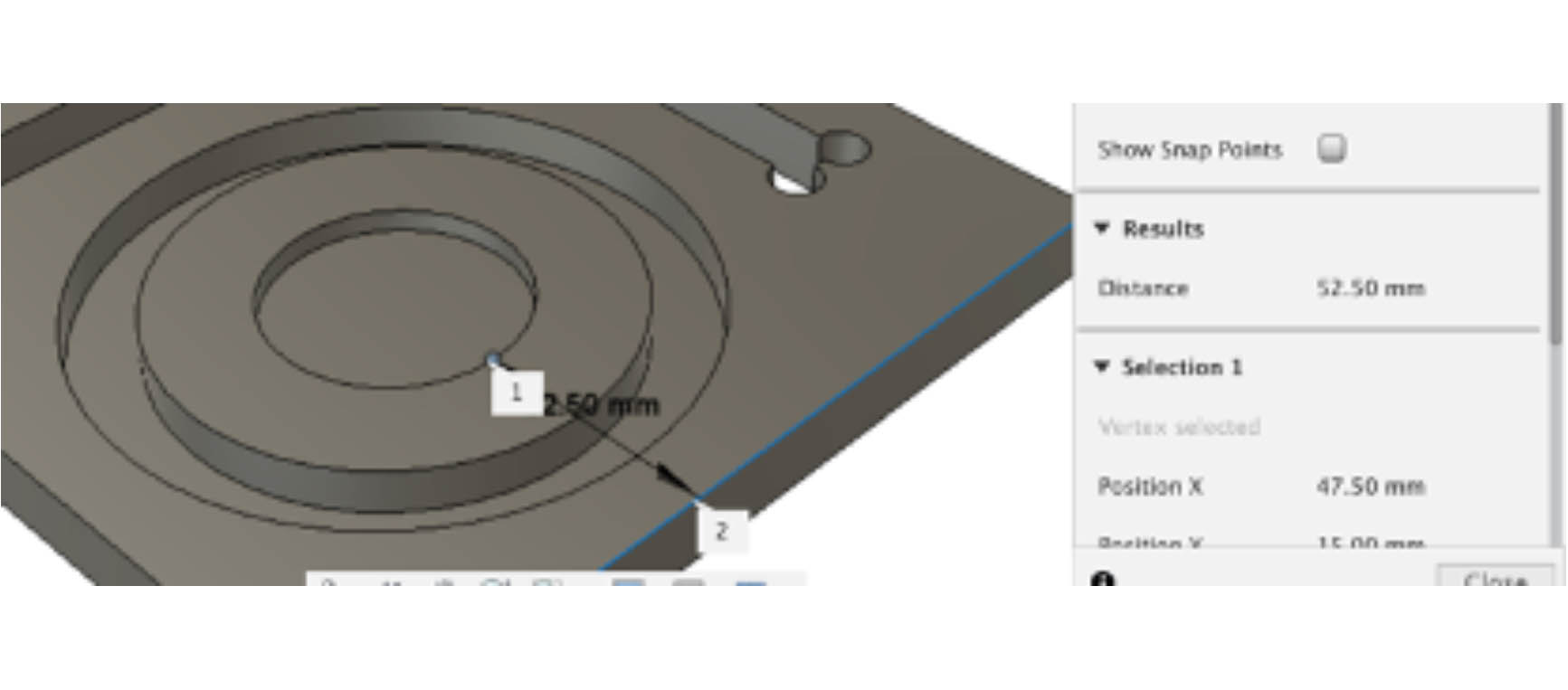
In this rectangle, the width is 10.05mm, because the depth of the cutting board is 11.00mm, and I hope the junction is tighter, so I set the depth to be 10.05mm.
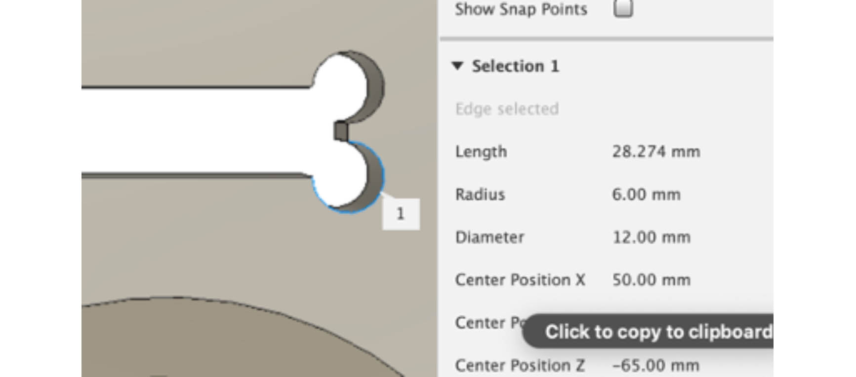
As I mentioned before, the diameter must more than 8.00mm, which is according to the milling bit. In this case, the milling bit is 8.00mm, so I set the diameter to be 12.00mm.

● Step13. Create >> line to draw the line top of the panda.
● Step14. Click the panda and the pedals and click—Create >> mirror and set up.
● Step15. Click the mirror line and right-click and choose delete.

● Step16. Create >>> Extrude and set up— select and the distance 11.00mm, because the depth of cutting board is 11.00mm.
● Step17. Create >>> Extrude and set up— select and the distance 8.00mm, because the minimum of depth of milling bit drop is 3.00mm.

Manufacture
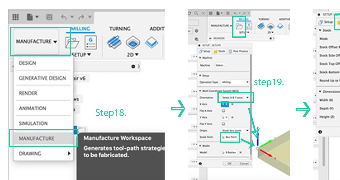
● Step18. Click Design and click manufacturer
● Step19. Click Set up >>> new set up, Next, check that the Operation Type is ‘Milling’ and set the Origin to ‘Stock box point.’ Then click on the Stock tab and change all the offset values to 0mm.
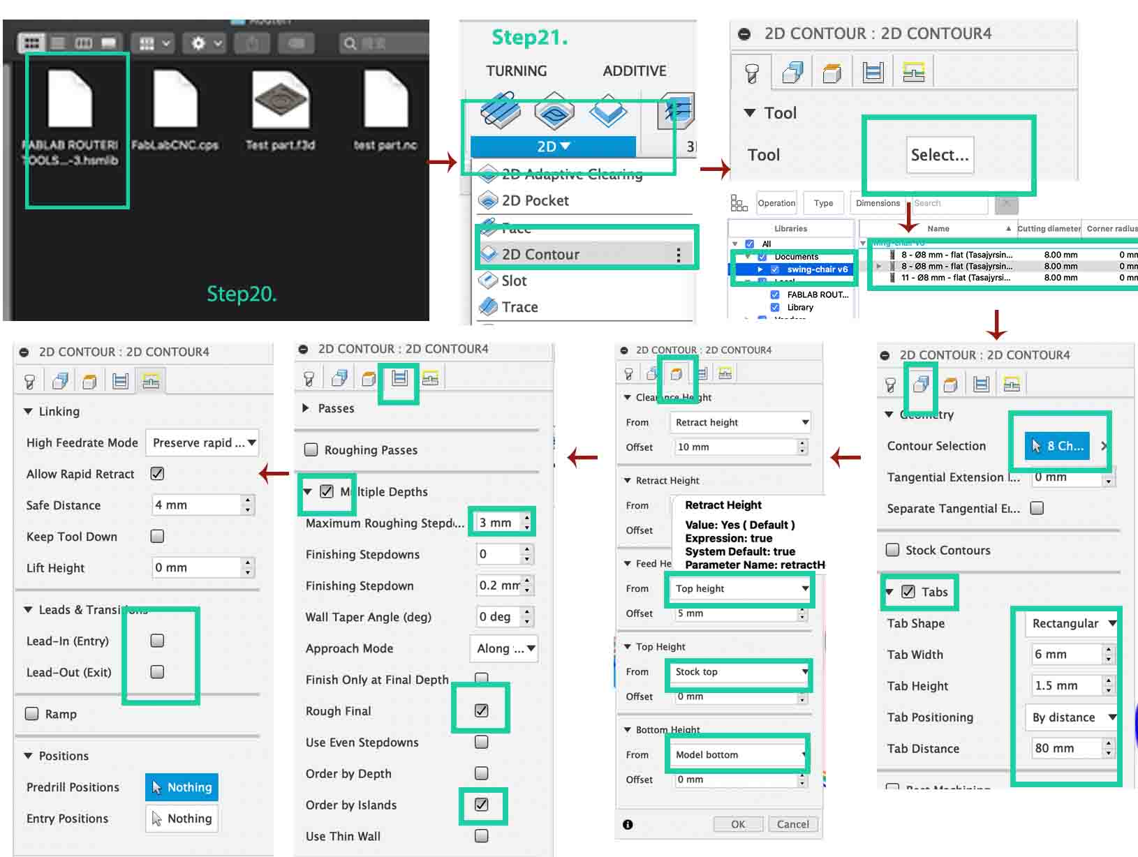
● Step20. Download the files.
● Step21. 2D >>> 2D contour and select button under the Tool tab. Then, choose the 8mm Flat milling bit from the library and set up the Geometry, Clearance height, Passes, and Linking.
● Step22. 2D >>> 2D pocket and set up (The process was more or less the same as what we did for 2D contour settings).

● Step23. 2D >>> 2D pocket and set up (The process was more or less the same as what we did for 2D contour settings).

● Step24. 2D >>> 2D pocket and set up (The process was more or less the same as what we did for 2D contour settings).

● Step25. Actions > simulation.

● Step26. Copy the FabLabCNC.cps to my laptop, and click Actions > post process.

After the first check, Eino mentioned, “Your toolpaths are wrong order - first pockets and last contours. Also (picture as an attachment) milling direction is wrong, so now it mill inside of the borderline not outside when milling red marked parts. So parts marked with red in picture will turn out smaller than their counterparts. Change that small red arrow to other direction when selecting toolpaths. Otherwise file looks ready to mill.” And attached an image.
Then, I deleted the previous 2D contour and set up the 2D contour again and change the direction of the toolpath; after that, I exported the file to replace the previous one and redo the step 25-26 and uploaded the new files.

Because of the virus, I can’t go to Fab lab to make it, so I made a demo picture, the swing panda chair should be the same as the following picture.


Milling
● Step1. Placing the milling bit. Since the milling bit, which was already installed on the machine, was a 8mm flat one, so I did not need to change the milling bit. I checked the milling bit and tighten the screws.
● Step2. Screwing the board.

● Step3. Setting the X, Y and Z origins. To accomplish that, I powered on the machine. The following figure shows the buttons on the machine. Then, I started the NcStudio software from a computer. The CNC router machine was controlled by a computer located next to the machine.
For the X and Y axes, just move the header to the desired position (be careful with the screws), and then use the W.Coord button for the X and Y in the software to set the origin. There is also an automatic calibration method for the Z axis. In this approach, I put the mobile calibrator just underneath the milling bit. Next, start the calibration process from Operation > Mobile Calibration in the software. The milling bit will move down until it touches the metal surface of the mobile calibrator, and it will automatically set the origin for the Z axis to that point.
● Step4. Opening and loading the .nc file, from File > open and load. Then, I clicked on simulation button to see if everything is OK. Next, the feedrate and Spindle values were reduced respectively to 80% and 80% of their values , in order to increase the quality of the milling process, and press the dust button. Finally, I pressed the play button to start the milling process and increase the feedrate and Spindle values to 100%.
● Step5. After milling, I found it just milled the outline, lack of the details and holes, so I open the original file, clicked the 3 pockets and clicked Action >>> post process to export the .nc file. Also, using the software from File > open and load, and simulation path.

● Step6. After milling, I cut the outline, and took it back.
Assemble
● Step1. Cleaning the edges using knife and the sandpaper.
● Step2. Assembl the chair.