Final Project
Presentation Slide
Presentation Video
I worked on defining my final project idea and started to getting used to the documentation process.
Motivation
At first, I had two thoughts that related to our daily life.
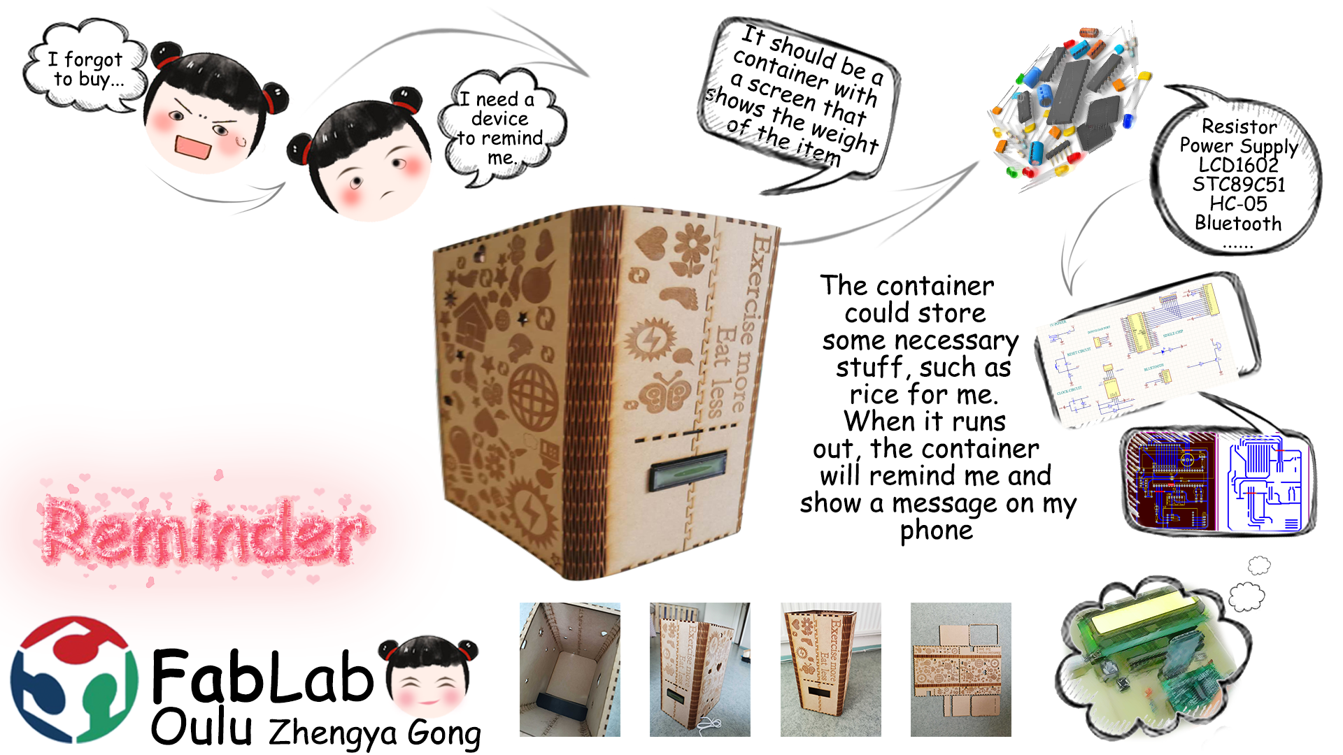
A box or container to store some necessary stuff, such as shampoo, cleansing cream, and body wash. When one of these run out, the container will remind me and show a message on my phone all day. The reason is because the last weekend when I was taking a shower preparing to wash my hair and found that the shampoo had run out. I need to go out to buy shampoo with wet hair for 10 minutes. I feel very discourage and stupid.
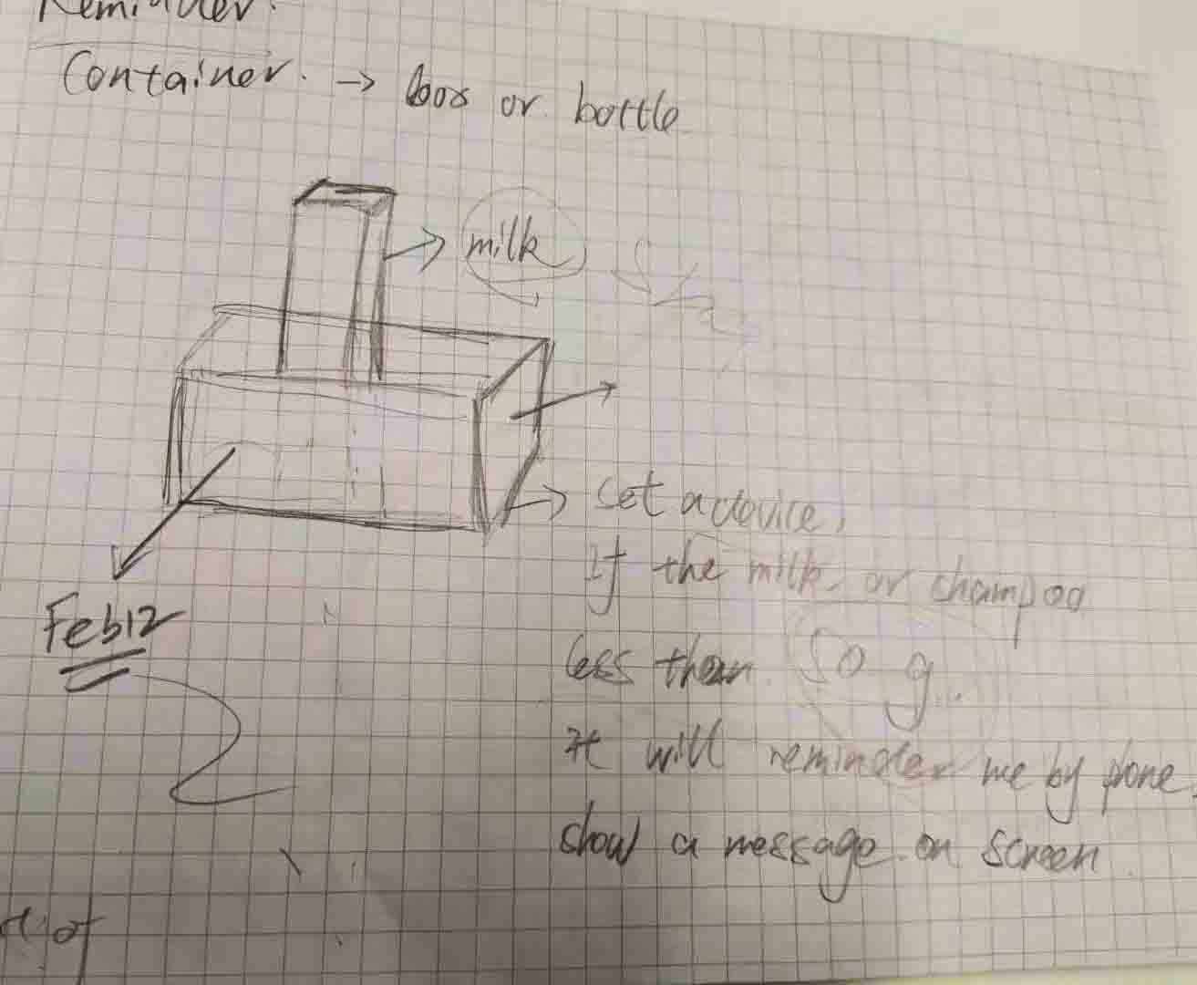
Draft 1
Slippers. This idea is also from my daily life because sometimes getting up in the morning can be a tricky thing, especially in Oulu, where it is too cold in the winter. So, I often miss the alarm clock and sleep. Therefore, I want to design the slippers that connect to the phone by Bluetooth and only turn off the alarm when it feels more than 1000 Pa of pressure. I think it could help me to get up early.
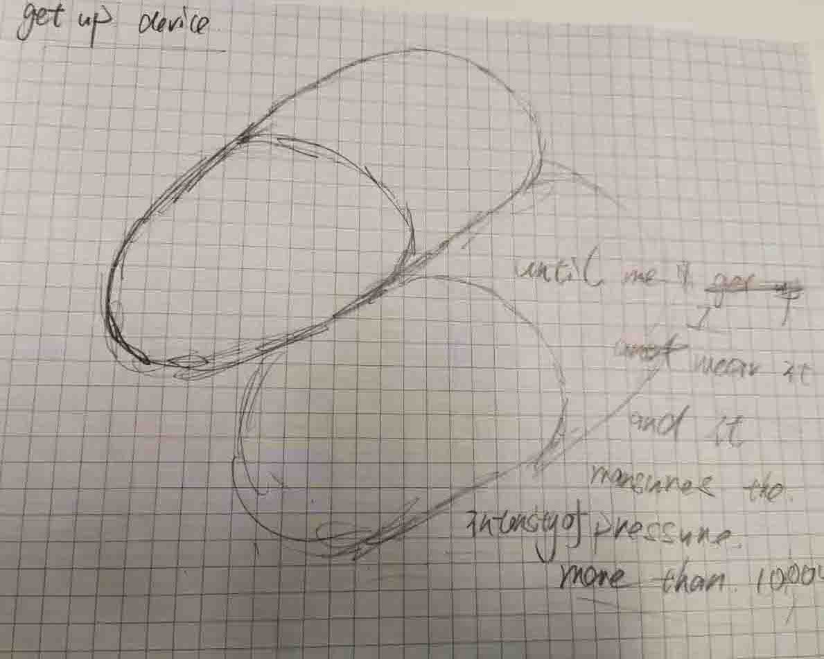
Draft 2
Finally, I decided to choose the first one after talking to my colleague Sohail and, because we think the first one is more useful than the second. Thanks to Sohail, who had been joined Fab Academy in 2017 as a student, then he was working on Fab Academy for 2 years. He helps me range the schedule and gives me many useful suggestions.
2D and 3D Modeling
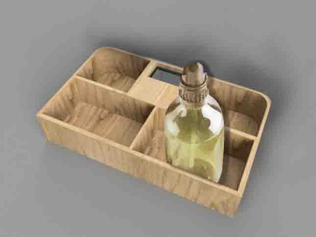
The container will be divided into 5 separated blanks, 4 for necessary stuff, and 1 for battery and screen.
2D model
3D model
Questions and answers
What will it do?
● A box or container to store some necessary stuff, such as rice. When it runs out, the container will remind me and show a message on my phone. The reason is because the last weekend when I was hungry, I found that the rice had run out. I need to go out to buy it. I feel very discourage and stupid, so I wonder can I design something to store the rice, when it almost runs out, it will remind me.
Who’s done what beforehand?
● Some final projects from Fab Academy that are related work:
Weight scaleThe site shows how the weight sensor work.
E-binThis final project shown the frame of the box.
According to these projects, that inspired me a lot. Because of the first one, I choose the same weight sensor and using a similar frame box as the second project.
What will you design?
● The 2D design and cut it using a laser cutter for the frame of the case.
● The 3D design and print it using a 3D print machine to make the internal case to protect the electronics.
● I will do the electronics design, just one PCB board, connected sensor and output devices, for example, input the weight sensor, output the alarm, LCD1602, and LED, then manufacturing and programming.
What materials and components will be used? Where will parts come from? And how much will they cost?
Most of components for electronics design from China, I know I can take it from Fab Lab, while I prepared the final project early when the virus was spreading, the Fab Lab was closed. Also, because I am not good at electronics design, so I discussed with my friends to consult which methods, software, and components I should use? He helps me a lot, and I brought the components from China, it is cheaper than from Amazon and other online shops.
Also, I need to use the Laser cutter and 3D print machine for my final project, so I need to use the PLA material for 3D printing and MDF for Laser cutting.
How much will they cost?
Electronics:
| Description | Price | Pcs | Total |
|---|---|---|---|
| LED | 0.135 € | 1 | 0.135 € |
| Resistor | 0.10 € | 5 | 0.50 € |
| STC89c5-microcontroller with casing | 0.84 € | 1 | 0.84 € |
| 11.0592 MHZ Crystal Oscillator | 0.22 € | 2 | 0.22 € |
| HX711 Weighing Sensor Module | 0.54 € | 1 | 0.54 € |
| DuPont Cable 4 pin | 0.02 € | 1 | 0.02 € |
| PCB tactile switch 6mm 500x500 | 0.03 € | 1 | 0.03 € |
| Push Button Switch PCB 8x8mm | 0.39 € | 1 | 0.39 € |
| Ceramic 30 | 0.01 € | 2 | 0.02 € |
| TMB12A05 5V DC piezo buzzer | 0.06 € | 1 | 0.06 € |
| LCD 1602 with casing | 0.20 € | 1 | 0.20 € |
| Bluetooth HC-5 | 3.20 € | 1 | 3.20 € |
| Resisters Packs | 0.10 € | 1 | 0.10 € |
| S8550 Transistor | 0.50 € | 1 | 0.50 € |
| USB Power cable DC5V | 0.60 € | 1 | 0.60 € |
| DC-005 3Pin Black DC Power | 0.05 € | 1 | 0.05 € |
| Male Female Dupont Wire Jumper | 0.01 € | 1 | 0.01 € |
| total | 7.086 € |
I brought most components in Taobao except the LED, Resistor that from our Fablab.
Other:
| Description | Price | Pcs | Total |
|---|---|---|---|
| MDF | 1.50 € | 1 | 0.15 € |
| PLA | 2.00 € | 1 | 2.00 € |
| total | 3.15 € |
The material from out Fablab.
What parts and systems will be made?
● An external case to place objects
● An 3D printed internal case to protect pcb board
● A support plate between the weight sensor and objects A partition for protecting electronic equipment: 3D design and 3D print machine:
● A PCB containing the load cell and the bluetooth module to send data to the mobile phone
● A mobile phone app that will read the data sent from the PCB.
What processes will be used?
● PCB design
● 2D design
● 3D design
● Computer controlled cutting using a laser cutter
● Computer controlled cutting using a 3D print machine
● Embedded programming
● Board Milling and Soldering
● Mobile Devices Application Design
What questions need to be answered?
● How to code programming required for this project?
● What additional sensors do I need?
● What UI to be used to display the values on a smartphone?
How will it be evaluated?
● The weight sensor can measure the weight.
● The LCD1602 can show the weight.
● When the weight sensor measure the weight less than 100g, the buzzer beep few seconds.
● By the bluetooth, my phone will receive the item weight, and when the weight is less than 100g, it will remind me. I can stop the alarm by press the button.
Electronic design
Preparation: Download and read components data sheet.
By reading the data sheet, I learned that so many information about the product is included in Data Sheet. There is really a lot of information in the data sheet. Too much for a beginner like me to actually get into unless I know what I’m looking for. The pinout is very important.
● HX711 Balance Module With Load Cell data sheet
This module uses 24 bit high-precision A / D converter. This chip is designed for high-precision electronic scale and design, has two analog input channels, programmable gain of 128 integrated amplifier. The input circuit can be configured to provide a bridge voltage electrical bridge (such as pressure, load) sensor model is an ideal high-precision, low-cost sampling front-end module.
HX711 Pin Description
Load Cell Wire Connection
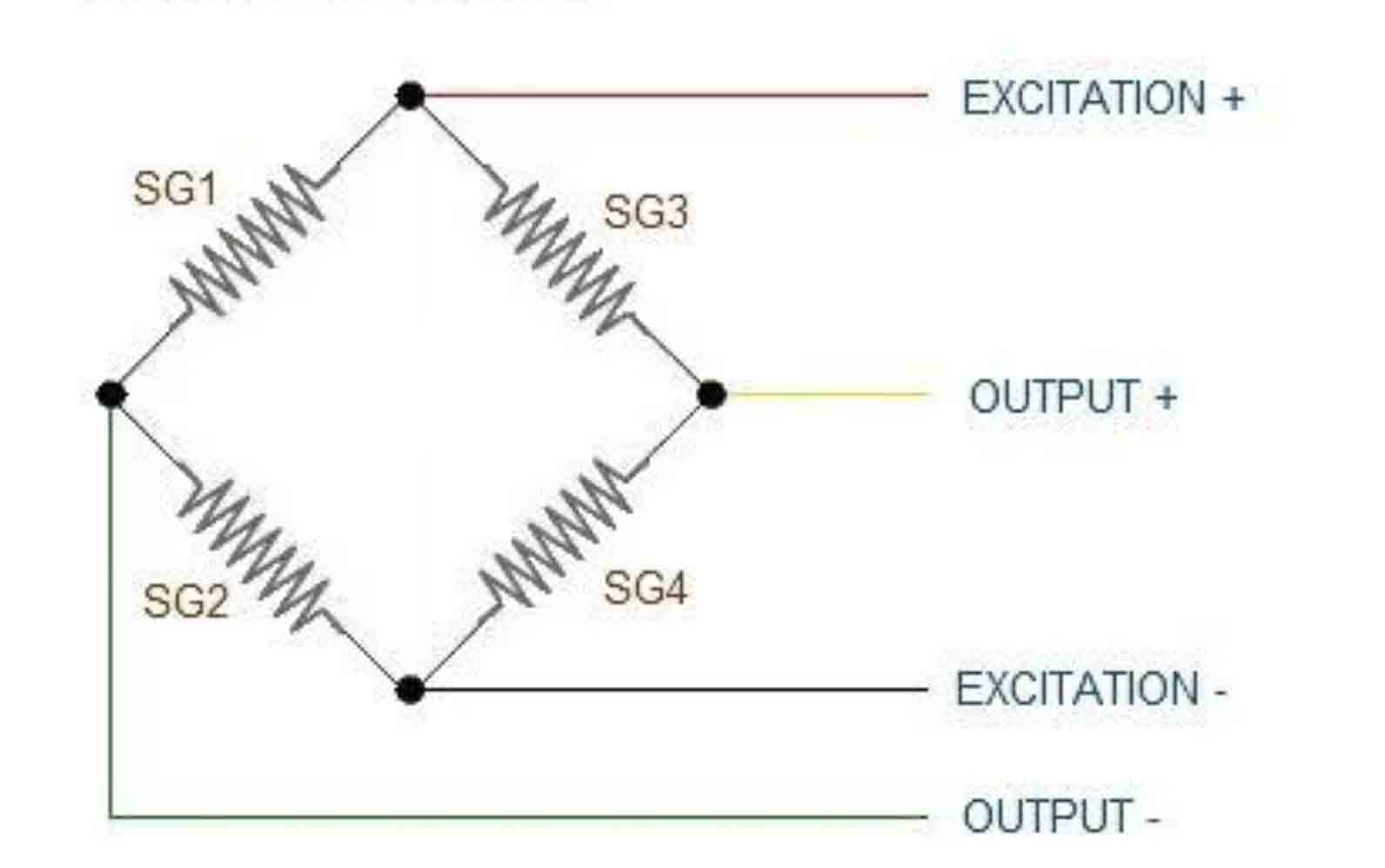
Load Cell to HX711
E+ : WHITE
E- : BLACK
A- : RED
A+ : GREEN
HX711 to STC89C52
GND:GND
VCC:VCC
SCK:P13
DT:P12
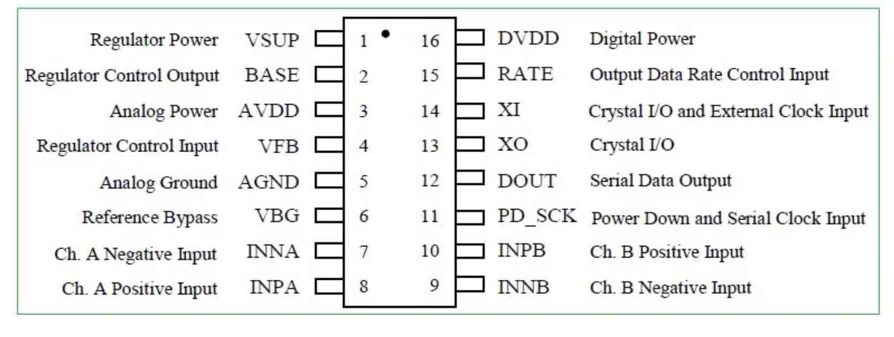
STC89C52 is fully compatible to the standard 8051 microcontroller, maintains all instruction mnemonics and binary compatibility. STC89C52 can execute the fastest instructions per 6 clock cycles or 12 clock cycles(as the same as the standard 80C51) . Improvement of individual programs depends on the actual instructions used.
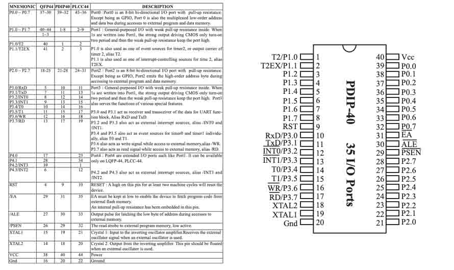
Pin description of STC89C52
-
- Main power pin VCC and VSS
The power supply VCC is connected to +5V, and the VSS ground terminal is the public reference ground
-
- Clock circuit pins XTAL1 and XTAL2
STC89C52 chip is equipped with an inverter amplifier, and XTAL1 is the input terminal of the amplifier. XTAL2 is the output end of the amplifier and the input end of the internal clock generator. When using the self-excited oscillation mode, XTAL1 and XTAL2 are externally connected with quartz crystal oscillator, and the internal oscillator oscillates according to the crystal oscillator frequency to generate clock signal.
-
- Control signal pin
-(1)RST – reset input. When the oscillator is working, the RST pin with a high level of more than two machine cycles will be the MCU reset.
-(2)ALE/PROG – when accessing external program memory or data memory, ALE(address latches allow) outputs pulses of the lower 8-bit bytes used to lock the address. In general, ALE still outputs a fixed pulse at 1/6 of the clock oscillation frequency, so it can output a clock or be used for timing purposes. Note that a ALE pulse is skipped each time the external data store is accessed. (generally not used)
-(3)PSEN – program storage allowed (PSEN) output is the read selected communication number of external program memory. When STC89C52 fetches instructions (or data) from external program memory, each machine cycles PSEN twice, that is, outputs two pulses. During this period, when accessing external data memory, PSEN signals will be skipped twice.
-(4)EA/VPP – external access allowed. To enable the CPU to access only external program memory (address 0000h-ffffh), the EA terminal must remain low (grounded). Note that if the encryption bit LB1 is programmed, the state of the EA end will be locked internally during reset. If the EA end is at a high level (connected to the Vcc end), the CPU executes instructions from the internal program memory. When programming FLASH memory, the pin plus +12V programming allows the power supply Vpp, of course it must be that the device is using 12V programming voltage Vpp.
-(5) parallel I/O port P0~P3 terminal pins
P0 port (P0.0~P0.7) 8-bit drain switch type bidirectional I/O port. It can be used as a universal I/O port, but must have a pull resistance.
P1 port (P1.0~P1.7) is an 8-bit quasi-bidirectional I/O port with pull resistance.
Port P2 (P2.0~P2.7) is an 8-bit quasi-bidirectional I/O port with pull resistance.
P3 port (P3.0~P3.7) is an 8-bit bidirectional I/O port with pull resistance.
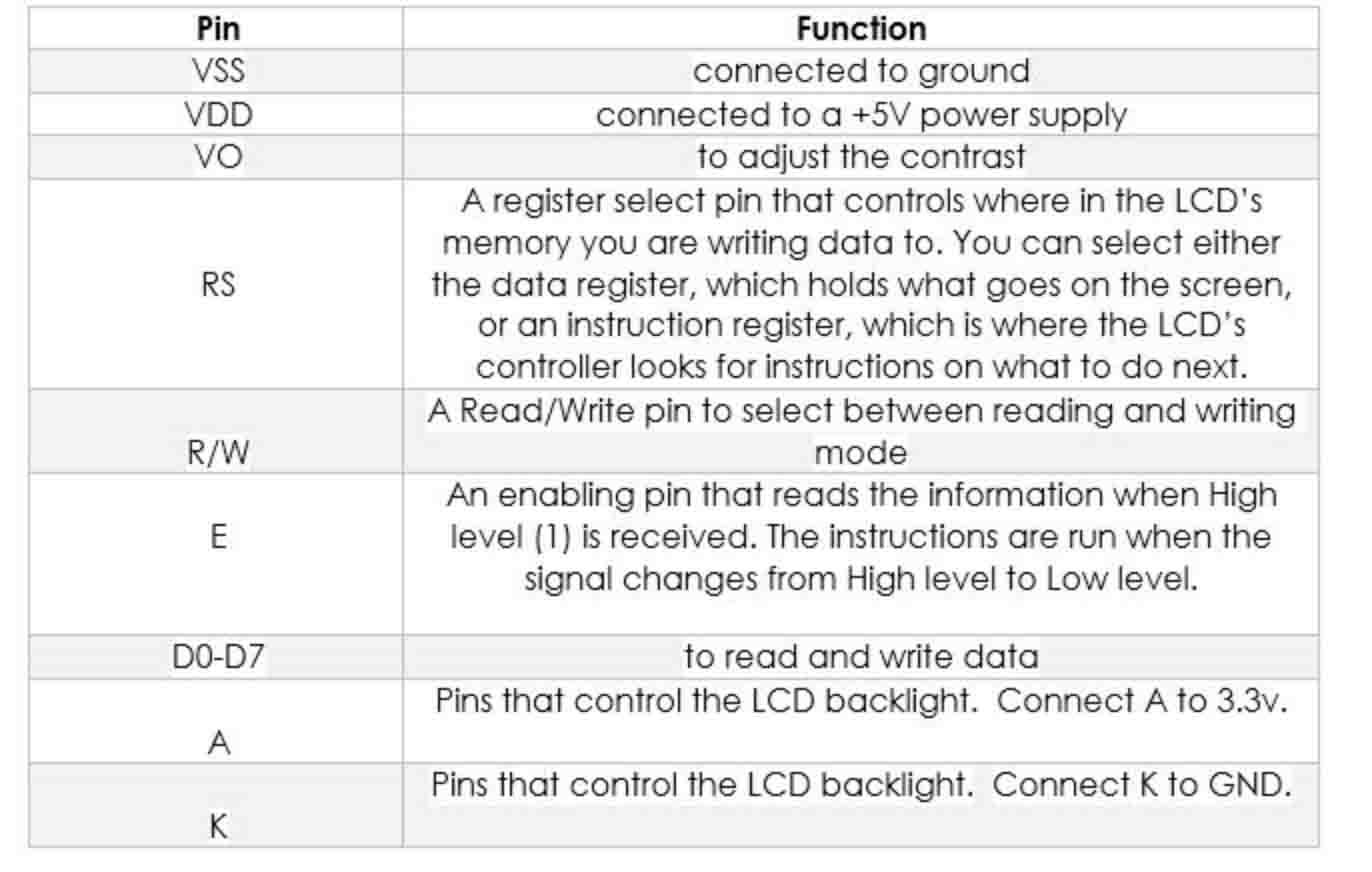
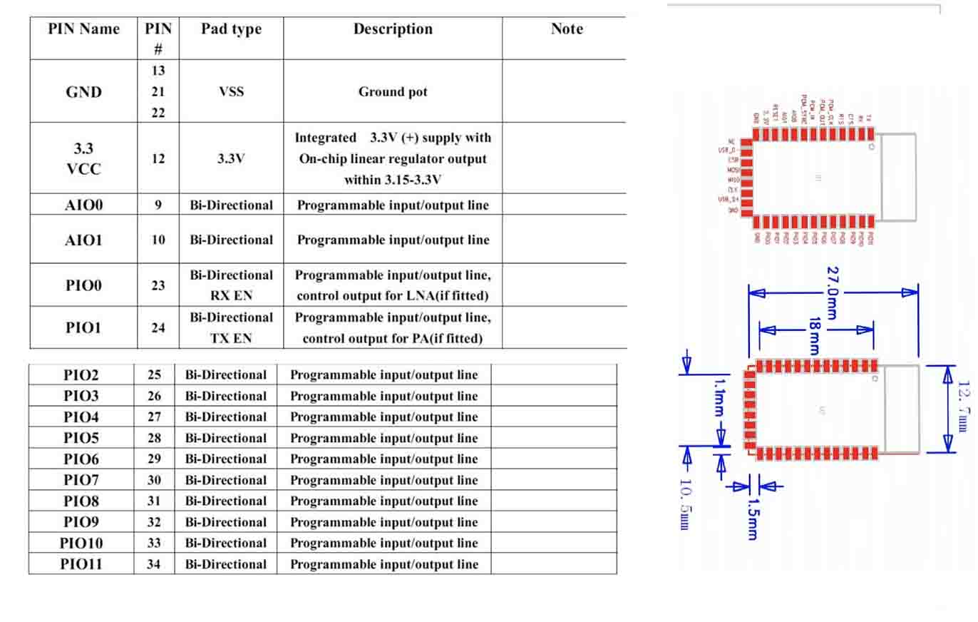
LCD1602, or 1602 character-type liquid crystal display, is a kind of dot matrix module to show letters, numbers, and characters and so on. It’s composed of 5x7 or 5x11 dot matrix positions; each position can display one character. There’s a dot pitch between two characters and a space between lines, thus separating characters and lines. The model 1602 means it displays 2 lines of 16 characters. Generally, LCD1602 has parallel ports, that is, it would control several pins at the same time. LCD1602 can be categorized into eight-port and four-port connections. If the eight-port connection is used, then all the digital ports of the SunFounder Uno board are almost completely occupied.
The pins description
HC-05 module is an easy to use Bluetooth SPP (Serial Port Protocol) module, designed for transparent wireless serial connection setup. Serial port Bluetooth module is fully qualified Bluetooth V2.0+EDR (Enhanced Data Rate) 3Mbps Modulation with complete 2.4GHz radio transceiver and baseband. It uses CSR Bluecore 04-External single chip Bluetooth system with CMOS technology and with AFH(Adaptive Frequency Hopping Feature). It has the footprint as small as 12.7mmx27mm.
The pin description and Hardware
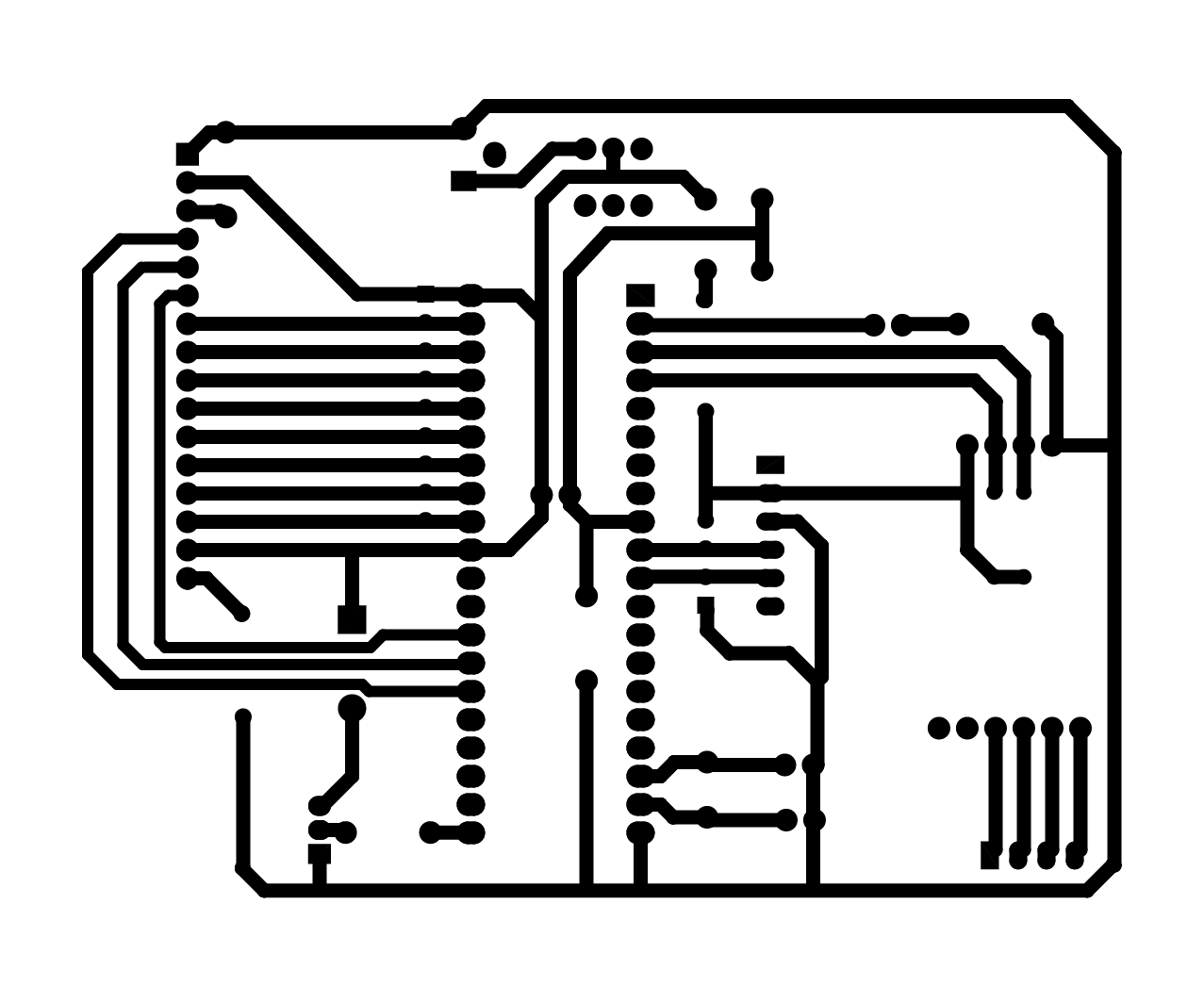
Board design
I am interesting in the electronic design, so I learned another software Altium designer, also used it to design my PCB board.
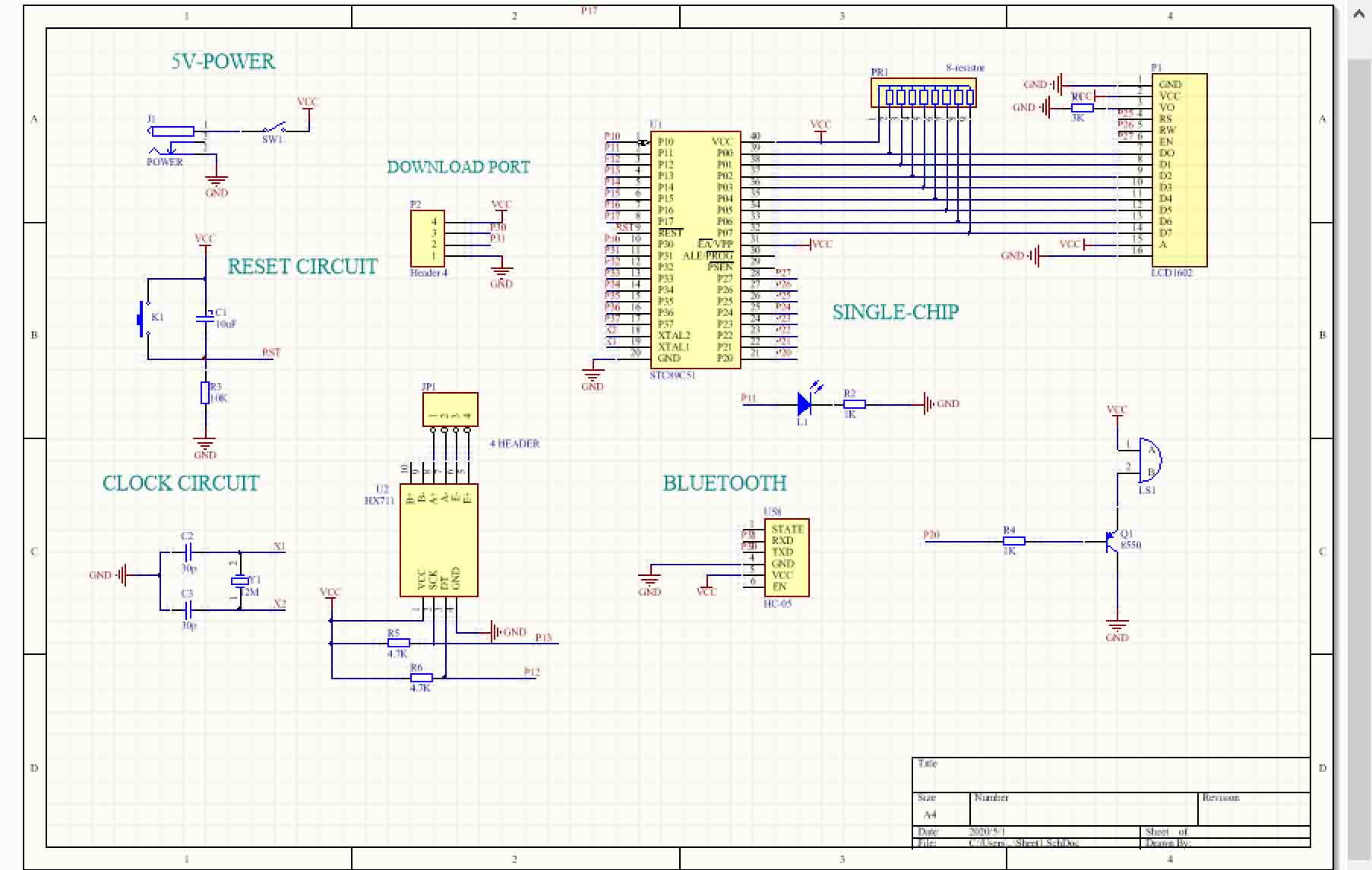
● 1. Design the Schematic. I downloaded the library, created the new project, and created the new Schematic. Then put the components and using the line tool to connect it.
● 2. Design the PCB board. In this stage, it is a bit of different, it should create the new PCB and selected the design >> update PCB Document.
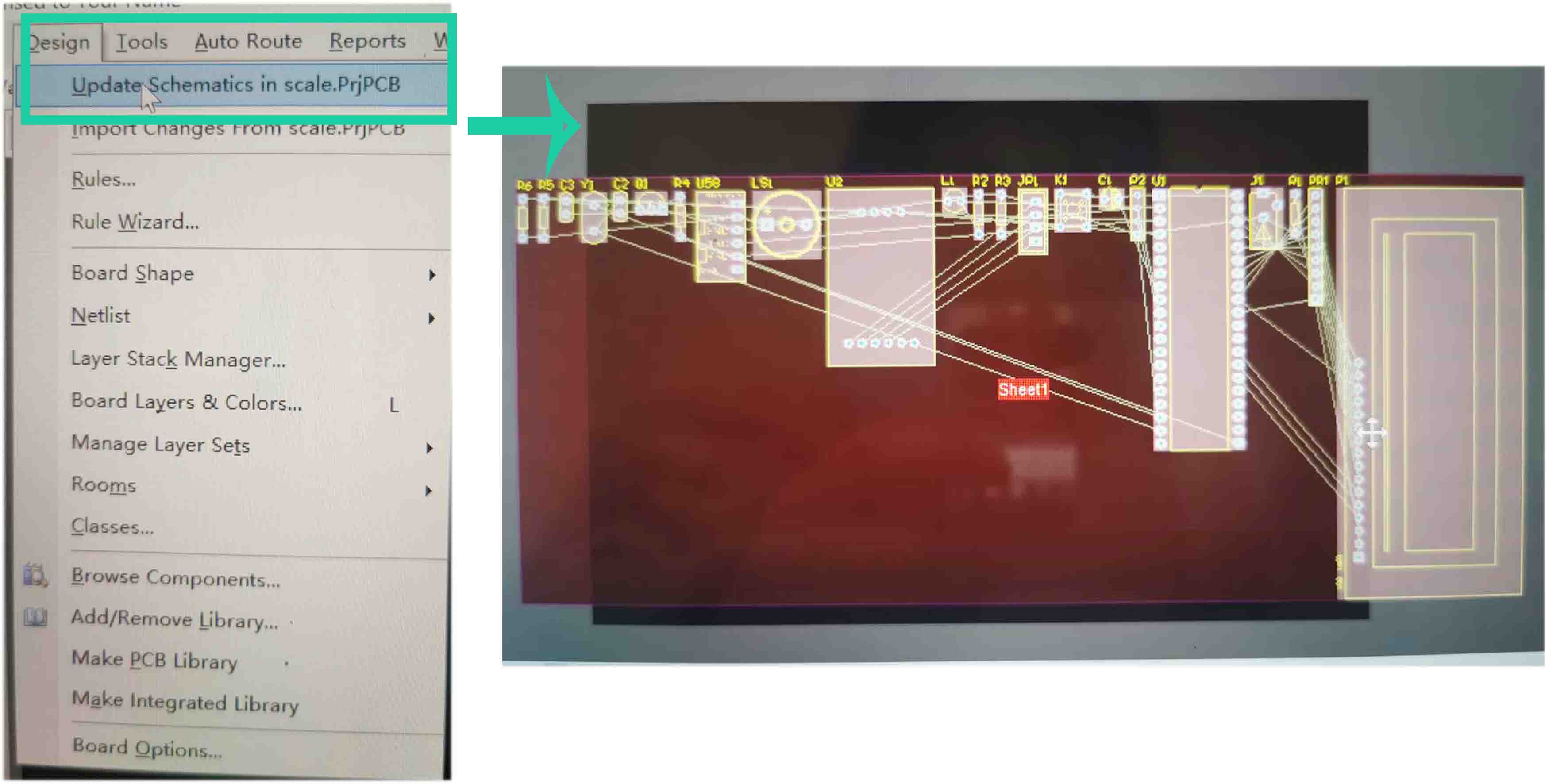
Then using Move to put the components and using line to connect the pins. Also I set the line to be 50 mil, the clearance to be 10 mil.
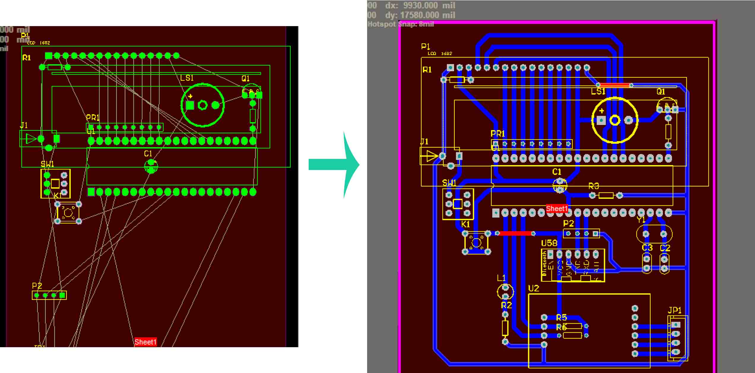
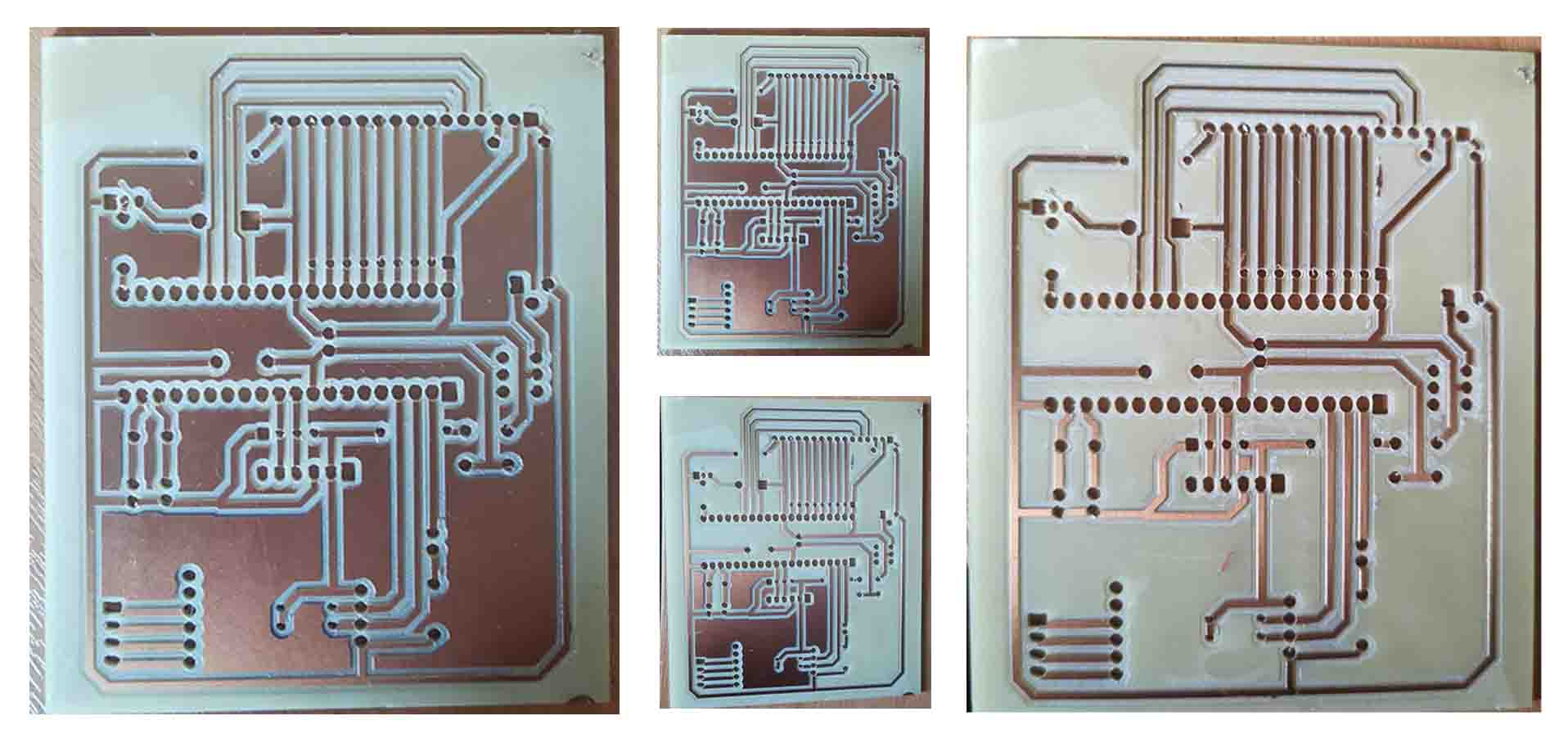
● 3. When I done the design work, I save it as DWG. Also, the lines shown different color according to the color of layers.
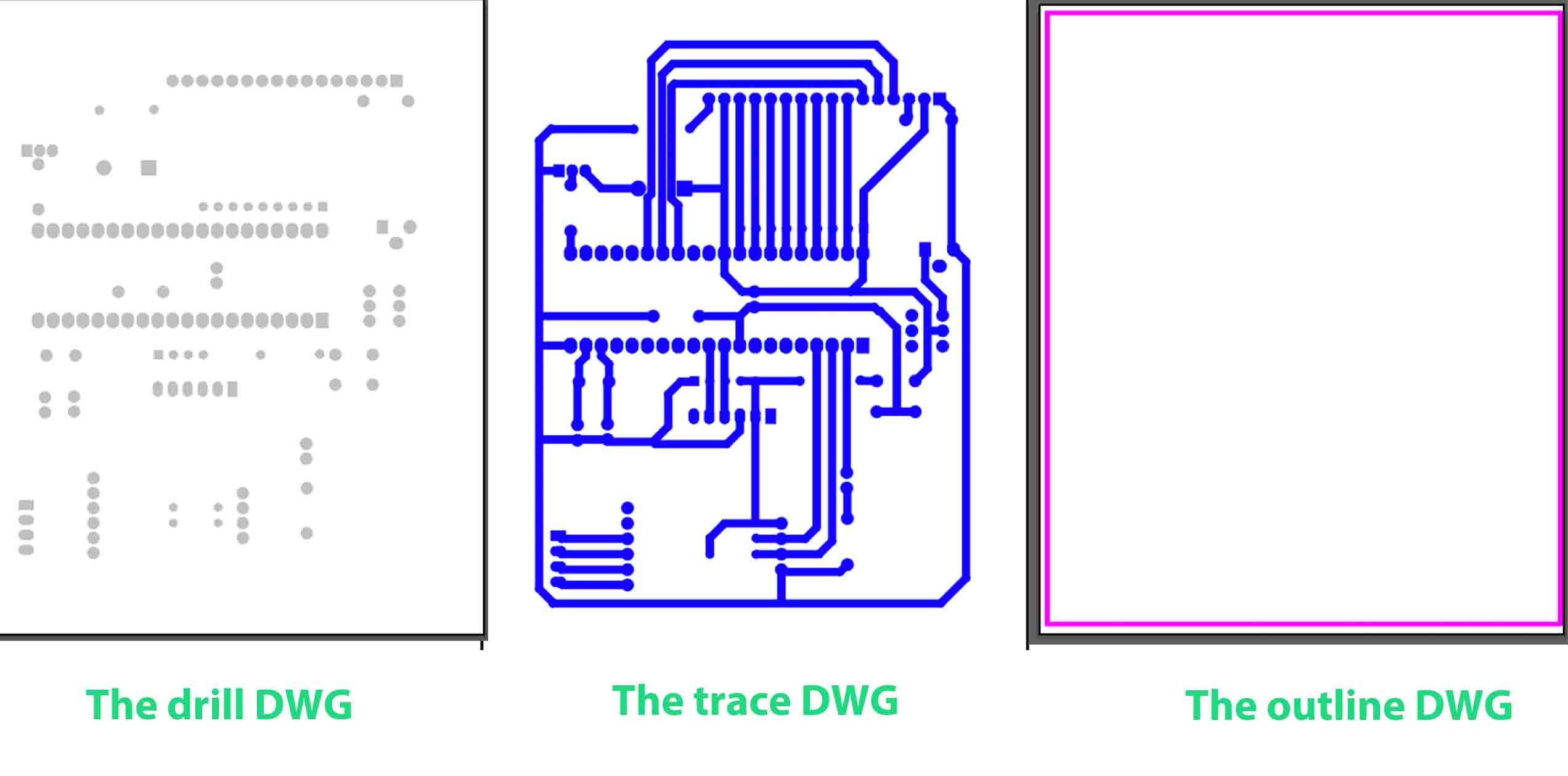
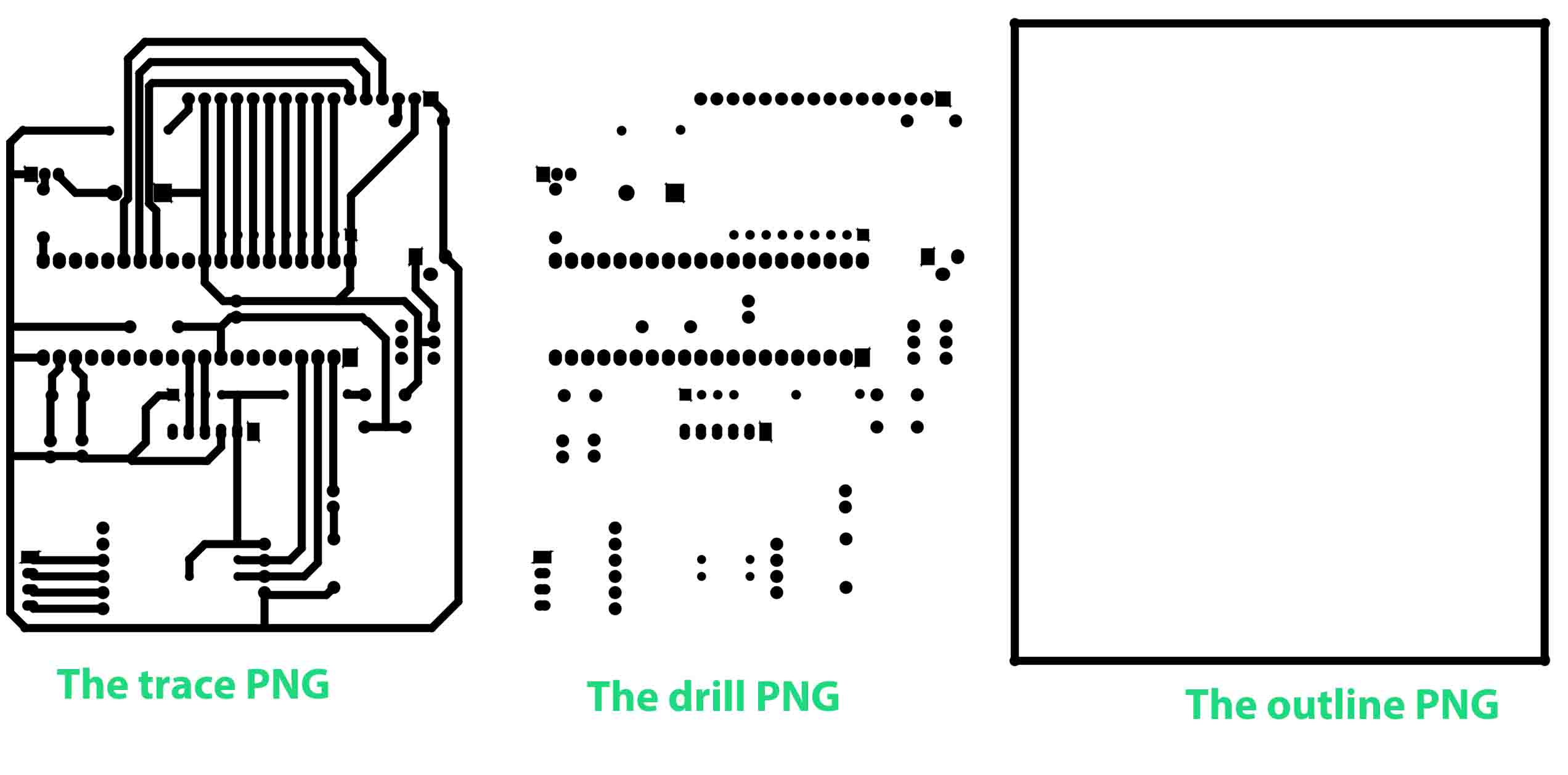
● 4. I opened the files using Adobe Illustrator, and changed the color to be black, then mirror and save it to be PNG files.
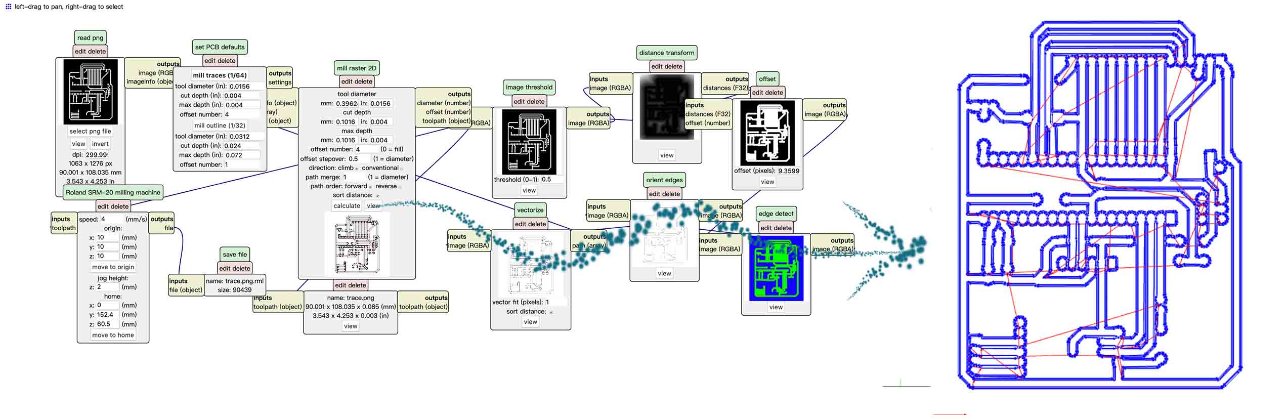
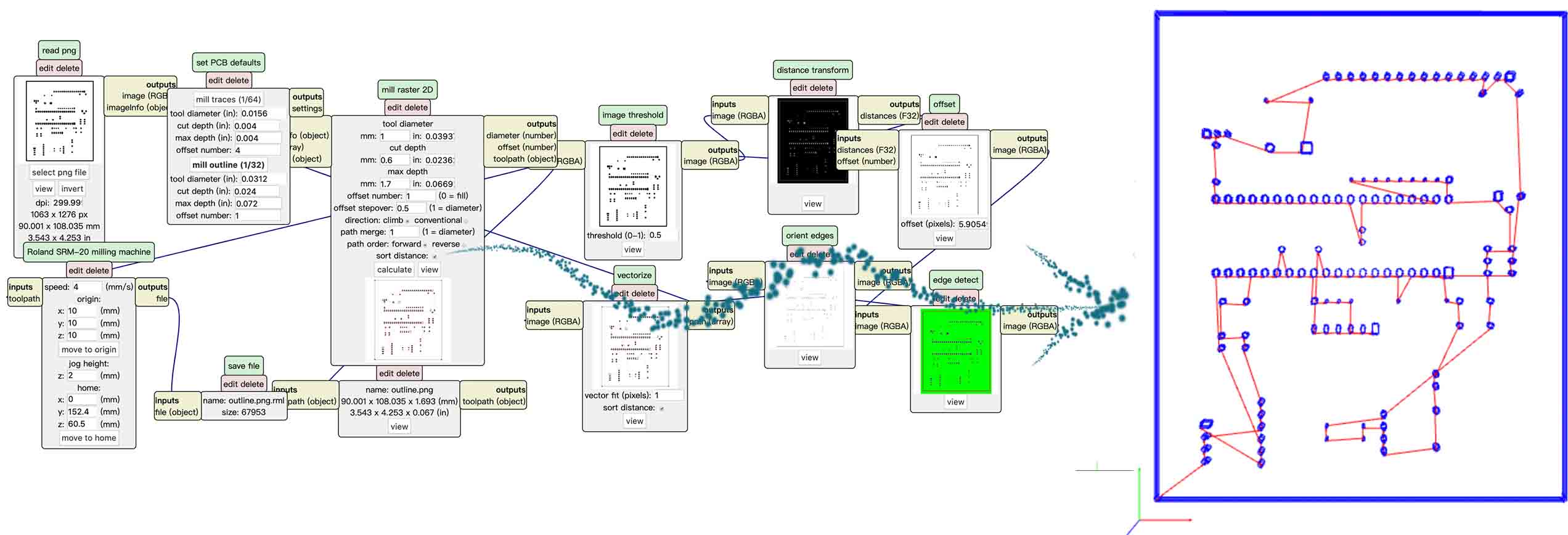
● 5. Open mods, and set it as the 4 weekly assignmentand 6 weekly assignment. Then the rml files created and downloaded automatically.
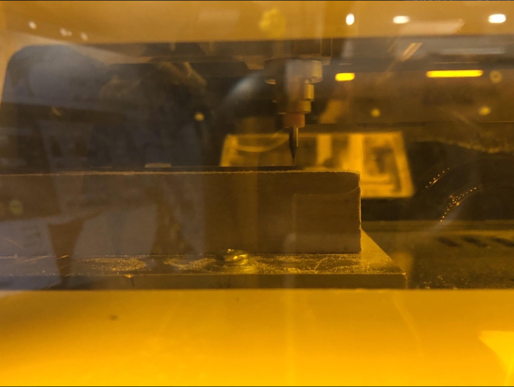
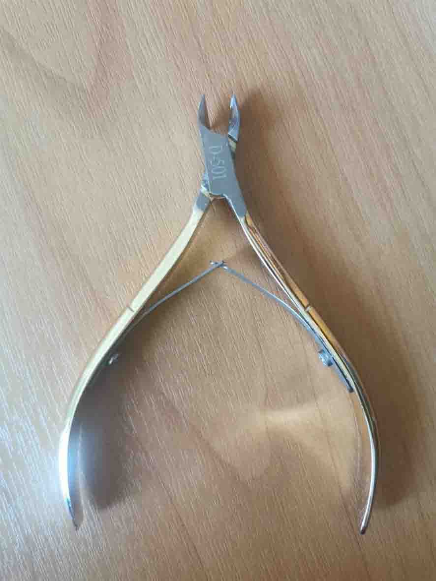
● 6. After milling the PCB board, I would like to make the Lines clear, so that I can soldering it better. I tore off the excess metal layer using a special nail clippers.
● 7. I borrowed a soldering gun from a friend and start to soldering my PCB board according the PCB file at home. Unfortunately, I forgot to soldering other board that broken last month before I return it.
Programming
It is a challenge for me. I used the Keil (download link)to write the code and STC-ISP (download link to program. The reason because the Keil is easy for new one to program, and many people recommended to use it. The another reason because I found various codes related to my project online. I downloaded the codes and edited it.
write the code
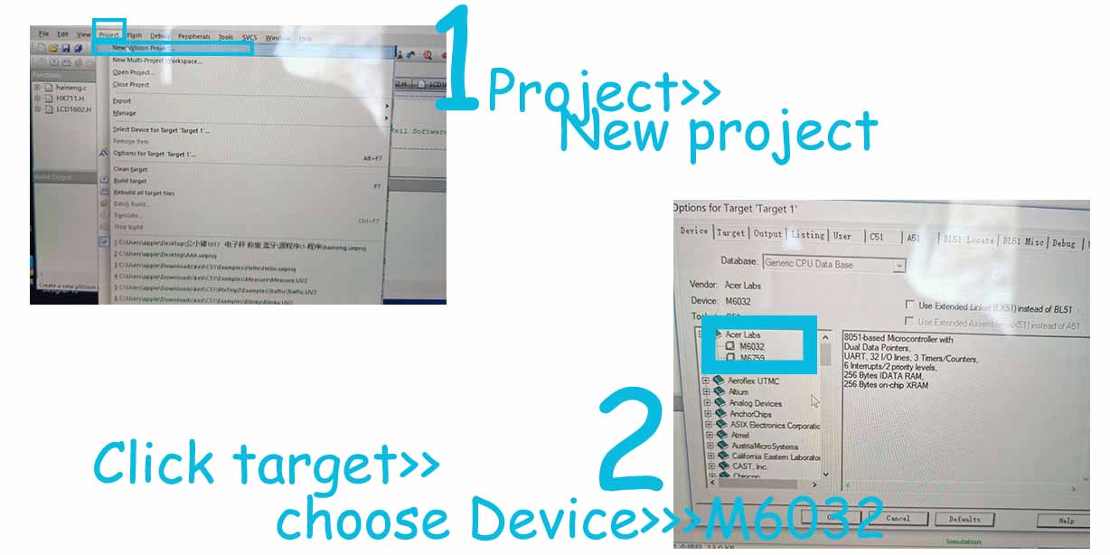
● 1. Download the Keil (download link), and create a new project.
● 2. Choose the target, then click the device to choose M6032.
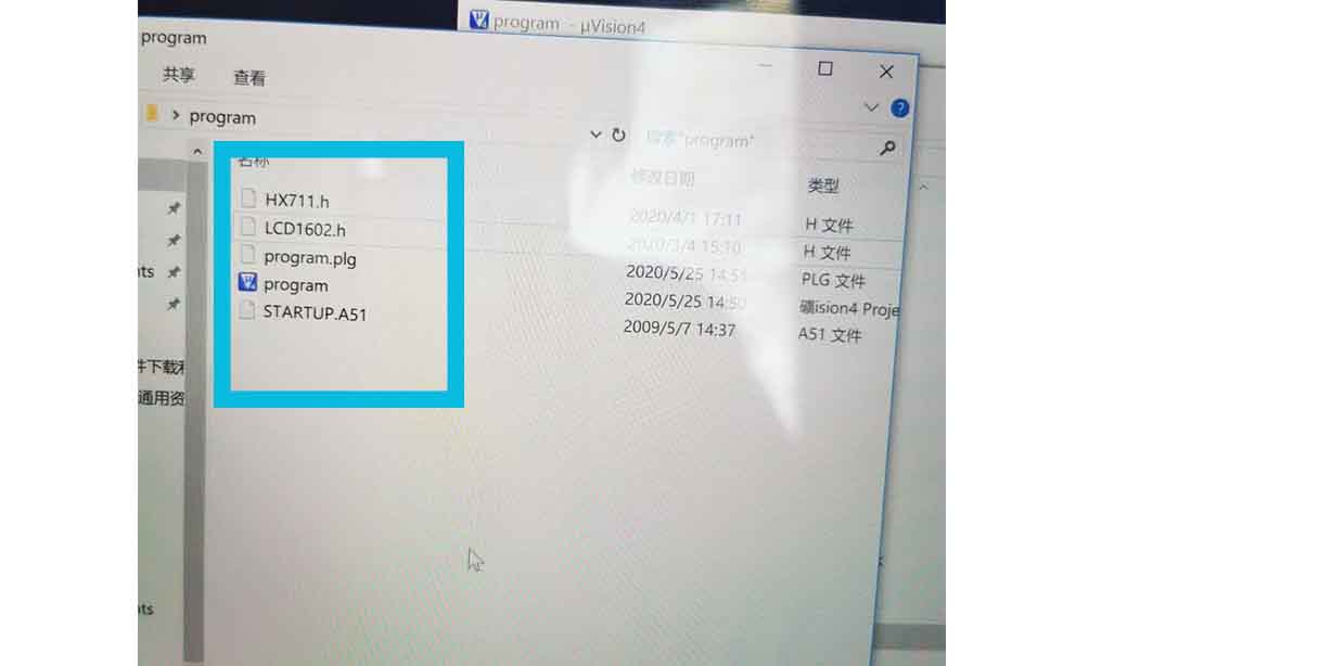
● 3. Store the project in a folder, it will automatically create another files, named .plg and startedup.A51 and added the HXL711.h and LEC1602.h. in the folder.
● 4.Write program in C using Keil.
I just copied some code from open source1, and according my project to edit it.
To control the weight sensor using HX711, code from forums1 and forums2.
#ifndef __HX711_H__
#define __HX711_H__

#include <intrins.h>
#include <string.h>


unsigned long HX711_Buffer = 0;
unsigned long Weight_Maopi = 50;
 unsigned long Weight_Maopi_0 = 0;
 unsigned long Weight_Shiji = 0;
 unsigned long  Weight_Shiwu = 0;

#define GapValue 379

//=================================//IO set

sbit HX711_DOUT=P1^2;
sbit HX711_SCK=P1^3;

//Function or variable declarations
extern void Delay__hx711_us(void);
extern unsigned long HX711_Read(void);


//****************************************************
//The time delay function
//****************************************************
void Delay__hx711_us(void)
{
    _nop_();
    _nop_();
}

//****************************************************
//Read HX711
//****************************************************
unsigned long HX711_Read(void)
{
    unsigned long count;
    unsigned char i;
    HX711_DOUT=1;
    Delay__hx711_us();
    HX711_SCK=0;
    count=0;
    while(HX711_DOUT);
    for(i=0;i<24;i++)
    {
        HX711_SCK=1;
        count=count<<1;
        HX711_SCK=0;
        if(HX711_DOUT)
            count++;
    }
    HX711_SCK=1;
    count=count^0x800000;//When the 25th pulse comes down the edge, convert the data
    Delay__hx711_us();
    HX711_SCK=0;
    return(count);
}


//****************************************************
//MS delay function (test under 12M crystal vibration)
//****************************************************
void Delay_ms(unsigned int n)
{
    unsigned int  i,j;
    for(i=0;i<n;i++)
        for(j=0;j<123;j++);
}


//****************************************************
//Measuring weight
//****************************************************
uint jilu;
uint zhongliangcha;
void Get_Weight()
{
    static  bit maopi=1;
    Weight_Maopi_0  = HX711_Read()/GapValue;
    Weight_Maopi_0 = Weight_Maopi_0%10000;

    if(maopi)
    {


                if(Weight_Maopi_0==Weight_Maopi)
                maopi=0;
                Delay_ms(200);
                Weight_Maopi = Weight_Maopi_0  ;
    }else
    {
        Weight_Shiji = Weight_Maopi_0 - Weight_Maopi;       //get net weight
//              Weight_Shiwu = Weight_Shiji; //ce shi yong
        if(Weight_Shiji>5&&Weight_Shiji<90000 )
        {


                if(Weight_Shiji%10==0)
                {
                        Weight_Shiwu =  Weight_Shiji  ;
                }
                else
To control the LCD1602 Screen, the code
#ifndef _LCD1602_H_
#define _LCD1602_H_

#define uchar unsigned char
#define uint unsigned int

#define LCD1602_dat P0  //Data parallel port macro definition


sbit LCD1602_rs=P2^5;//IO definition
sbit LCD1602_rw=P2^6;
sbit LCD1602_e=P2^7;


void LCD1602_delay(uint T) //The time delay function
{
    while(T--);
}

/********************************************************************
* name: LCD1602_write(uchar order,dat)
* function: 1602 write as data function
* input: order is the data/command switch variable //0 is the command 1 is the data
* : dat is the data/command sending data
* output: none
***********************************************************************/
void LCD1602_write(uchar order,dat)  //1602 One byte processing
{
    LCD1602_e=0;
    LCD1602_rs=order;
    LCD1602_dat=dat;
    LCD1602_rw=0;
    LCD1602_e=1;
    LCD1602_delay(1);
    LCD1602_e=0;
}
/********************************************************************
* name: LCD1602_writebye(uchar *prointer)
* function: 1602 write data function pointer
* input: enter what needs to be displayed
* output: none
***********************************************************************/
void LCD1602_writebyte(uchar *prointer)  //1602 String processing
{
    while(*prointer!='\0')
    {
        LCD1602_write(1,*prointer);
        prointer++;
    }
}
/********************************************************************
* name: LCD1602_cls()
* function: initialize 1602 liquid crystal
* input: none
* output: none
***********************************************************************/
void LCD1602_cls() //1602 initialization
{
    LCD1602_write(0,0x01);     //1602 clearing instructions
    LCD1602_delay(1500);
    LCD1602_write(0,0x38);     // Function Settings: 8-bit, 5*7 lattice
    LCD1602_delay(1500);
    LCD1602_write(0,0x0c);     //Set the cursor not to show the switch, not to show the cursor, the character does not flicker
    LCD1602_write(0,0x06);
    LCD1602_write(0,0xd0);
    LCD1602_delay(1500);
}
● 4. Write the codes, that included the HXL711.h and LEC1602.h.
Actually, I downloaded the codes online and edited, the main different is following.
#include <reg52.h>
#include"LCD1602.h" //LCD1602 display
#include"HX711.h"//read weight
#define uchar unsigned char
#define uint unsigned int
//---------------------------------->T0
bit read_Weight=0;//Read the weight marker bit
sbit Led=P1^1;
sbit beep=P2^0;
//----------------------------------->Function declaration
void display();//display function
void T0init();//T0 initialization
void AnJian();// key
void uart_zijie(uchar zijie);
void uart_zifu(uchar *zifu);
//********Main function *****************************
void main()
{
T0init();//T0 initialization
LCD1602_cls(); //LCD1602 initialization
//==========major cycle==============================
while(1)
{
display();
if(read_Weight)
{
read_Weight=0;
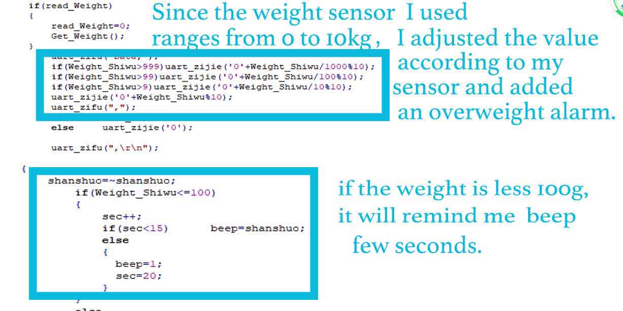
Get_Weight(); //As the variable Weight_Shiwu is generally 10 kilograms, an overweight alarm should be added }
uart_zifu("Data,");
if(Weight_Shiwu>999)uart_zijie('0'+Weight_Shiwu/1000%10);
if(Weight_Shiwu>99)uart_zijie('0'+Weight_Shiwu/100%10);
if(Weight_Shiwu>9)uart_zijie('0'+Weight_Shiwu/10%10);
uart_zijie('0'+Weight_Shiwu%10);
uart_zifu(",");
if(Led) uart_zijie('1');
else uart_zijie('0');
uart_zifu(",\r\n");
}
}
//========T0 initialization==========================
void T0init()//T0 initialization
{
TMOD=0x01;
TL0 = 0x00; //Set the initial timing value of 50ms
TH0 = 0x4C; //Set the timing initial value
ET0=1;
TR0=1;
EA=1;
SCON = 0X50;
T2CON = 0X34;
RCAP2H = 0XFF;
RCAP2L = 0XDC;
}
//-=======================================
void uart_zijie(uchar zijie)
{
SBUF = zijie;
while(!TI);
TI=0;
}
void uart_zifu(uchar *zifu)
{
while(*zifu)
{
uart_zijie(*zifu++);
}
}
uchar sec=0;
bit shanshuo=1;
//======Display function==============================
void display()//Display function
{
//The first line shows the weight data with the Settings of the overweight bar
LCD1602_write(0,0x80);
LCD1602_writebyte(" Hello ");
LCD1602_write(0,0xC0);
LCD1602_writebyte(" Weight:");
if(Weight_Shiwu<10000)
{
if(Weight_Shiwu>999)LCD1602_write(1,0x30+Weight_Shiwu/1000%10);
else LCD1602_write(1,' ') ;
if(Weight_Shiwu>99)LCD1602_write(1,0x30+Weight_Shiwu/100%10);
else LCD1602_write(1,' ') ;
if(Weight_Shiwu>9)LCD1602_write(1,0x30+Weight_Shiwu/10%10);
else LCD1602_write(1,' ') ;
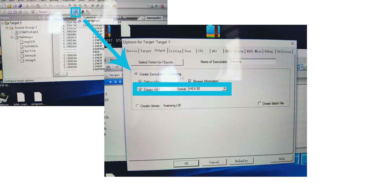
● 5. Automatically create a hex file for programming. Click the target, and create HEX file.
programming
I used STC-ISP (download link to program.
● 1. I downloaded a later version from stcmcu.com and installed it.
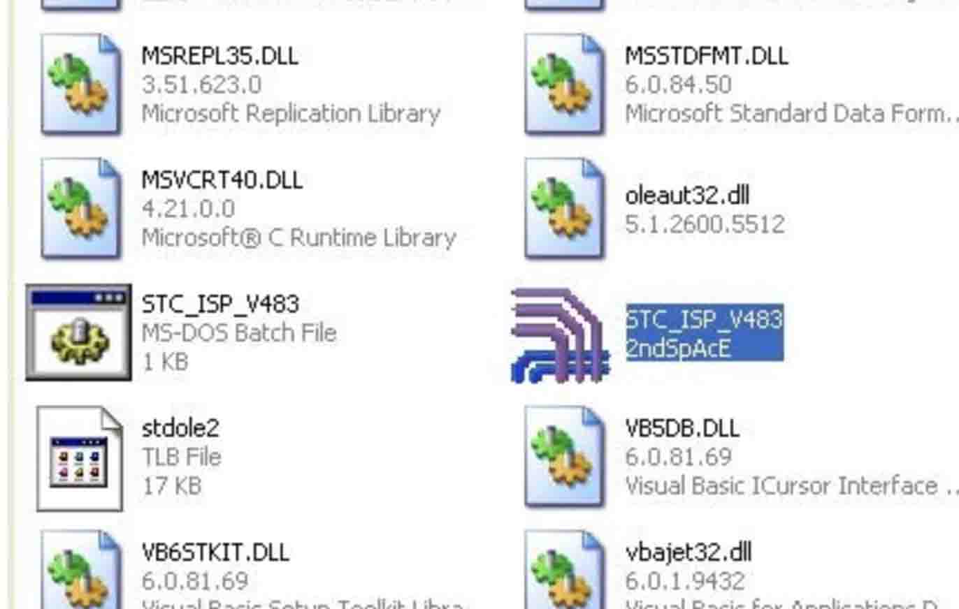
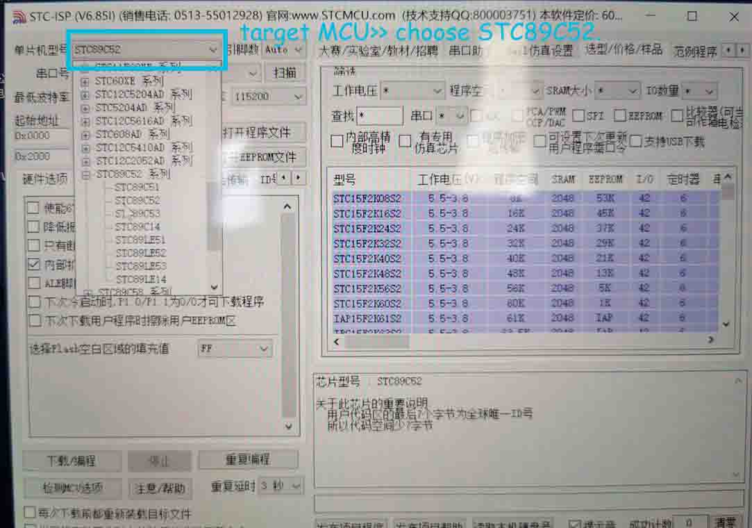
● 2.Start the STC-ISP software(double click STC-ISP) Select the target MCU>> choose STC89C52.
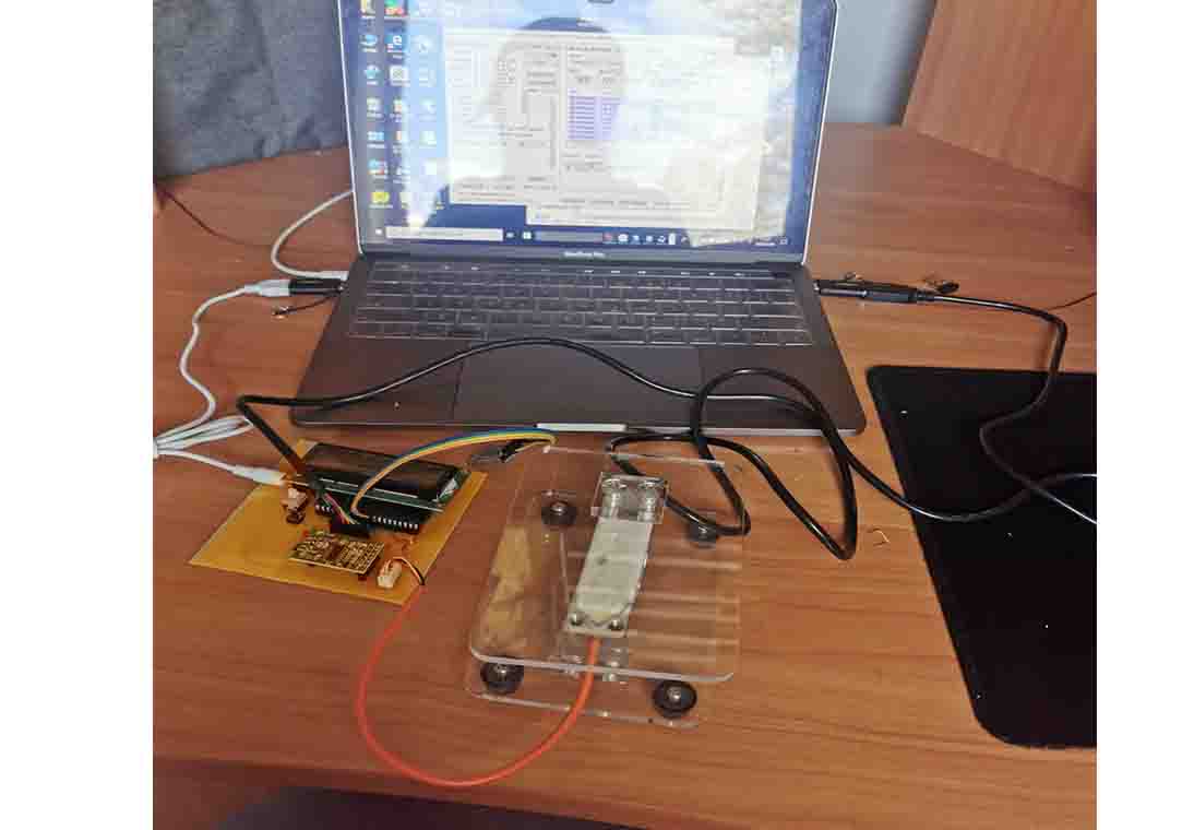
● 3. Connect the board to my laptop.
● 4. Open the hex file, Configure the COM port, and set up the Highest baud rate and lowest baud rate.
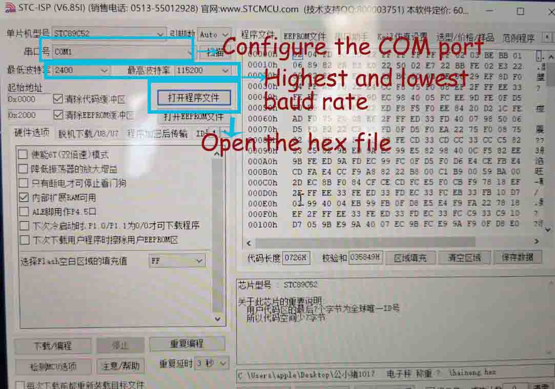
● 5. Press download and programming.
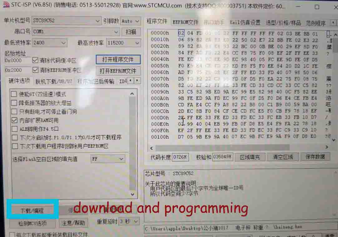
● 6. Switch on the power on my board. (That is important, although I do not know the reason, everyone mentioned that, before pressing the download, the power switch should turn off. )
After....
Finally.....my board is working, when I pressed the power switch, it measured the weight, the LCD shown the measured weight is 0g, and beep few seconds. When I put something on the surface, it measured the weight again. Because the item weight is more than setting(100g), it would not beep, just shown the weight.
Create an APP
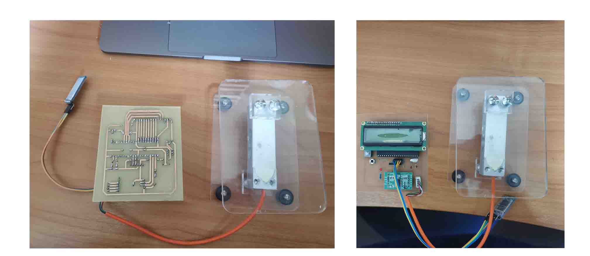
I created an APP for my final project, and employed Bluetooth to connect my phone and my board to measure the item weight, when the weight is less than 100g, my phone shown the weight and remind me.
I am using the board that contains a HX711 BALANCE MODULE WITH LOAD CELL, STC89C52 microcontroller, LCD1602, HC-5 BLUETOOTH. my goal is present the data coming from the load cell directly to the mobile phone.
The detail of board programming
I am using E4A to create the APP for my final project. E4A is an all-Chinese Android programming language that was officially released on June 1, 2013. It is positioned for enterprises, webmasters, developers, network companies, various handheld devices, etc., based on Android system APP development. The programming of Android APP code in the language is very in line with the programming thinking habits of the Chinese people and can make the Chinese people extremely easy to use. E4A will eventually develop into the world’s first full Chinese Android APP development language with simple and powerful applications.download link
I choose E4A to create the App, because it is easy to create and the language is Chinese that familiar with me. I also learned the code and how to use the software online. This is a forum and you need to register first. When you register, you can search for all the tutorials you need. However, please note that if you need to download code, you need to become a VIP user, which means you need to pay for it.
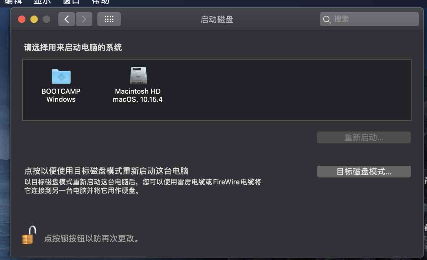
● Step1. Download E4A software. It is only for Windows system and free, I am glad that my laptop is a dual system and I can switch the system freely.
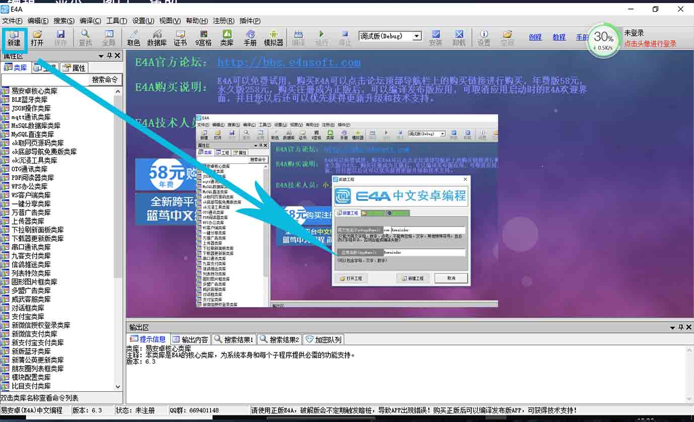
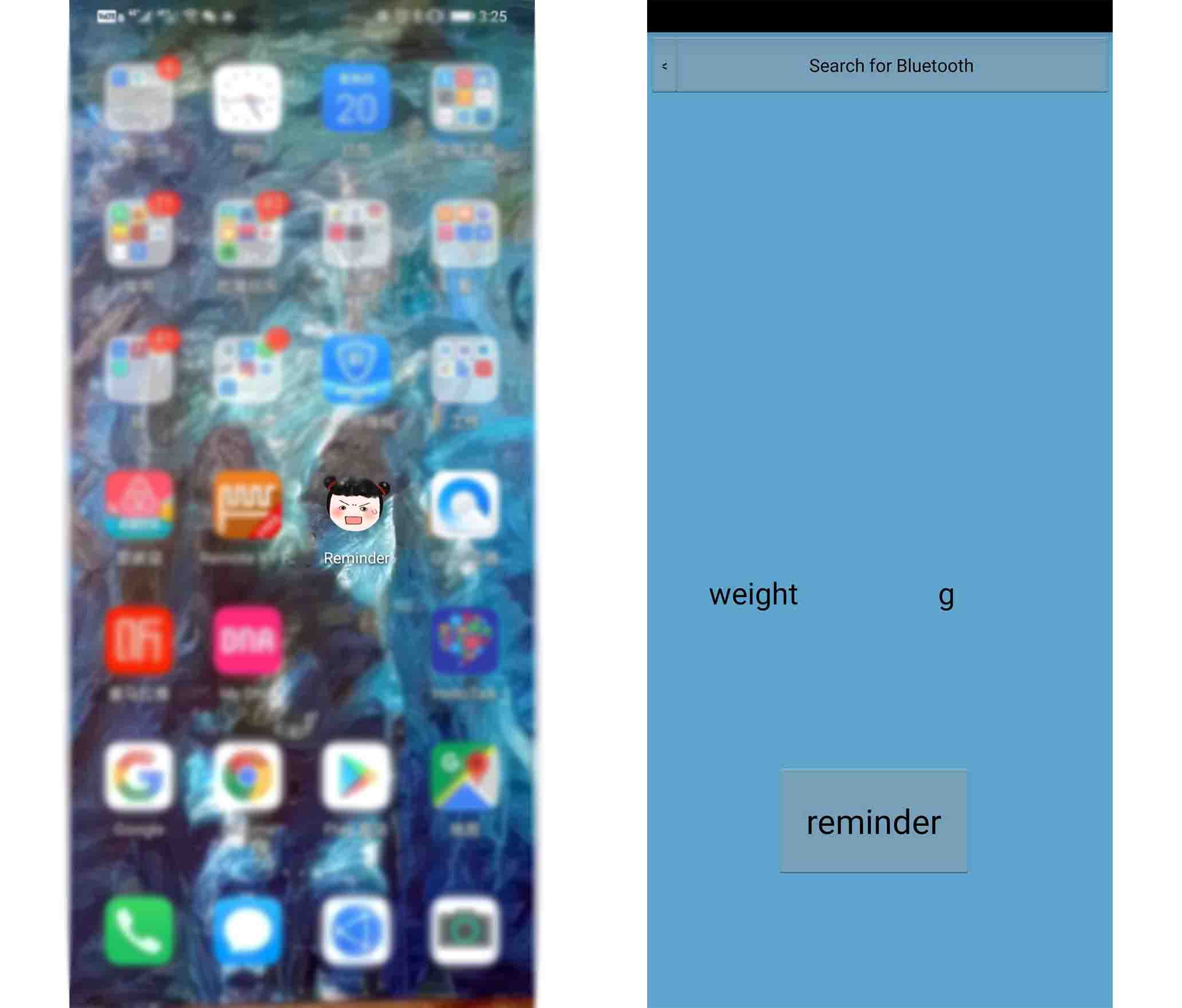
● Step2. Open the software, and create a new project and store it in my computer, also text the App name and package name.
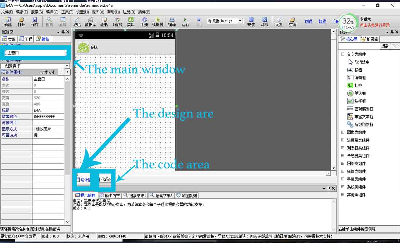
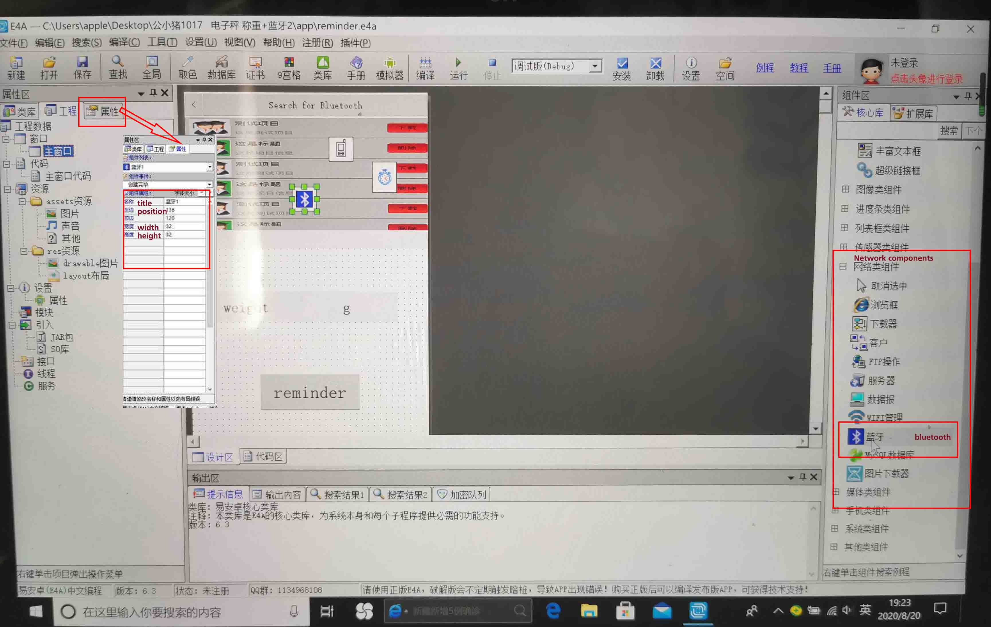
Then the software shown like the following figure.The left window displays the properties of the component, such as color, display style, location, height, and width.The bottom window displays various prompts and search functions.The window on the right is the various components and their sub-menus. Such as text component, graphics component, progress bar component, sensor component, network component, media component and so on.
● Step3. Create the button for searching the bluetooth, and code for the button.
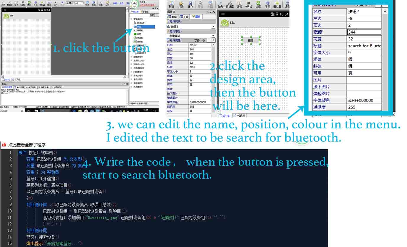
The first, I created the button shown searching the bluetooth. I clicked the button under the text component sub-menu, then clicked the design area, the button will be in the main design area automatically.
Also, I can set up the properties of the button that I created by click the left window. In the left window, I can set the button name, the position and height and width, also the font, color, size and transparency of the text.
Then, writing code in the code area. For the searching the Bluetooth, when it is pressed, start to search bluetooth.
The main part is to create the bluetooth, and write the code.
Firstly, I searched the bluetooth in sub-menu of Network components in the right window , and clicked the design area. In the left window, we can set the title, position, height and width.
Secondly, when I right click the Bluetooth, we can see the menu here, related to it. When I click the second one, that is the code related to Bluetooth, also in the bottom area, it is the code and explanation in the following figure.
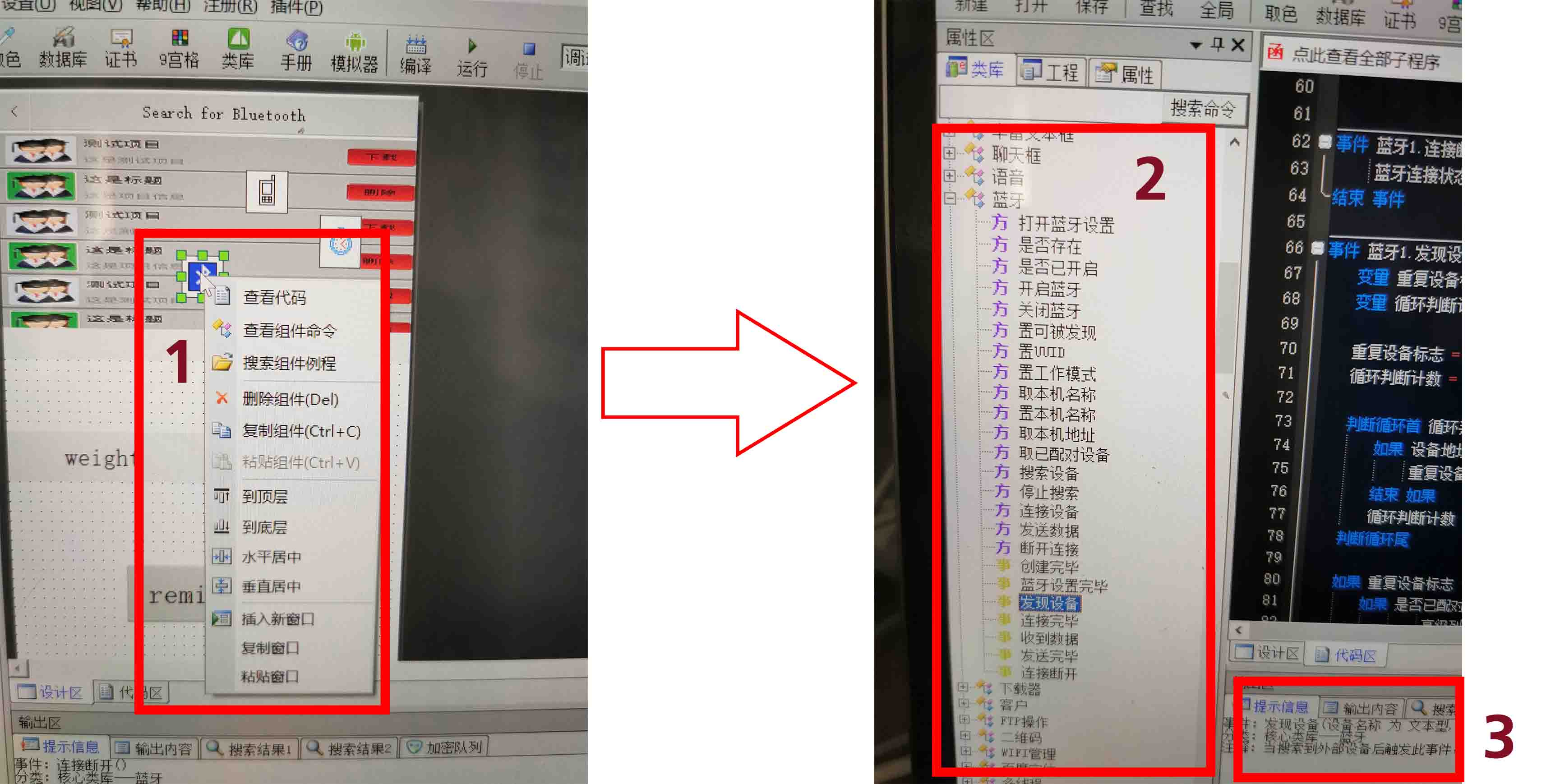
Third, I clicked the code area, and write code here. For example as the following figure.
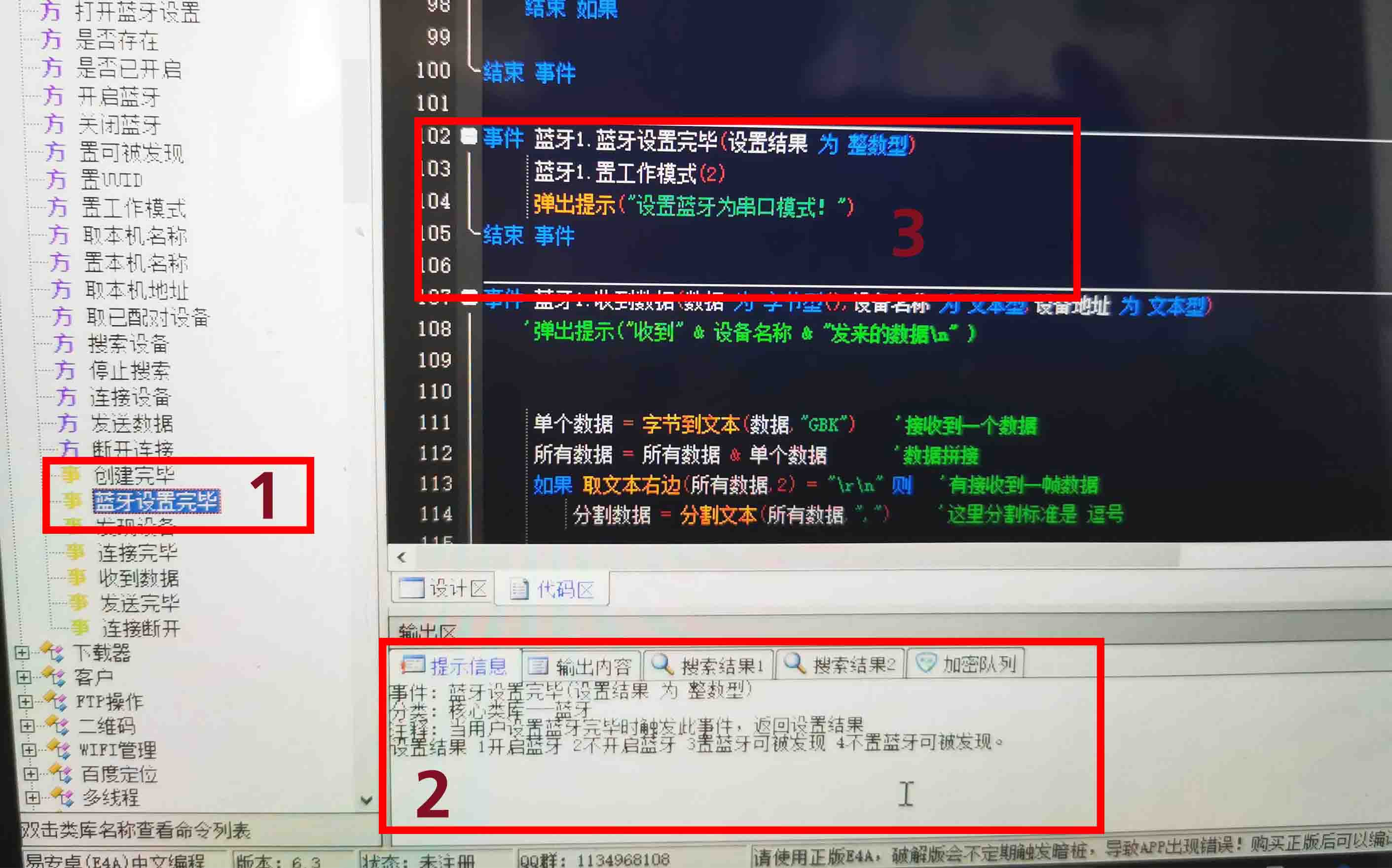
In step 1, A list of the series of Bluetooth codes, such as searching Bluetooth, turn on Bluetooth and so on. I clicked the define function bluetooth1.setup(int set_result).
In step 2, the code explanation.
In step 3, the code area for setting Bluetooth to serial-port mode.
事件 蓝牙1.蓝牙设置完毕(设置结果 为 整数型) # define function bluetooth1.setup(int set_result)
     蓝牙1.置工作模式(2) # bluetooth1.mode(2) ## set the bluetooth1 to serial port mode
     弹出提示("设置蓝牙为串口模式!") #print("Set Bluetooth to serial-port mode")
结束 事件 # end function definition
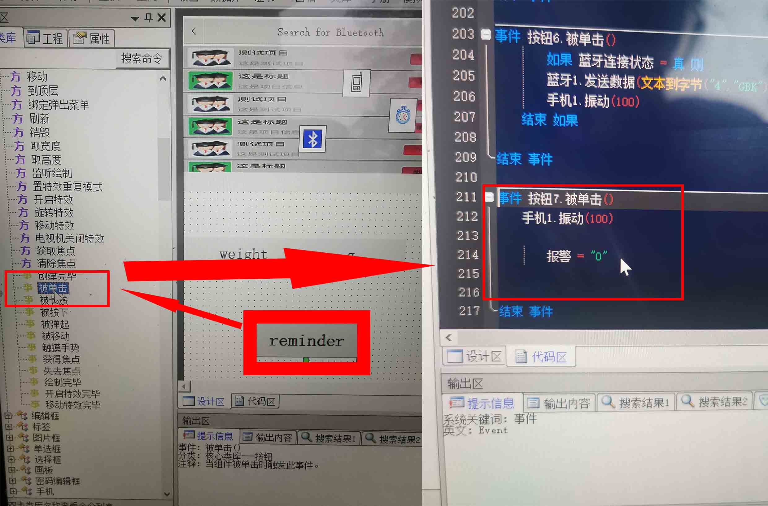
● Step4. Using the same way to create other button, text, and and write the code.
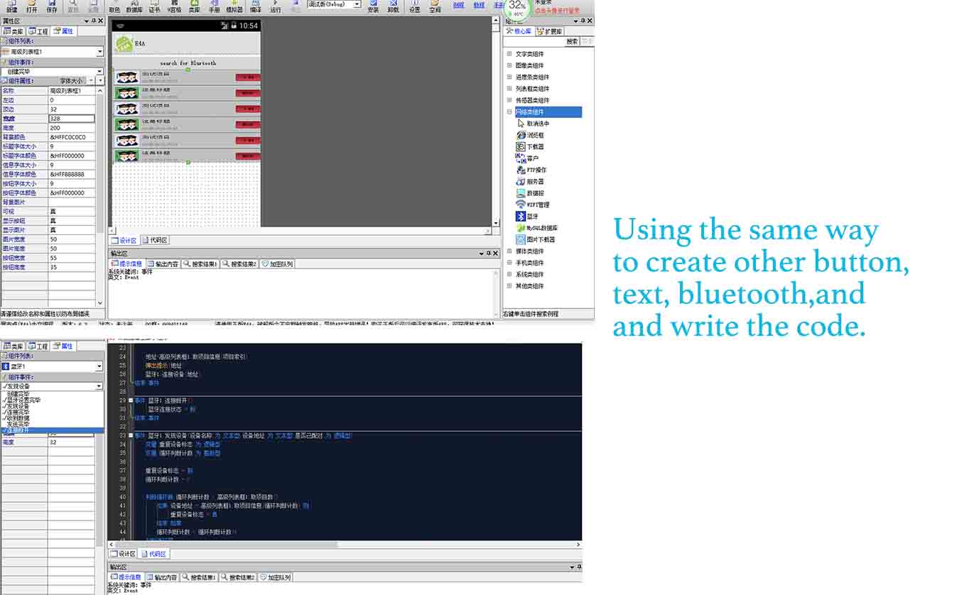
For example, creating a button, and setting when it pressed, writing code to be ” the first line: when it has been pressed, the second line: the phone is vibrating for 100 milliseconds, the third Line: the alarm to be false, which means stop”.
Also, I sending the weight as a string via Bluetooth.
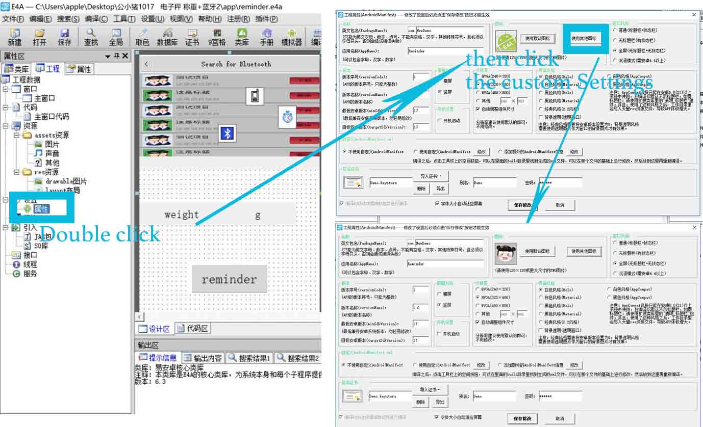
● Step5. Because I designed a Cartoon portraits for the presentation, so I would like to use it to be the ICON for the APP. So I click the attribute, and choose the icon that I designed in presentation week from default to custom Settings.
'下面开始定义蓝牙用到的一些变量 # The following section is for defining variables
变量 蓝牙连接状态 为 逻辑型 # bool blueToothStatus
变量 单个数据 为 文本型 # str one_input
变量 所有数据 为 文本型 # str all_input
变量 分割数据 为 文本型() #str divided_input
变量 报警 为 文本型    # str alarm


'下面定义报警部分  #Defining the alarm for the device
变量 设备报警 为 整数型  # int device_alarm

'下面定义退出用到的变量  # Defining the variables for quitting the app
变量 启动时间 为 长整数型 # long initiate_time


事件 主窗口.按下某键(键代码 为 整数型,传址 屏蔽 为 逻辑型) # define function when pressing some key on the main interface, set the var keyboard_input as integer, set addressing passing as bool
    如果 键代码 = 返回键 则  #if keyboard_input == "return"  (return button)
        如果 取启动时间() - 启动时间 >2000 则 # if actual-initiate_time.() - initiate_time >2000  [actual_initiate_time.() is a built-in function]

            弹出提示("再按一次退出程序")# print("Tap again for quitting the app")
            启动时间 = 取启动时间() #initiate_time = actual_initiate_time.()
        否则 # else
            结束程序() #break
        结束 如果 #end if
    结束 如果 #end if
结束 事件 # #end function definition

事件 主窗口.创建完毕() #define function main_interface.built()
    报警 = "1" # alarm ="1"
    主窗口.背景颜色=&HEE519FC9 #main_interface.color(&HEE519FC9)
    如果 蓝牙1.是否存在() = 假 则 #if bluetooth1.exist() == false
        信息框("信息","本机找不到蓝牙设备,程序将退出!","确定") # print("Notice", "No Bluetooth Device, Quitting the App!", "OK")
        结束程序() # break
    否则 #else
        如果 蓝牙1.是否已开启() = 假 则 #if bluetooth1.connected()== false
             蓝牙1.开启蓝牙() # bluetooth1.connected()
        否则 #else
             蓝牙1.置工作模式(2) #bluetooth1.mode(2) ##set bluetooth1 to mode 2, which is serial-port mode
             弹出提示("设置蓝牙为串口模式!")  #print("Set Bluetooth to serial-port mode")
        结束 如果 #end if
    结束 如果 #end if

    设备报警 = 0 #alarm = 0

结束 事件 # end function definition

事件 高级列表框1.表项被单击(项目索引 为 整数型) #define function  superior_list.itemclicked(int item_index) ## When an item in the list is clicked, set the index as integer
    变量 地址 为 文本型 # str item_address


    蓝牙1.断开连接() # bluetooth1.disconnect()

    地址=高级列表框1.取项目信息(项目索引)# item_address = superior_list.iteminformation (index) ## assign the index as the address of the clicked item
    弹出提示(地址) # print(item_address)
    蓝牙1.连接设备(地址) # bluetooth1.connect(item_address)
结束 事件 #end function definition


事件 蓝牙1.连接断开() # define function bluetooth1.disconnect()
     蓝牙连接状态 = 假 # blueToothStatus == false
结束 事件 #end function definition

事件 蓝牙1.发现设备(设备名称 为 文本型,设备地址 为 文本型,是否已配对 为 逻辑型) #define function bluetooth1.discover(str device_name, str device_address, bool pair_status )
    变量 重复设备标志 为 逻辑型 # bool repeated_paired_device
    变量 循环判断计数 为 整数型 # int repeat_count

    重复设备标志 = 假 # repeated_paired_device == false
    循环判断计数 = 0 # repeat_count = 0

    判断循环首 循环判断计数 < 高级列表框1.取项目数() # if repeated_paired_device < superior_list.itemcount() ## if the repeated paired device is less than the items in the superior_list
        如果 设备地址 = 高级列表框1.取项目信息(循环判断计数) 则 if device_address = superior_list.iteminformation(repeat_count)
             重复设备标志 = 真 # repeated_paired_device == true
        结束 如果 #end if
        循环判断计数 = 循环判断计数+1 # repeat_count += 1
    判断循环尾 #break

    如果 重复设备标志 = 假 则 # if repeated_paired_device == false
        如果 是否已配对 = 真 则 # if pair_status == true
                 高级列表框1.添加项目("Bluetooth_.png",设备名称 & "(已配对)" ,设备地址,"","") # superior_list.add("Bluetooth_.png", device_name & "paired", device_address, "","")
            否则 #else
                 高级列表框1.添加项目("Bluetooth_.png",设备名称 & "(未配对)" ,设备地址,"","") # superior_list.add("Bluetooth_.png", device_name & "unpaired", device_address, "","")
        结束 如果 # end if

    结束 如果 #end if

结束 事件 #end function definition

事件 蓝牙1.连接完毕(连接结果 为 逻辑型,设备名称 为 文本型,设备地址 为 文本型,连接模式 为 整数型) # define function bluetooth1.connected(bool conn_result, str device_address, int conn_mode)
    如果 连接结果 = 真 则 # if conn_result == true
        蓝牙连接状态 = 真 # blueToothStatus = true
        弹出提示("与设备 " & 设备名称 & " 连接成功!") # print("Successfully connected to" & device_name)
    否则 #else
        蓝牙连接状态 = 假 # blueToothStatus = false
        弹出提示("与设备 " & 设备名称 & " 连接失败!") # print("Unable to connect to" & device_name)
    结束 如果 #end if

结束 事件 end function definition

事件 蓝牙1.蓝牙设置完毕(设置结果 为 整数型) # define function bluetooth1.setup(int set_result)
     蓝牙1.置工作模式(2) # bluetooth1.mode(2) ## set the bluetooth1 to serial port mode
     弹出提示("设置蓝牙为串口模式!") #print("Set Bluetooth to serial-port mode")
结束 事件 # end function definition

事件 蓝牙1.收到数据(数据 为 字节型(),设备名称 为 文本型,设备地址 为 文本型) #define function bluetooth1.receivedata(str data, str device_name, str device_address)
    '弹出提示("收到" & 设备名称 & "发来的数据\n" ) # print("Received Data from" & device_name)


     单个数据 = 字节到文本(数据,"GBK")    '接收到一个数据 # one_input = byte_to_str(data, "GBK")  ##receiving a single input
     所有数据 = 所有数据 & 单个数据       '数据拼接 # all_input = all_input & one_input ## cumulating all input
     如果 取文本右边(所有数据,2) = "\r\n" 则   '有接收到一帧数据 # if all_inputp[-2] ==“\r\n” ## when reach the end of a line (\r\n is the default line separator)
         分割数据 = 分割文本(所有数据,",")     '这里分割标准是 逗号 # divided_input = text.divide(all_input, ",") ## text.divide() is a built-in function.
       # In this step, when detecting the end of the line (\r\n), separate all_input by comma with the built-in function text.divide()

         如果 取数组成员数(分割数据)>2 且 取文本右边(分割数据(0),4)="Data"  则  '到这一步,基本数据就接收对了,可以开始处理了 # if counting(divided_input) >2 AND divided_input(-4)="Data"
     # The purpose of this step is to verify whether divided_input contains >2 elements and whether the right most four strs are "Data", if so, the data are in right format
             标签7.标题 = 分割数据(1) # tag7. title() = divided_input(1)
             如果 分割数据(2)="1" 则 # if divided_input(2) == "1"
                如果 报警 = "1"  则 # if alarm == "1"
                    手机1.振动(100) # phone1.viberate(100)

                     播放音乐("666666.mp3") # play.("666666.mp3")

                    结束 如果 # end if

            否则 # else
                报警 = "1" # alarm = "1"
            结束 如果 "end if"


         结束 如果  '数据处理完毕 # end if ##data processed

         所有数据 = "" '在实际测试发现,推荐传输速率最快100ms/n,否则因为太快,接收的时候是两遍数据 # all_input =""
             ## In this step, the upload rate should be 100ms/n, otherwise the data will be received twice
     结束 如果 #end if
结束 事件# end function definition


事件 按钮1.被单击() # Define function button1.clicked()
    变量 已配对设备组 为 文本型() # str paired_devices
    变量 取已配对设备集合 为 集合 # group paired_devices.group() ## Retrieve the paired_devices and save in the format of group
    变量 i 为 整数型 # int i
    蓝牙1.断开连接() # bluetooth1.disconnect()
    高级列表框1.清空项目() # superior_list.clear() clear the list
    取已配对设备集合 = 蓝牙1.取已配对设备() # paired_devices= bluetooth1.paired_devices()
    i=0
    判断循环首 i<(取已配对设备集合.取项目总数()) # if i < paired_devices.counting() ## if i is smaller than the amount of paired devices
            已配对设备组 = 取已配对设备集合.取项目(i) # paired_devices = paired_devices.item(i)
            高级列表框1.添加项目("Bluetooth_.png",已配对设备组(0) & "(已配对)",已配对设备组(1),"","") superior_list.add("Bluetooth_.png", paired_devices(0)& “paired” ,"paired_devices(1)")
            i = i + 1
    判断循环尾# end if
    蓝牙1.搜索设备() # bluetooth1.searchdevice()
    弹出提示("开始搜索蓝牙...") # print("Begin to Search for Bluetooth Device")
结束 事件 # end function definition


事件 按钮2.被单击() # Define function button2.clicked()
    如果 蓝牙连接状态 = 真 则 # if blueToothStatus == true
        蓝牙1.发送数据(文本到字节("1","GBK")) # bluetooth1.send(str_to_byte("1","GBK"))
        手机1.振动(100)# phone1.viberate(100)
    结束 如果 #end if
结束 事件 # end function definition

事件 按钮3.被单击()  # Define function button3.clicked()
    如果 蓝牙连接状态 = 真 则 # if blueToothStatus == true
        蓝牙1.发送数据(文本到字节("2","GBK")) # bluetooth1.send(str_to_byte("2","GBK"))
        手机1.振动(100)# phone1.viberate(100)
    结束 如果 #end if
结束 事件 # end function definition

事件 按钮4.被单击() # Define function button3.clicked()
    如果 蓝牙连接状态 = 真 则 if blueToothStatus == true
        蓝牙1.发送数据(文本到字节("3","GBK")) # bluetooth1.send(str_to_byte("3","GBK"))
        手机1.振动(100)# phone1.viberate(100)
    结束 如果 #end if
结束 事件 # end function definition

事件 时钟1.周期事件() # Define function clock,.periodic() # define a periodic event for the clock
    如果 设备报警 = 1 则 # if device_alarm == 1
        手机1.振动(100)  # phone1.viberate(100)

         播放音乐("fengmingqi.mp3") # play.("fengmingqi.mp3")
    结束 如果 # end if


结束 事件 end function definition

事件 手机1.电池状态改变(状态 为 整数型,剩余电量 为 整数型,温度 为 整数型) # define phone1.batterystatus(int b_status, int left_battery, int temp)

结束 事件 #end function definition

事件 标签7.被单击() # define function tag7.clicked()

结束 事件 #end function definition

事件 按钮5.被单击() # define function button5.clicked()
    结束程序() #break
结束 事件#end function definition

事件 按钮6.被单击() # define function button6.clicked()
        如果 蓝牙连接状态 = 真 则 # if blueToothStatus == true
        蓝牙1.发送数据(文本到字节("4","GBK")) bluetooth1.send(str_to_byte("4","GBK"))
        手机1.振动(100)# phone1.viberate(100)
    结束 如果 #end if
结束 事件 # end function definition

事件 按钮7.被单击() #define function button7.clicked()
    手机1.振动(100) # phone1.viberate(100)

        报警 = "0" # alarm ="0"


结束 事件 #end function definition
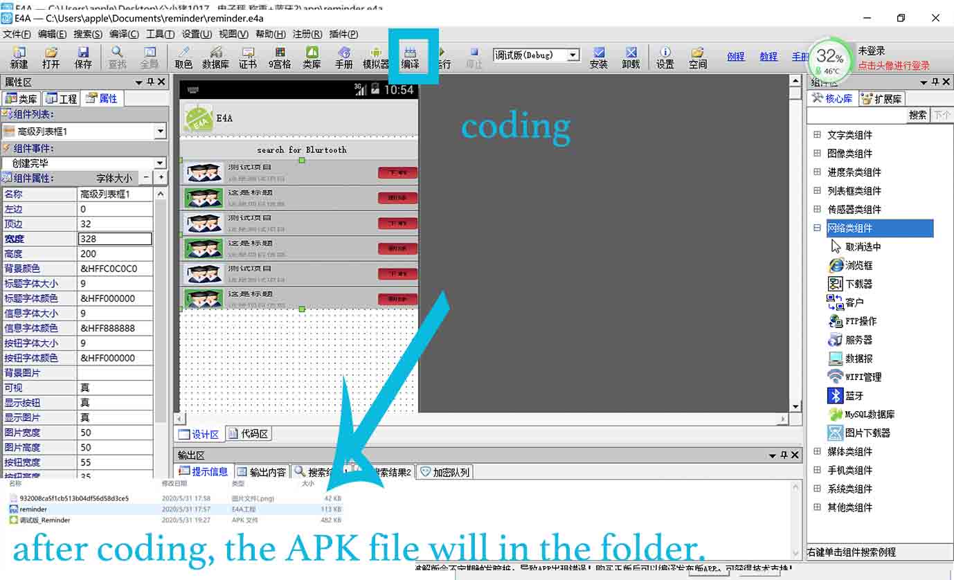
● Step6. Click coding. It will automatically create the APK file (for E4A, it can not export the code, just APK file), and save it in my computer.
● Step7. I have been designed and programmed my board that included the Bluetooth in the input device week and output device week, that means when I download the app to my phone and install it, it will be working.
● Step8. I used WeChat to send the APK file from my computer to my phone, and when I click it, it can be installed in my phone.
Finally, I tested it.
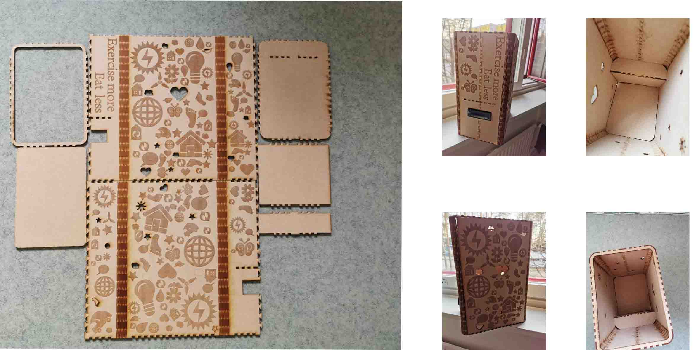
Design
Laser cutting design
I choose laser cutting for my final project.
● 1. Open the Adobe Illustrator, using Pen to draw the outline of the container.
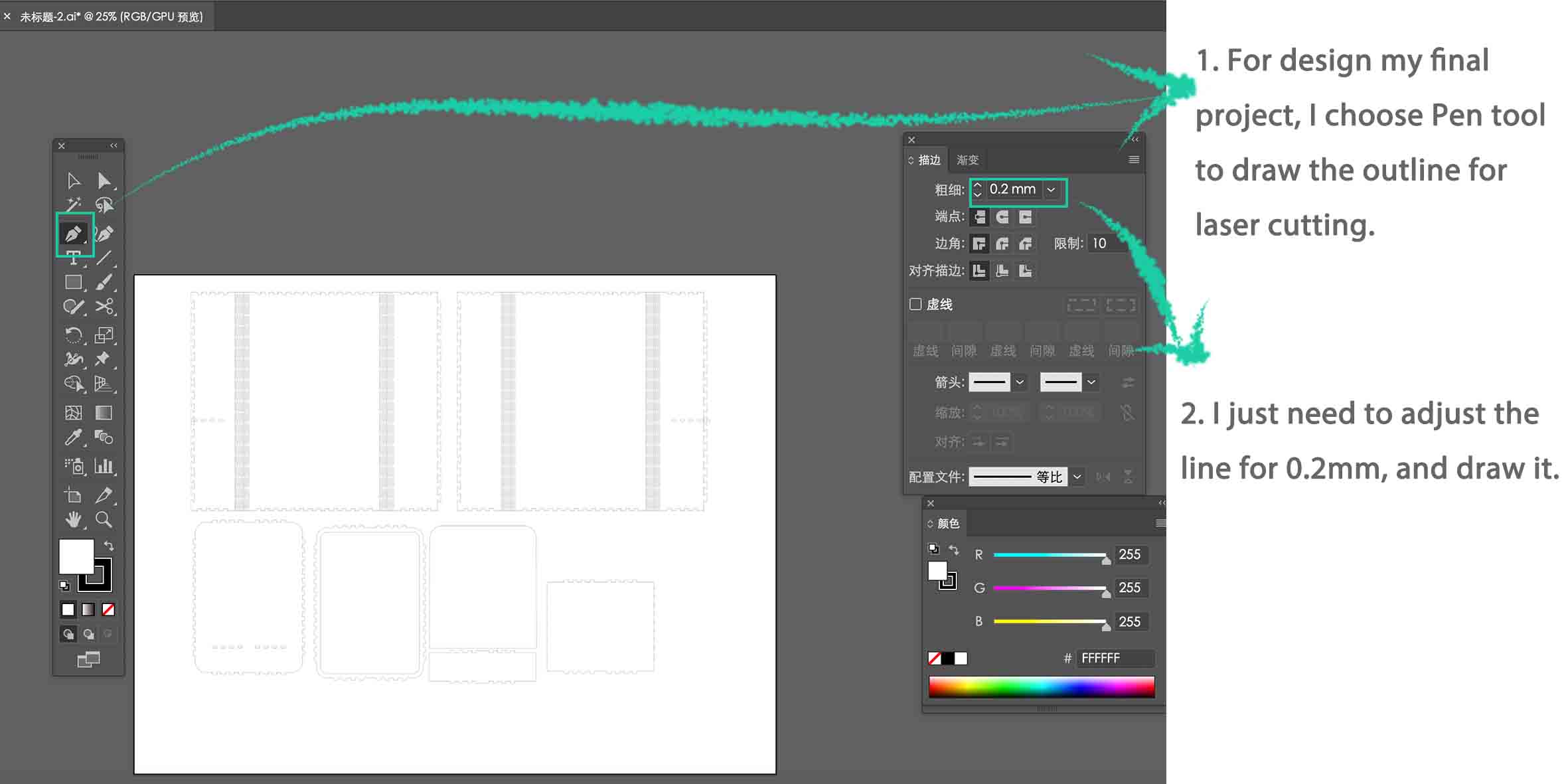
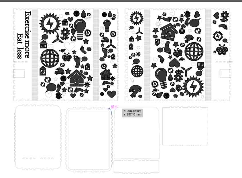
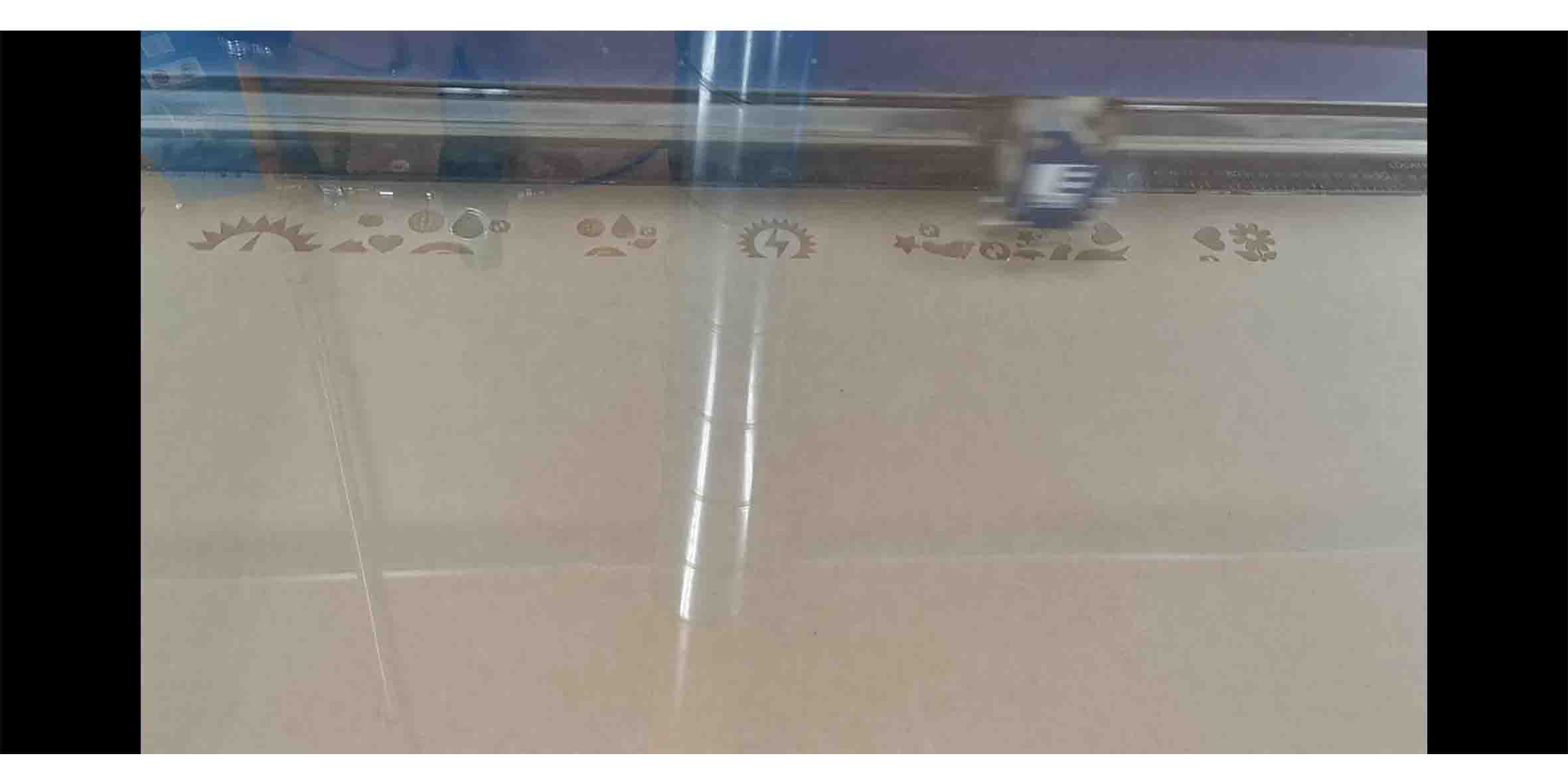
● 2. Using Pen to draw the interesting patterns, and because of the virus, I stayed at home for nearly 2 months. I found that I need to lose weight, so I decided to use the container to store rice. Also, using the Text tool to write some words encourage me to keep on shape.
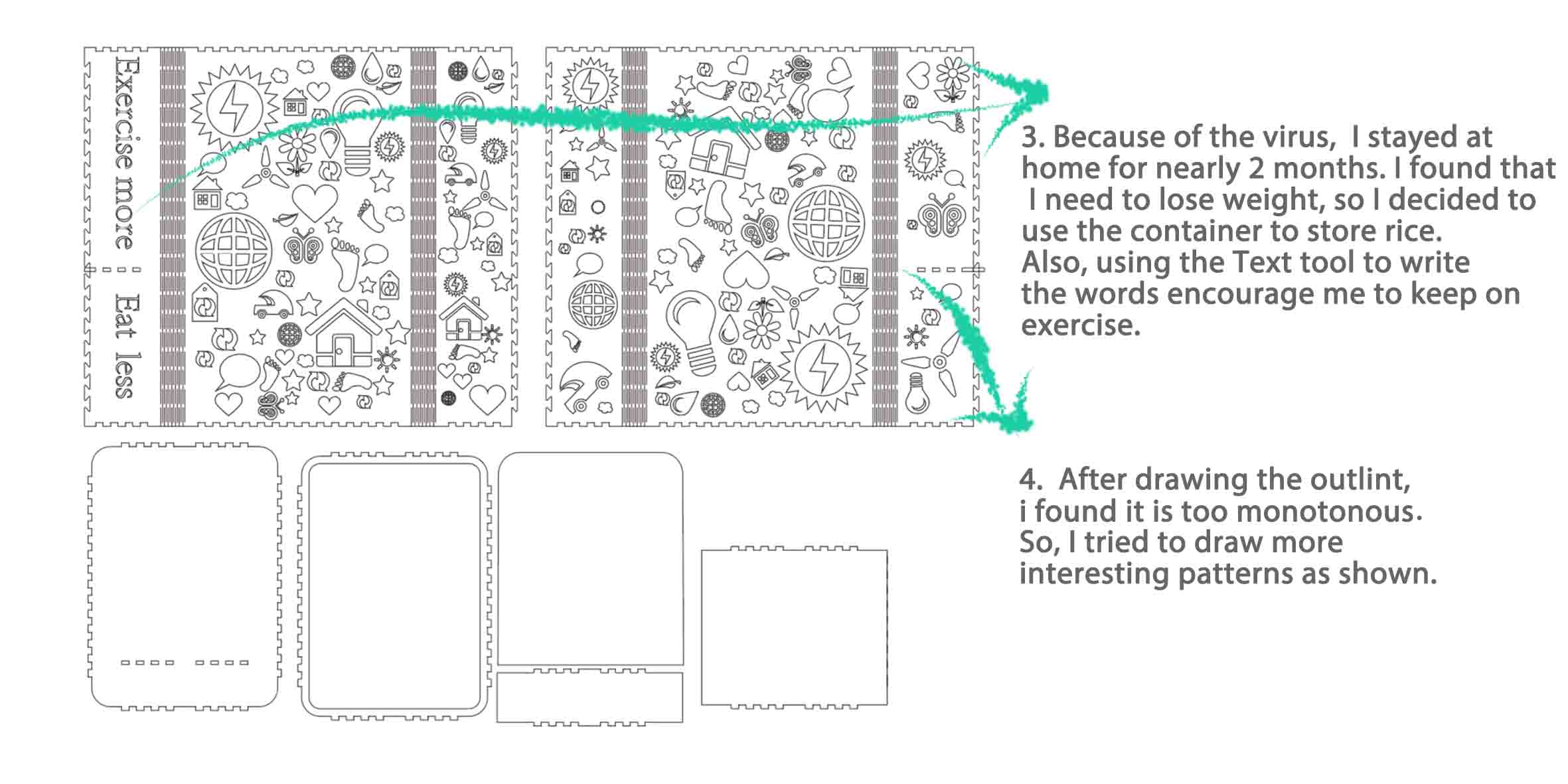
Then, I adjusted it, because if all the patterns are hollow, the stability of the container will be affected. Also, I remember the line should be 0.02mm, so I adjusted it.
● 3. Set up the laser cutter, and cut the box for my project.
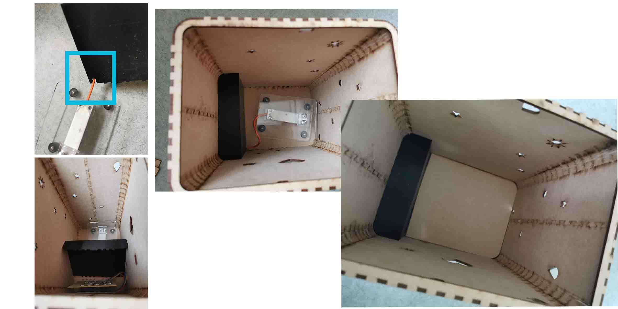
3D design
Last week, I knew the 3D design is mandatory, and the instructor mentioned I can design something for board. Then I decided to design a Disjunctive space for my board to protect my board.
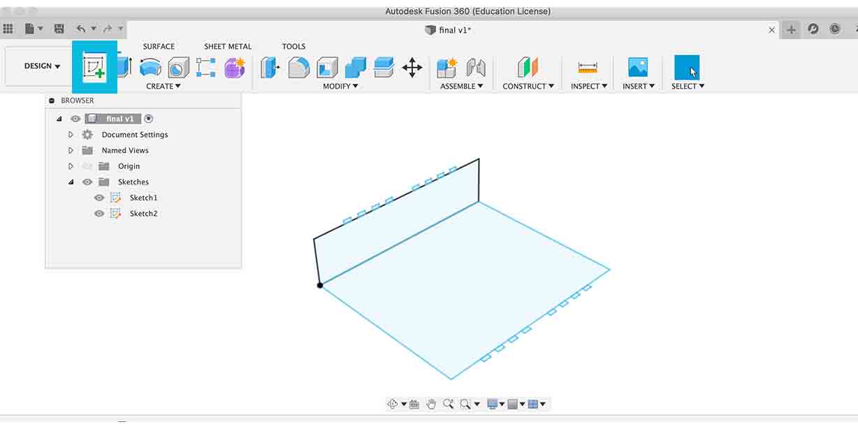
● 1. Create a sketch in Fusion 360.
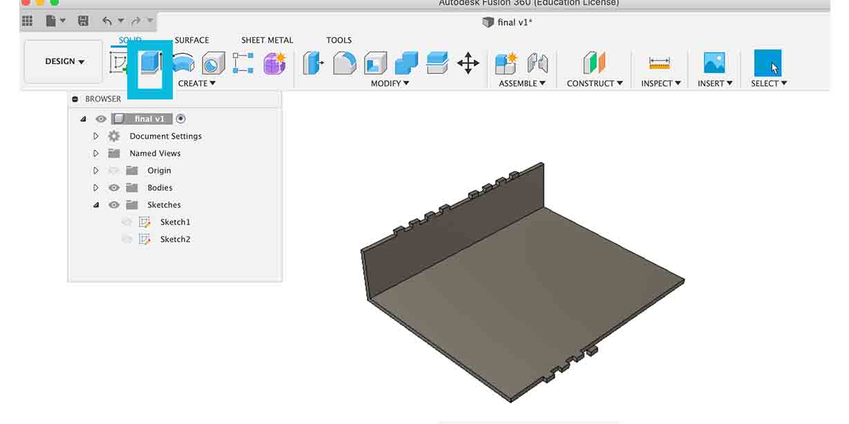
● 2. Extrude the sketch in Fusion 360.
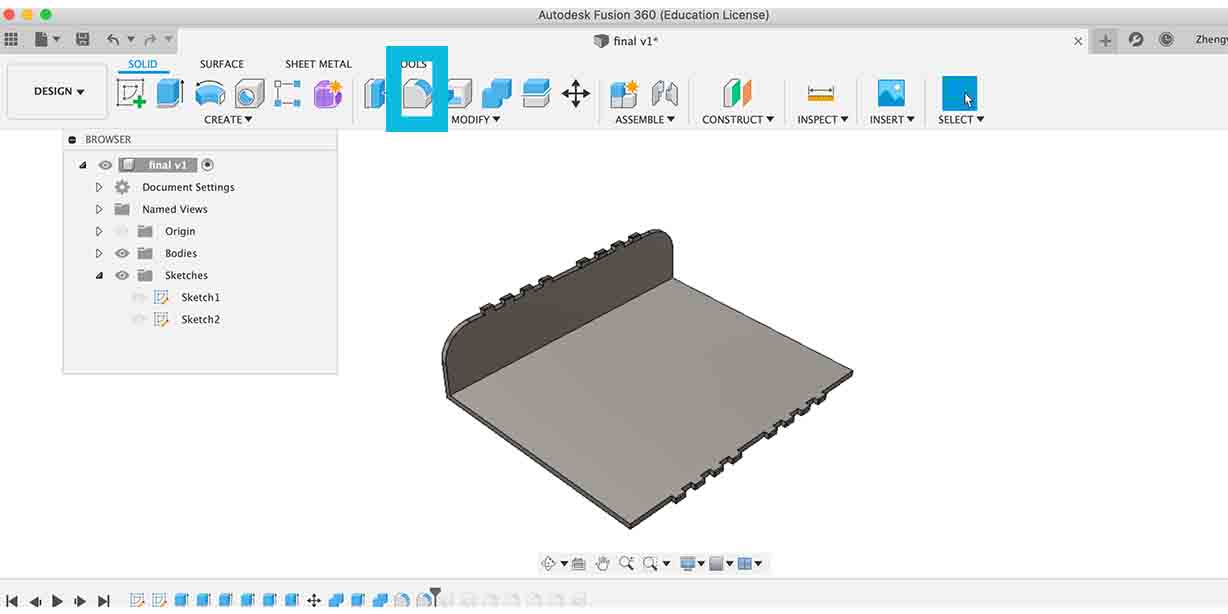
● 3. Fillet the edges to fit my container.
● 4. Make a hole that allow the wires to connect the load cell, my board and power.
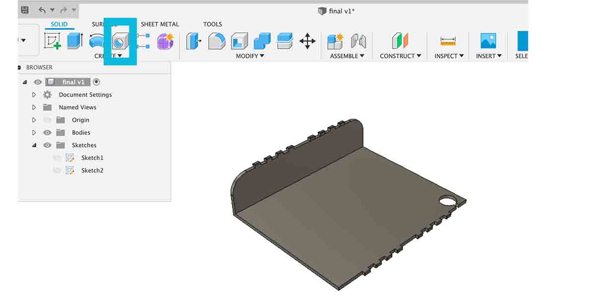
● 5. Export it to be stl file.
● 6. Open GrabCAD Print software: File > New project > Add models > Choose the file, also I set Model settings: I didn’t change the default setttings > Part filling style, Infill density 36%, Body Thickness 1.52, and Infill Angle 45 °C. Support Settings :smart.
Then I export it to be CMB file, and open it in control center. Insert the CMB file, and place it in the correct position also build job.
For the printer machine, I placed the base sheet in, and when the state shown green, press build and play.
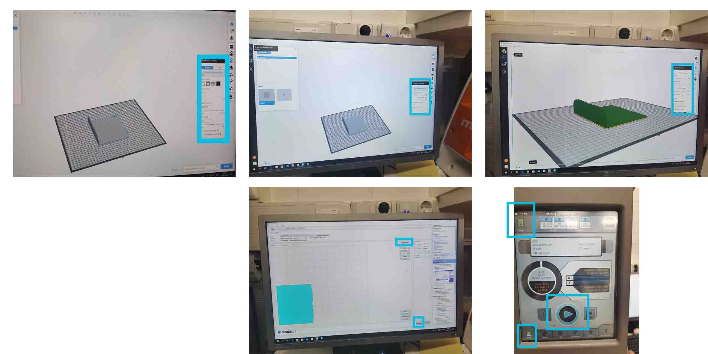
After 2 hours, I removed the support material.
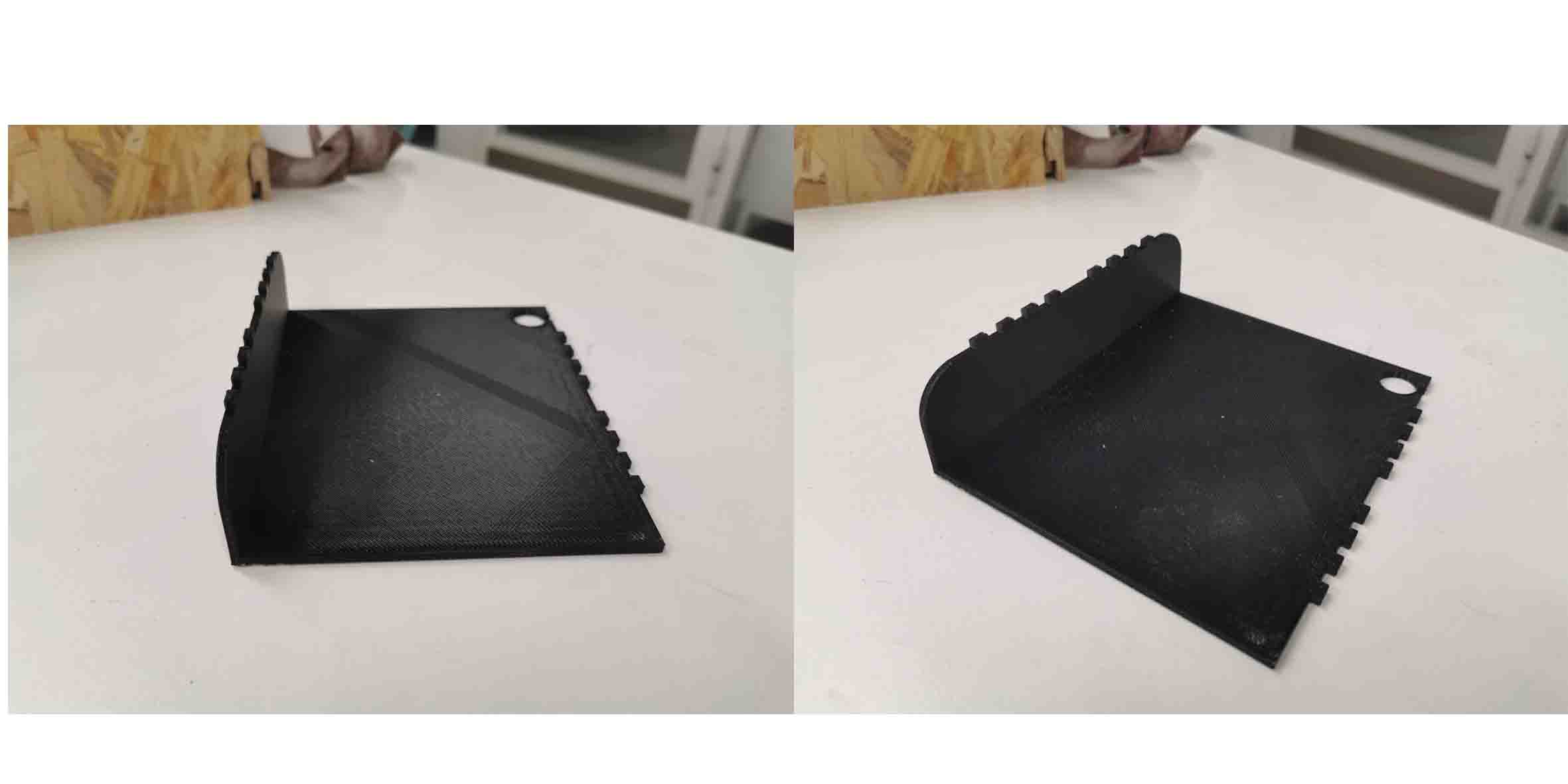
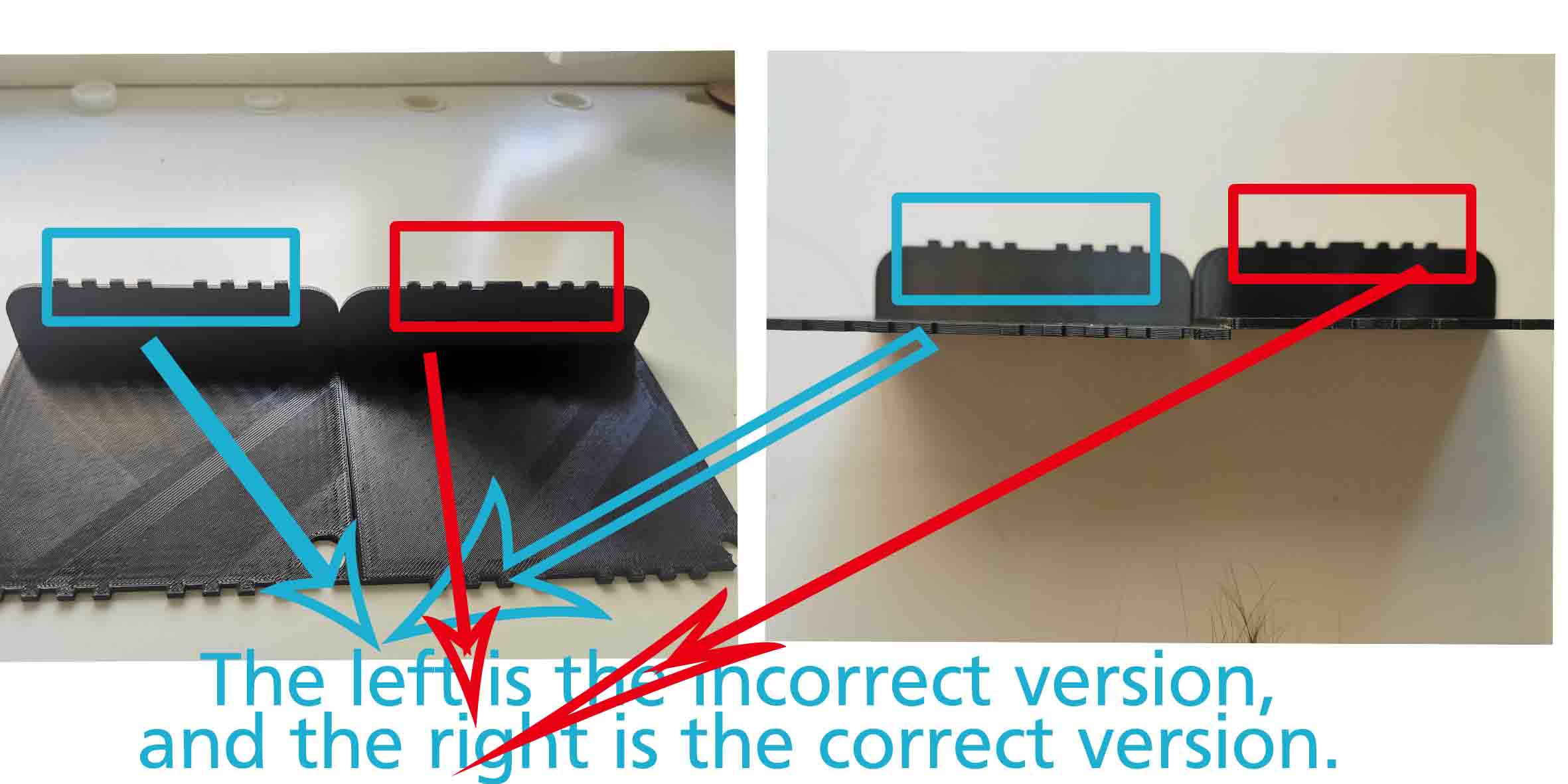
When I tried to assemble the box, I found the 3D part has mistakes. Then I redesigned it, and printed it again using the same process.
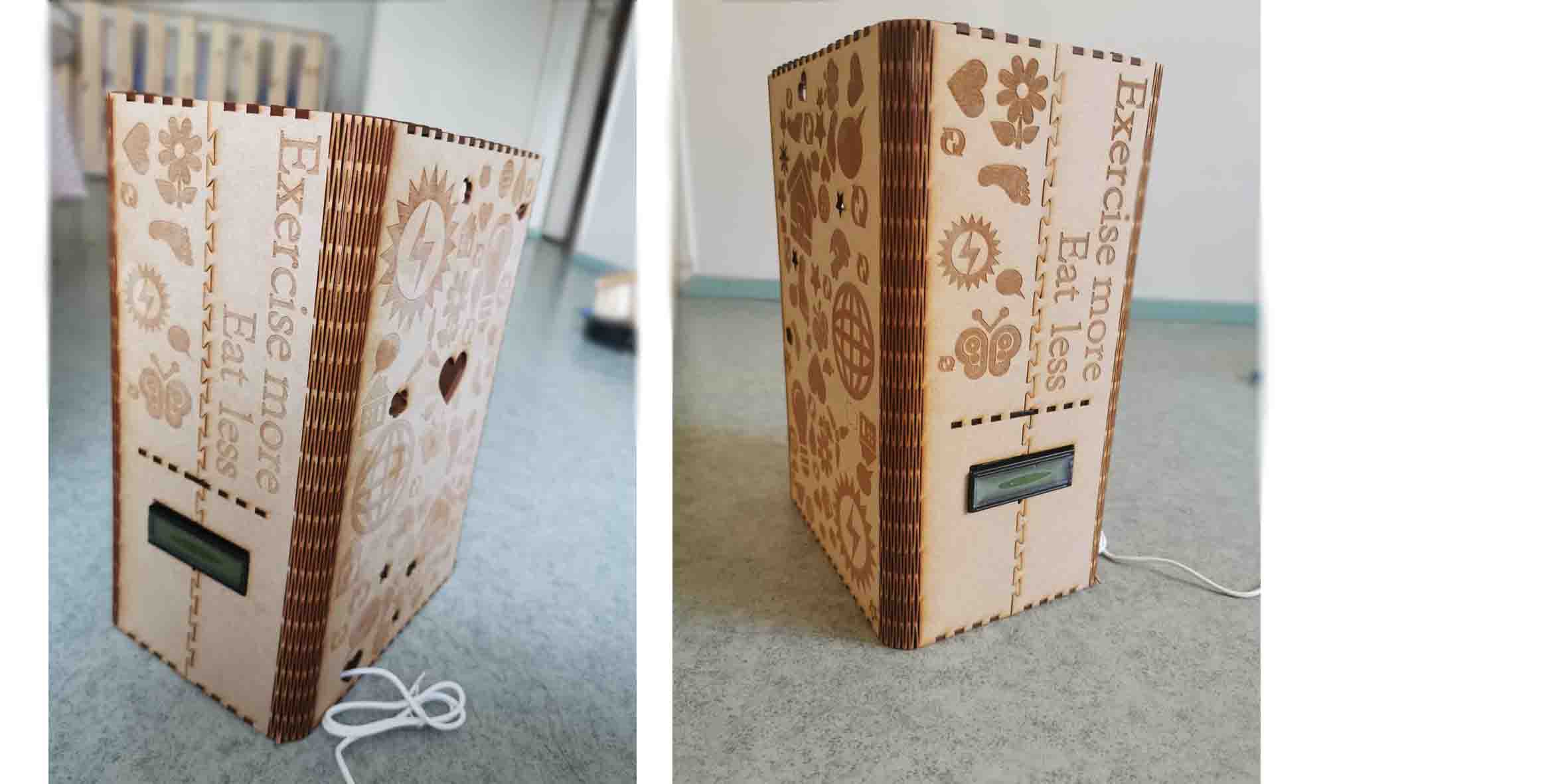
Assemble the box
Licenses
After investigating different choices in protecting my potential Intellectual Property, I decide to make my design publically available on Thingiverse and the complete design on WikiHow.
A major reason that encourages me to make such a decision has been that my project is based on the helpful from many previous free tutorials, without which I would not figure out how to achieve my design.