8. Embedded Programming
Week’s Assignments
Individual assignment:
● read a microcontroller data sheet
● program your board to do something, with as many different programming languages and programming environments as possible
Group assignment:
● Compare the performance and development workflows for other architectures
Group assignment
Group:
● - Xinhui Hu
● - Zhengya Gong
● - Yazan Barhoush
● - Noora Nyberg
The details of group assignment
Individual assignment:
● Read a microcontroller data sheet
I started out by getting a copy of the data sheet for the ATtiny 412 microcontroller. It is incredible that a microcontroller has so many features that it takes 479 pages to explain. I found a lot of useful information.
I learned that so many information about the product is included in Data Sheet.
● Microcontroller is a small computer
● Memory is only few kB
● The microcontroller is a self-contained, but very limited computer—halfway between a computer and a component
● Microcontroller does all the work by reading voltages applied to its various pins or by setting up output voltages to these very same pins. Blinking a LED is an obvious example so when the output voltage is high, the LED lights up, and when the voltage is low, it doesn’t.
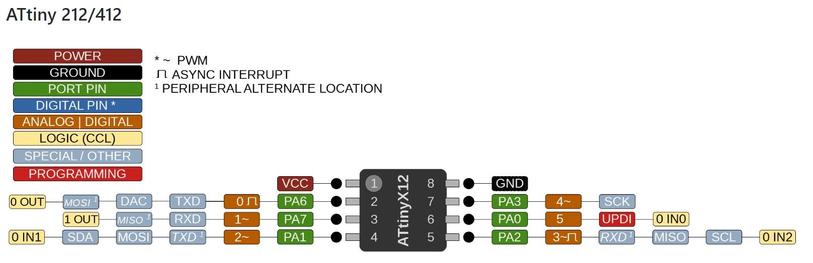
There is really a lot of information in the datasheet. Too much for a beginner like me to actually get into unless I know what I’m looking for. The pinout is very important and nice color-coded pinout diagrams for many processors including the ATtiny family. I also found the image from github.
● Programing my board
I made the ATTINY 412 board in Electronic Design week.
Also I made UPDI (Unified Program and Debug Interface) in Electronics production.
UPDI–The Unified Program and Debug Interface Physical Interface (UPDI PHY) provides programming and debugging through a 1-wire UART-based half-duplex interface using a single pin (either RESET or dedicated) for data reception and transmission. Communication through the UPDI is based on standard UART serial communication (Universal Synchronous and Asynchronous Receiver-Transmitter).
Communication lines of USART are:
Receiver - RX (PA1) and the Transmitter TX (PA2).
UPDI can access the entire I/O and data space of the device
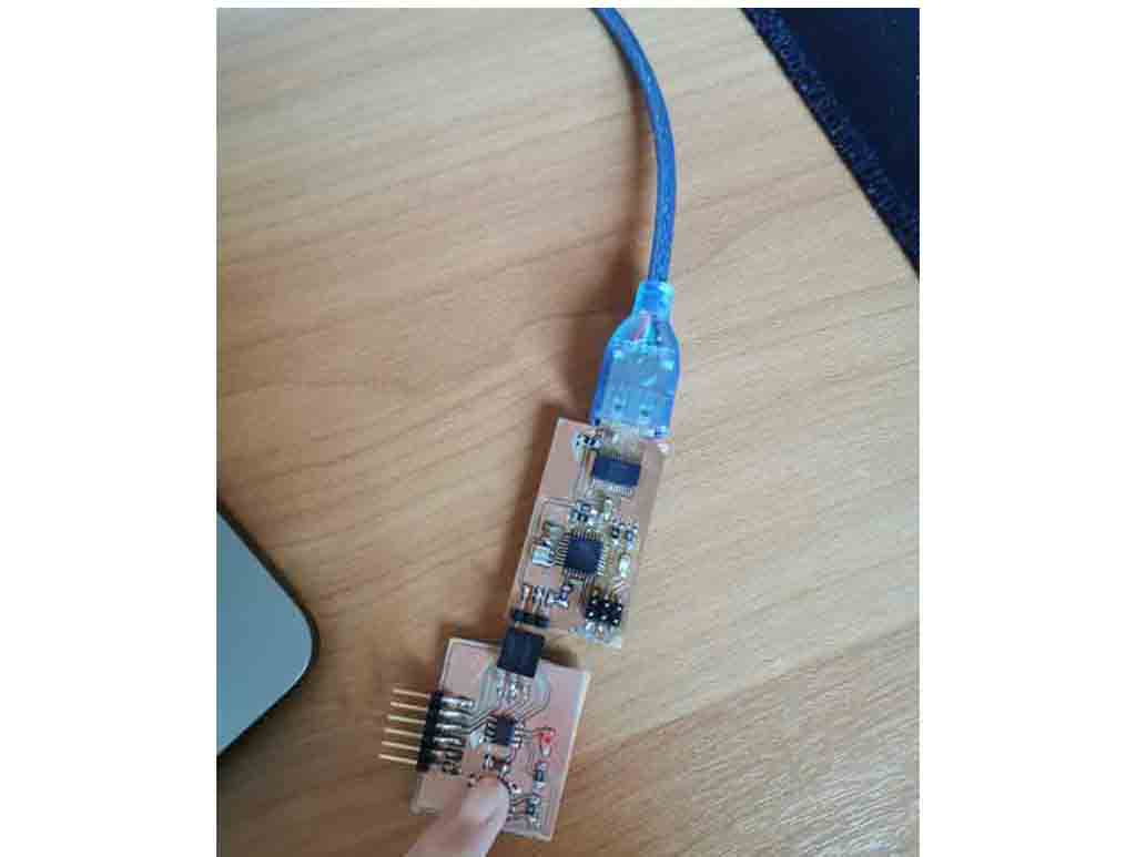
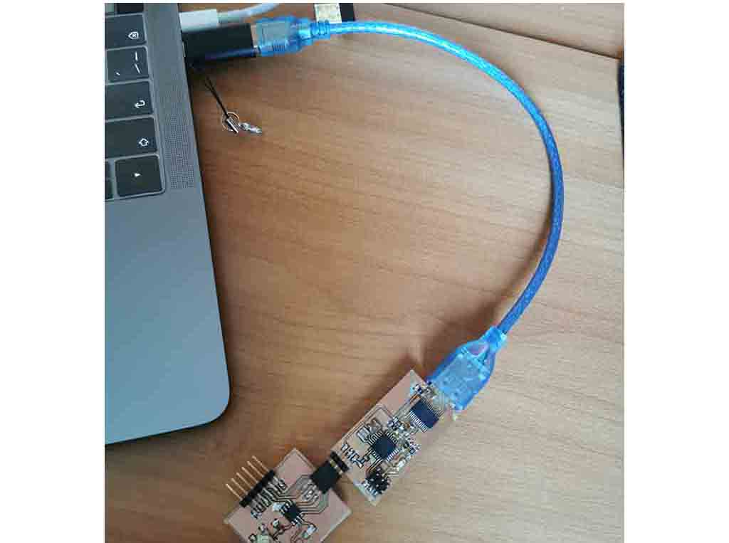
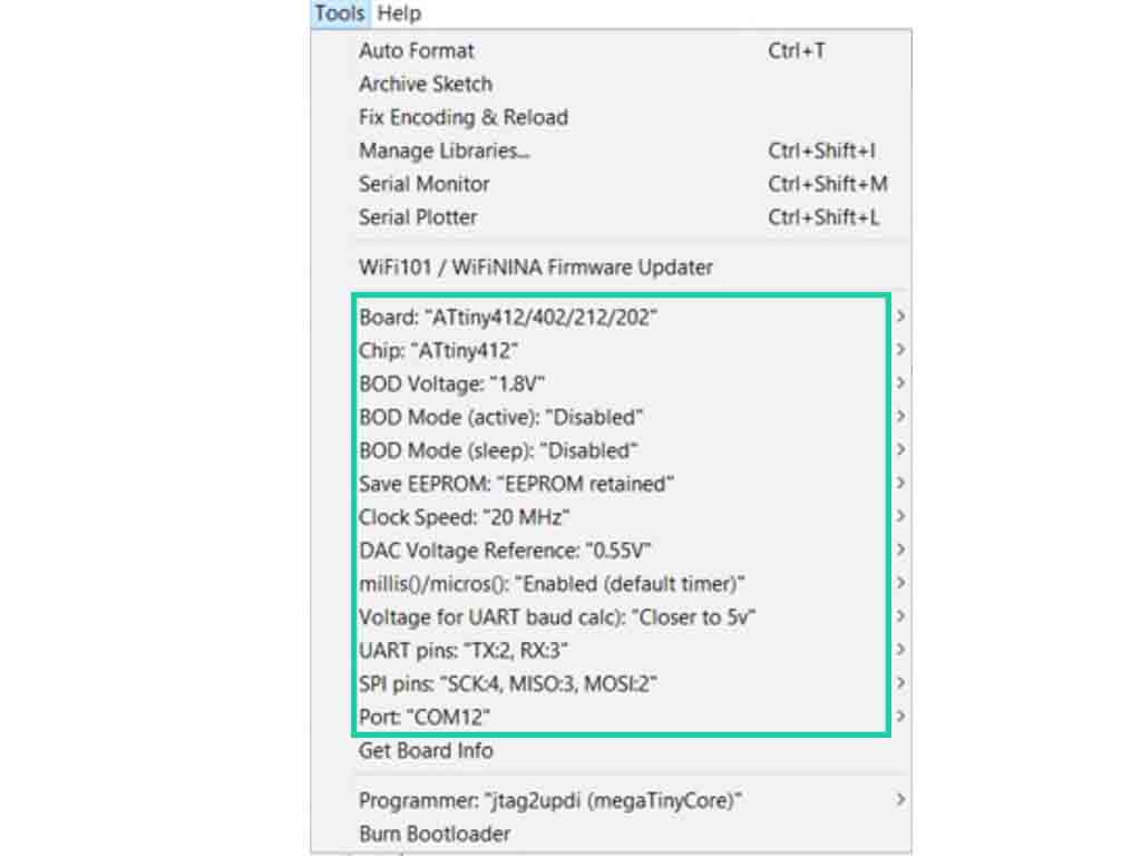
● I connected my previous microcontroller and programmer as shown in the image. Then I opened The Arduino IDE and in Tool settings I modified the settings to look as shown in the image below.
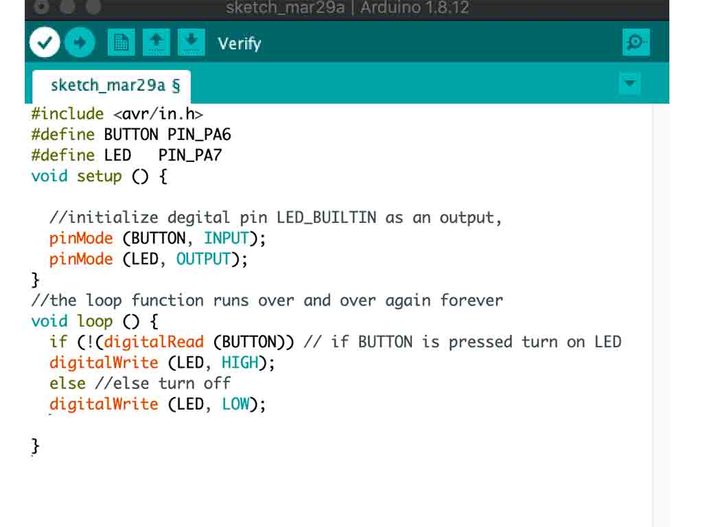
● The code I used are as below with help of Xinhui and Achille.
In order to write a program, I have to define a library containing ATtiny412 details, which is why the first line is #include and then the pin name to be configured. According to my schematic, the button is connected to pin PA6 and the LED is connected to pin PA7. Next I need to configure the button as input and LED as output. This explains the statement pinMode again. Note that when the button is pressed, it provides a way, so the pin button is logic “0” when it is pressed, otherwise it stops at the resistor. The logic is “1” when the button is not pressed. That’s why in my if statement, when the button is pressed, I put it! (Not) because the if statement is true, because! ‘0’ = ‘1’. The digitalread () statement is used to check the status of the pin digitalwrite () using write-on-pin. This is why when the button is clicked on the lead, not the click causes a continuous write program. I click on the upload program to load it into the ATtiny microcontroller.
#include <avr/io.h>
#define BUTTON PIN_PA6
#define LED   PIN_PA7
void setup() {

  // initialize digital pin LED_BUILTIN as an output.
pinMode(BUTTON, INPUT);
  pinMode(LED, OUTPUT);
}

// the loop function runs over and over again forever
void loop() {
  if(!(digitalRead(BUTTON))) //if BUTTON is pressed turn on LED
 digitalWrite(LED, HIGH);
 else  //else turn OFF
 digitalWrite(LED, LOW);

}
● The results when the button is pressed, the light is turned on.