2. Computer-Aided Design
Week’s Assignments
Assignment:
● This weeks assignment was to model (raster, vector, 2D, 3D, render, animate, simulate, …) a possible final project, and post it on your class page.
Learning Outcomes:
● Evaluate and select 2D and 3D software. ● Demonstrate processes used in modelling with 2D and 3D software
2D tool
I am a designer, so I familiar with the 2D software, such as Photoshop, Illustrator, InDesign. I was using my photos to do effects.
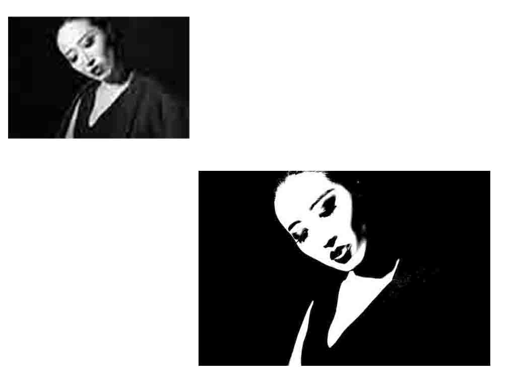
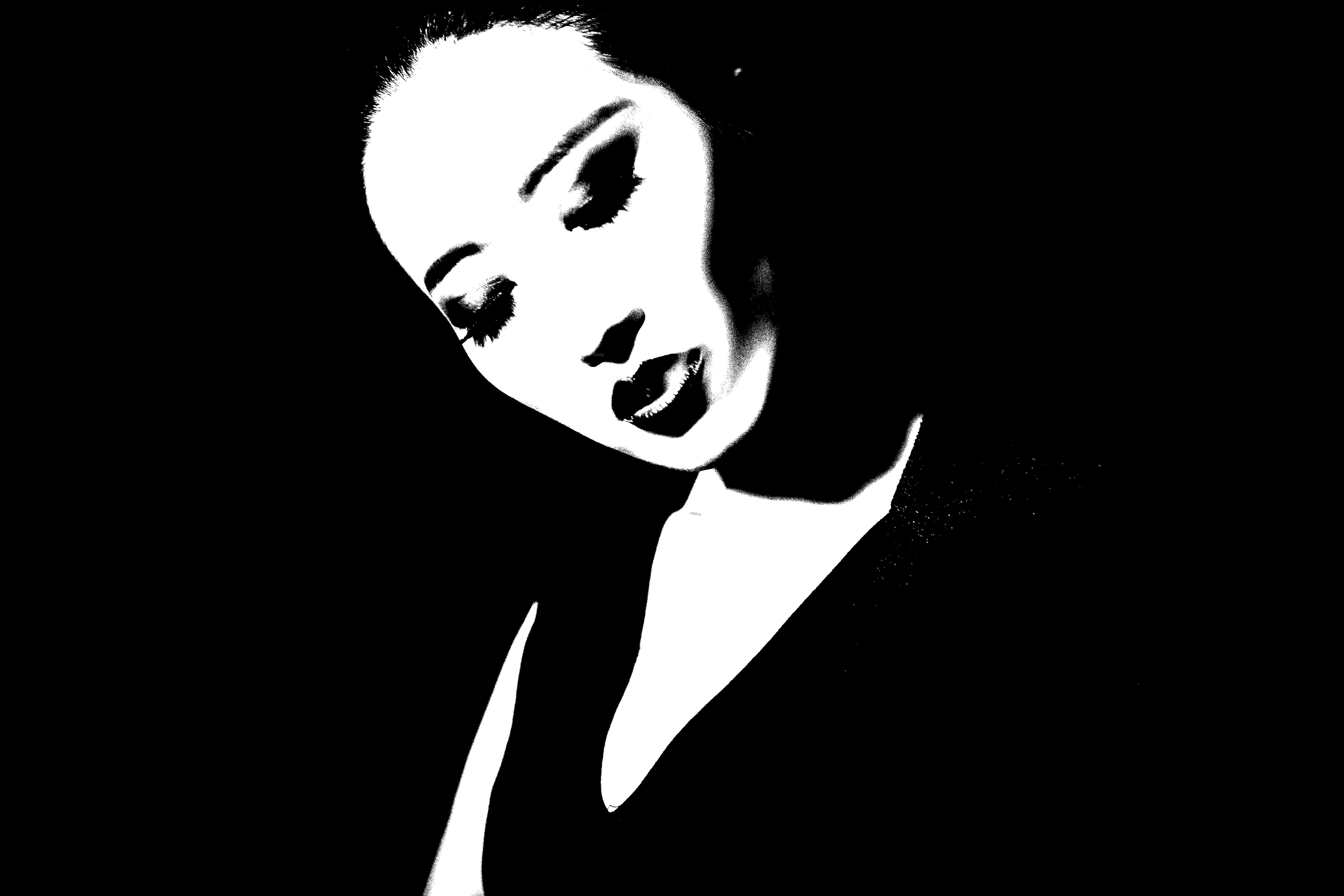
Silhouette effect
Step1. Ctrl+ N –create a new file
Step2. Open an image
Step3. Copy a layer
Step4. Using Threshold
Step5. Using selection tool to choose the part that you want to retain
Step6. Using eraser to delete the part that you do not want to retain
Step7. Ctrl + shift + S ----save as jpg
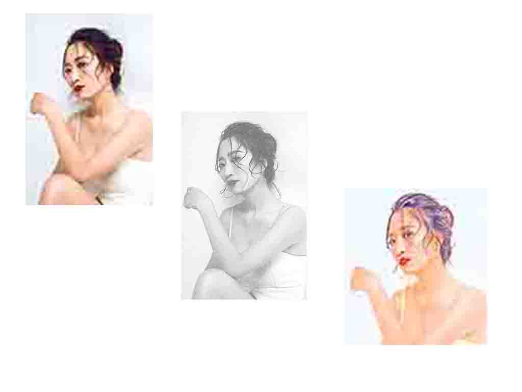
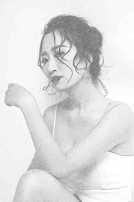
Sketch effect
Step1. Ctrl+ N –create a new file
Step2. Open an image
Step3. Copy a layer
Step4. Ctrl+ shift + U — to make the image without color
Step5. Ctrl + I ----to replace black to be white and replace white to be black
Step6. Using filter-Noise
Step7. Add a Mask
Step8. Using filter-Noise
Step9. Using Motion blur
Step10. Ctrl + shift + S ----save as jpg
I also recorded two videos to explain how to process images using Photoshop, but because the version of Photoshop is Chinese, and I cannot change it to be English, I am so sorry about this.
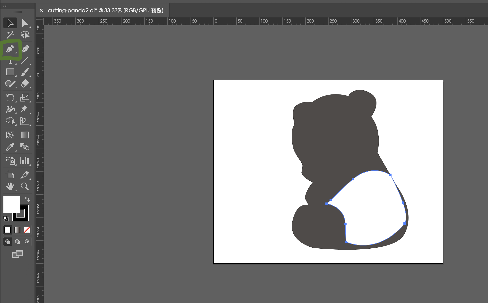
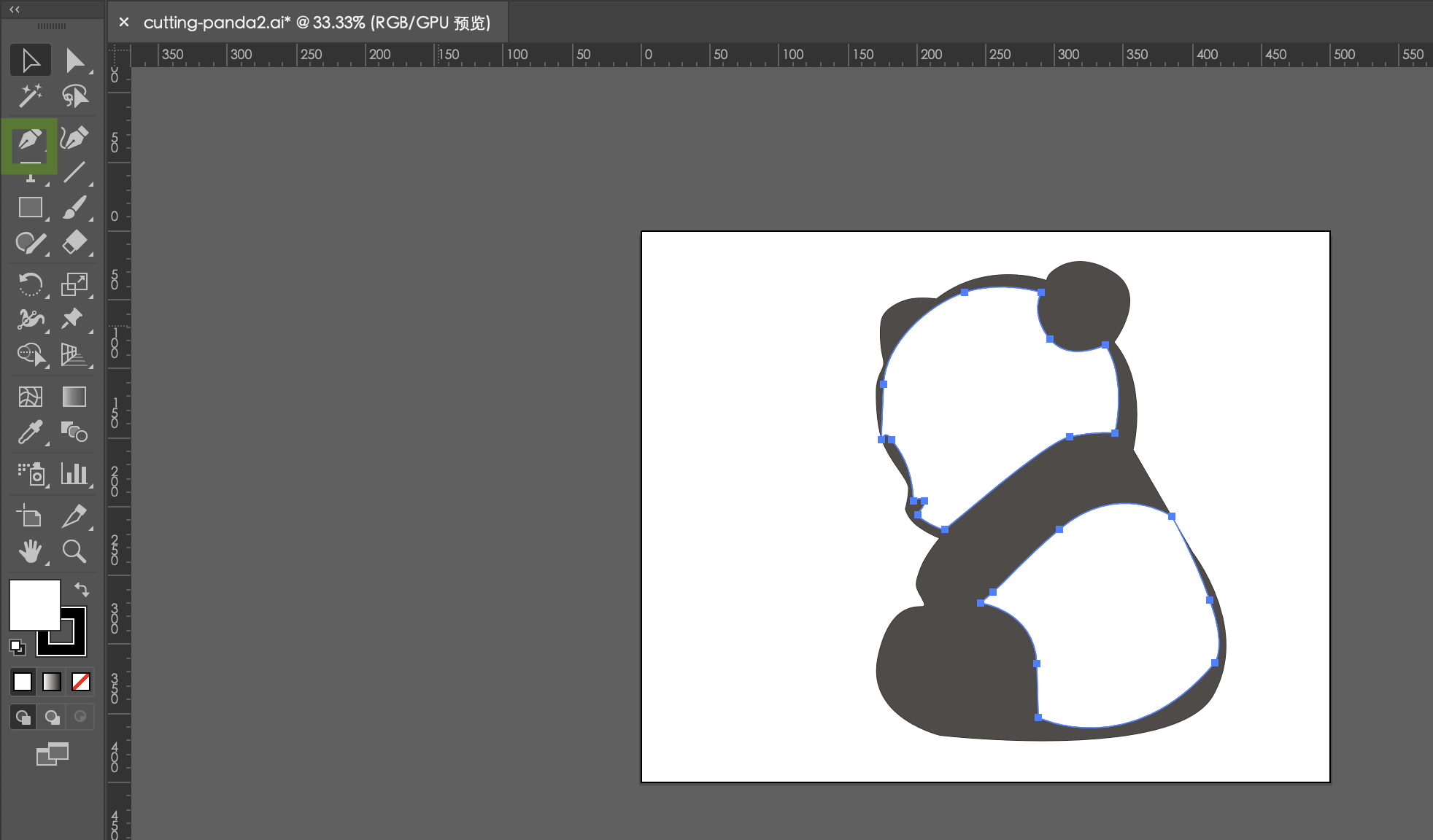
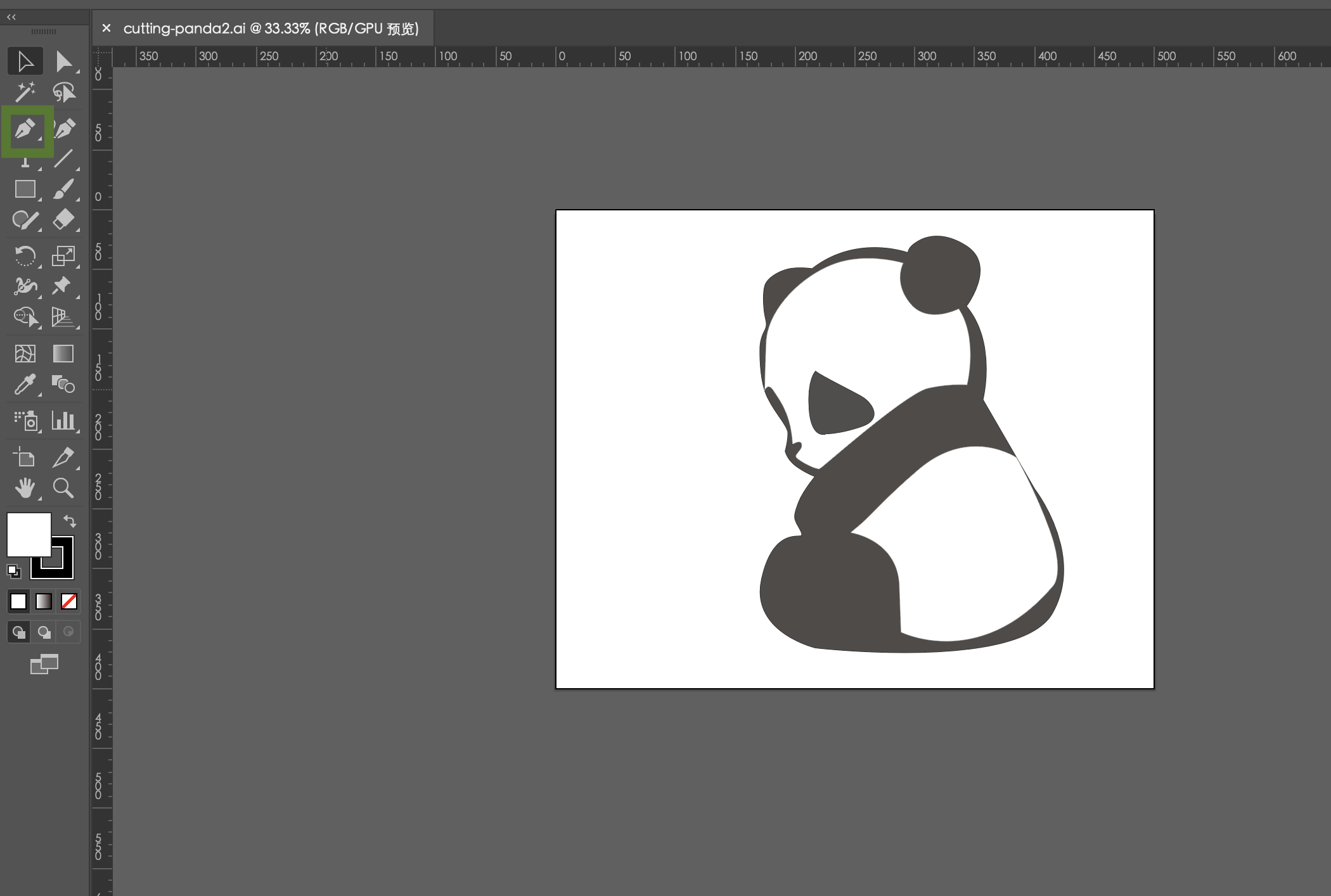
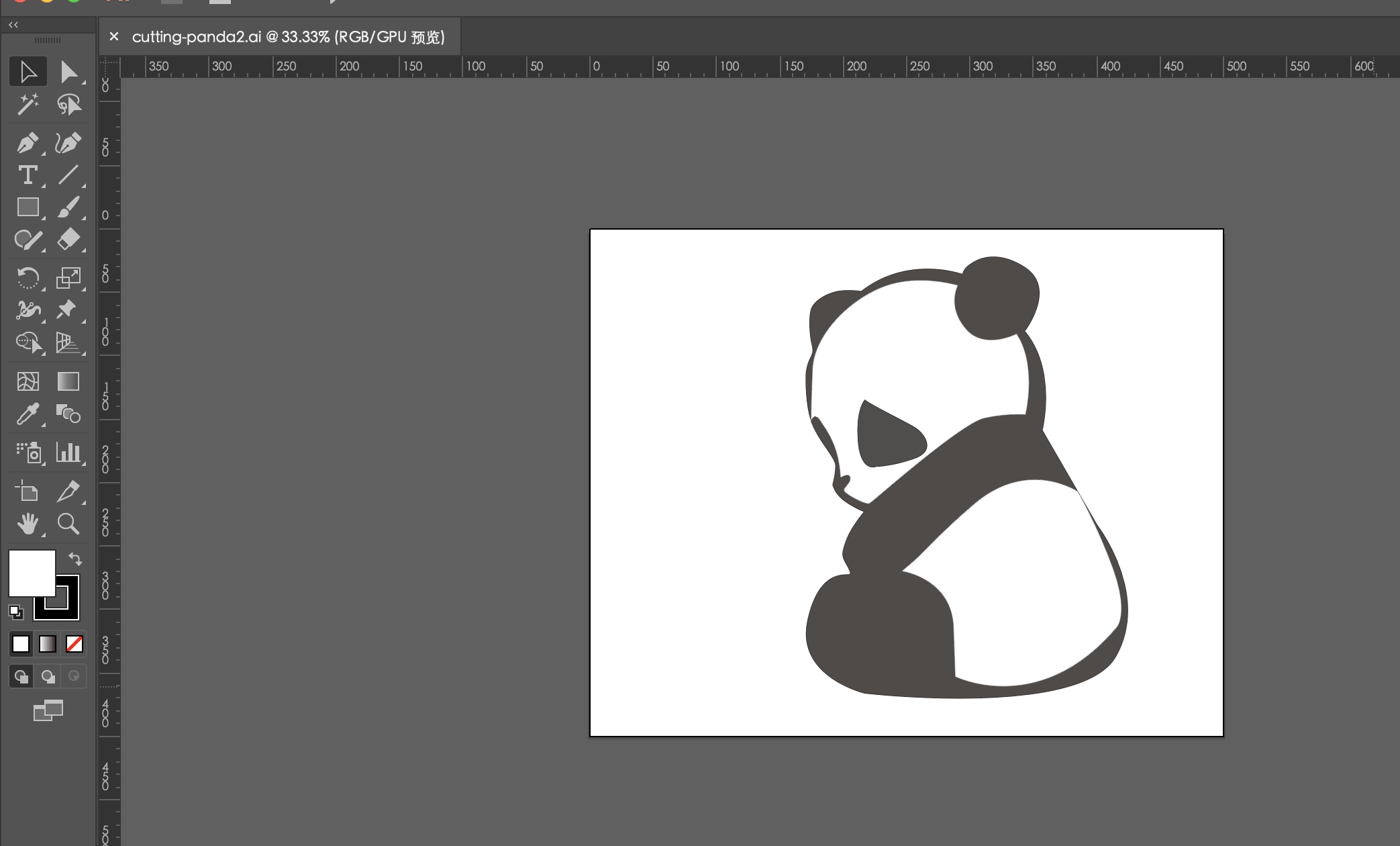
Also, I designed an image by Adobe-Illustrator for laser cutting, a panda with my name.
The main tool is pen in Adobe-Illustrator and set up the line and fill-in.
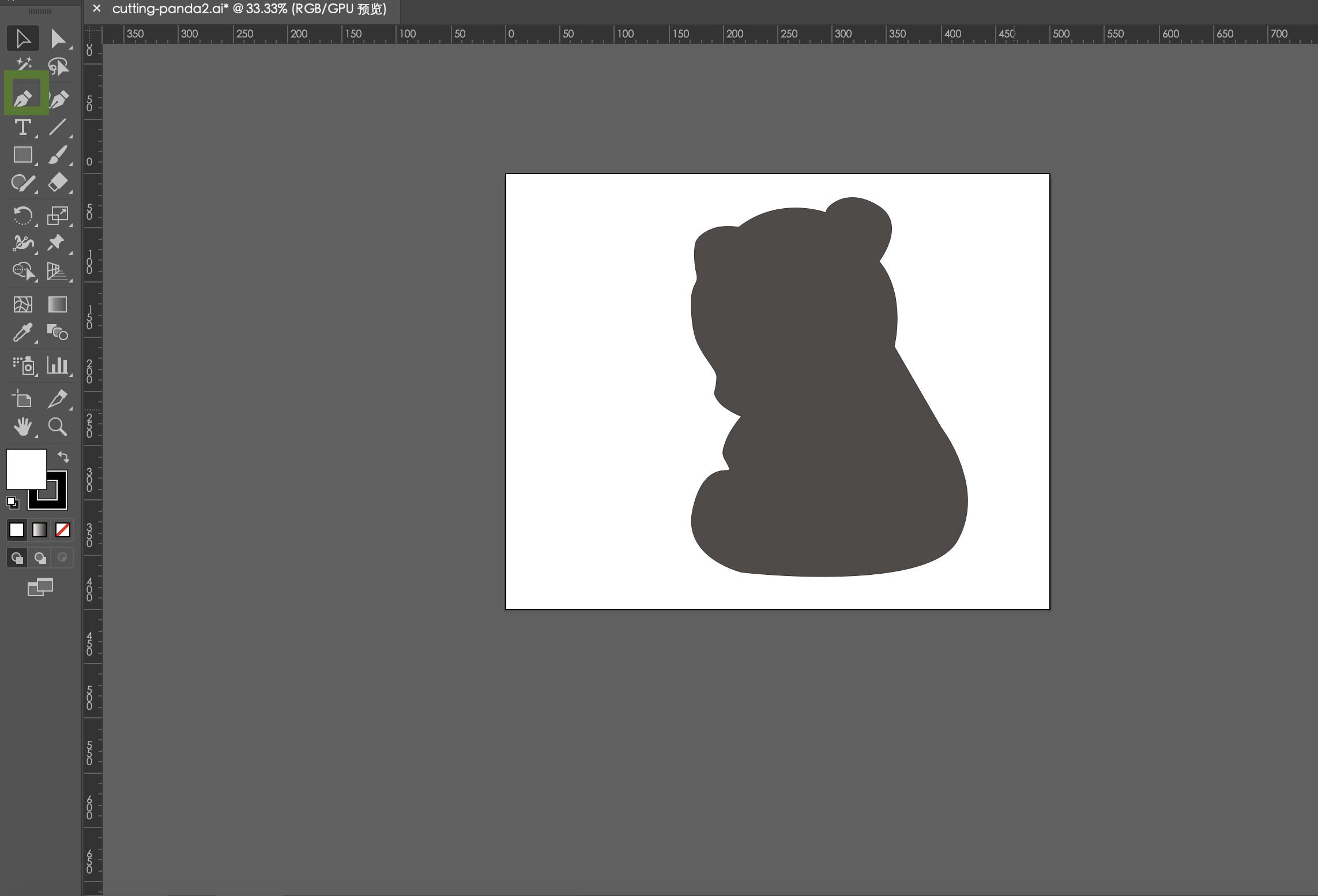
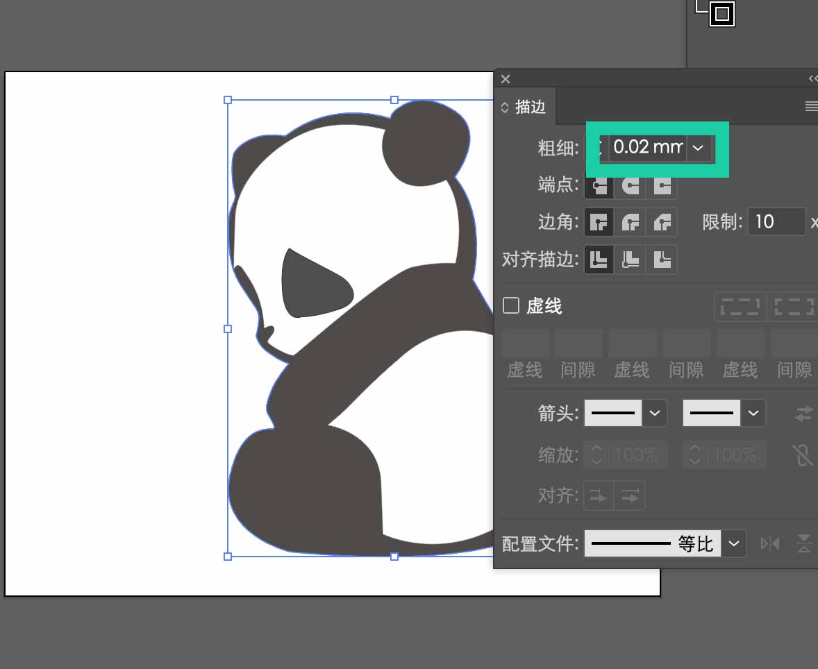
In the setting of the line, the number is 0.02mm, so the laser cutting machine and Vinyl cutter machine can recognize the edge to cut.
Also, the another method is to vectorize the image by Inkscape. Selecting Edit path by nodes from the left panel (or press F2), then clicking on the vectorized image and using shift+ctrl+F set up the fill, stoke paint, and stroke style with the width 0.200mm.
After these steps, I save it as pdf, so it can be used for laser cutting machine.
3D tool
Before this course, my tutor said I would be using the 3D tool and suggest me to learn Fusion 360, so I was starting to learn it for about two weeks. In this week, I do not meet difficult things, maybe because I prepared it before.
Following the tutorial online, I got a better understanding how to create a sketch, how to create a body, and so on.
I designed this object by following a Youtube Fusion360 tutorial.I saw it before in Action movies,which is really cool. Actually, I did not saw it before in my daily life.
Start a new design
Create a new Fusion design to get started. Click the Create menu then select Design.
Give your design a name and assign a project. Use projects to organize your designs and related data.
A new empty design is created and opened. This is your blank canvas to create anything you like. We’ll create some simple shapes to introduce you to the different types of geometry you can create.
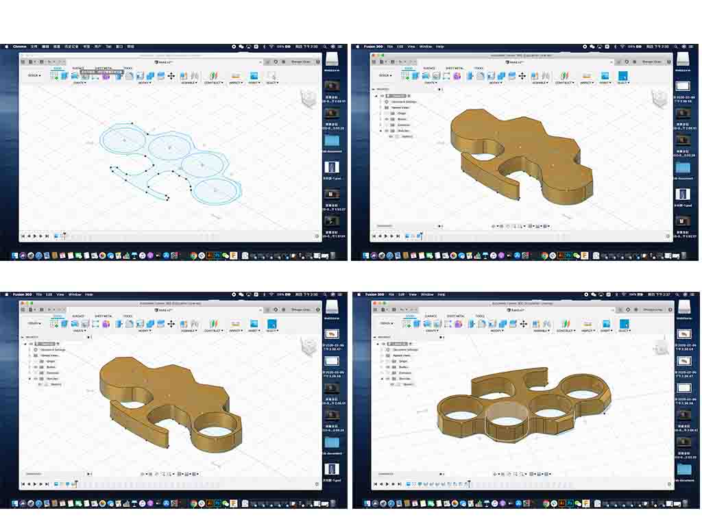
Use sketches to create bodies
For my case, I use 2D sketches to create bodies that are more complex than a simple cube or cylinder.
First, I click the fit point spline to create the outline, and use the 2 point circle to create the inside circle for the fingers.
Create basic bodies
I start in the Model workspace. Use the Model workspace to create prismatic shapes with straight faces and edges. There are basic shape commands in the Create menu (box, cylinder, sphere, and coil). Click on Box to begin creating a box. Select the bottom (XZ) plane then pick two points to define the corners of a rectangle. Specify a height by entering a value in the dialog box or by dragging the manipulator arrow. You can use the values shown in the dialog or use your own values. Click OK to complete the box.
For my case, the second step, I click the extrude to create the body, set the profile, start, direction, extent, distance >> 20.00mm, taper angle, and operation>> new body.
Third, as same as the second step, except the operation >>> cut, and the distance >>> -20.00mm.
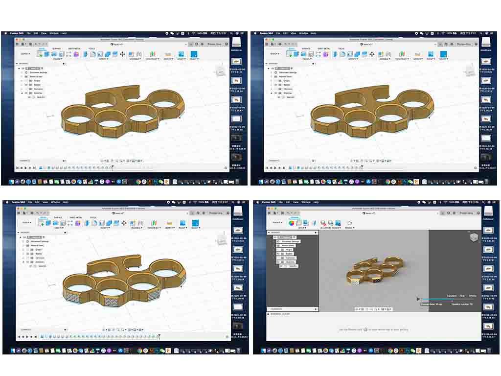
physical material
Physical Materials give appearances when applied, but only if no Appearances are present. This is because Appearances override the look of a part, much like spray paint overrides the look of a part in the real world.
So at first you might see the look of a physical material on your model, but as soon as you apply an appearance, the only way to see the physical materials is to open the dialog. Fusion will show you all physical materials at this time to make it easier to apply materials in large assemblies.
For my case, the fourth step, is to add the physical material. I click the modify >>> physical material, and choose the metal material, that more suitable for my design.
render
Step 1: Navigate to the Render Design Space.In the top-left of the design window, I find the workspaces button. Click it, and choose the “Render” environment.
Step 2: Work Left-To-Right. The toolbar at the top has two menus, one for setup, and one for rendering. Start from the left and work your way over. First up is appearances. Click the colored ball at the left of the toolbar, or open the Setup menu and choose “appearances.”
Step 3: Add Appearance. I can apply appearances to an entire body, or individual faces.
Start by selecting a materials folder - in this case, I want a brushed aluminum, so I click on the “metals” folder.
Scroll down to find the material you want wishing the folder. Then, click and drag it to the corresponding part of the model.
Step 4: Edit Swatch & Exit Appearance Panel. When I want to edit an appearance, just double-click on it in the “In this Design” panel.
I can edit the scale, rotation and roughness of the material, or click “advanced” for a whole new world of customization (including uploading your own image for the pattern) - but I’ll let you play with that if you’re so inclined. Click the “close” button in the appearance panel to leave the tool.
Step 5: Setup the Scene. right on the tool bar - click the lamp button, “Scene Settings” to setup the environment. First, scroll through and explore Fusion’s preset environment - they’re all very different and are great for different use cases. My go-to reliably-good-looking choice is “Soft Light.” I can change where the light is coming from, how bright the model is, what the ground is like (reflection or no?), or what the background color is. And be sure to check out the camera tools, I can change the perspective, and even pick a focal point for some nice depth-of-field rendering.
Step 6: RAY TRACE! And save an image. The Ray Tracing panel will show you the number of iterations the image has gone through, as well as the number of seconds. Once you’re happy with the quality, just click the Save button on the toolbar!
I hope in the next weeks, and I can print these images and the 3D design. I am expecting to do this.