Trouble Shooting Log
In this section, I summarized the questions and problems I personally encountered as a log for potential references.
Q: Is Weasley clock a feasible goal?
A: Yes. Several success projects have been proposed before.
- Build Your Own "Weasley" Location Clock! (Raspberry Pi/ GWS Servos)
- A simpler Version (Arduino MKR1000/ Sail Winch Servo)
- LED Version(Partico Photon/LED)
On thing to concern is that the FabAcademy project requires self-designed boards, so the tutorials cannot help all the way through.
Q: How to choose between LED vs Clock version?
A: Both strategies are feasible. The LED version is easier for indicating the location of multiple devices, which may better fulfill the original version described in Harry Potter story. The problem is that it is harder to design the clock face and the clock will be less similar to the original version. On the other hand, the clock version is easier to design but how to control multiple clock hands remains to be a question. It is possible to support tracking multiple devices, presumably with a multi-layer axis, but it is definitely too complex for this project and out of the scope. Eta clock has done this before and may be a reference.
Because I chose the clock version, the rest of the log are all about the clock version.
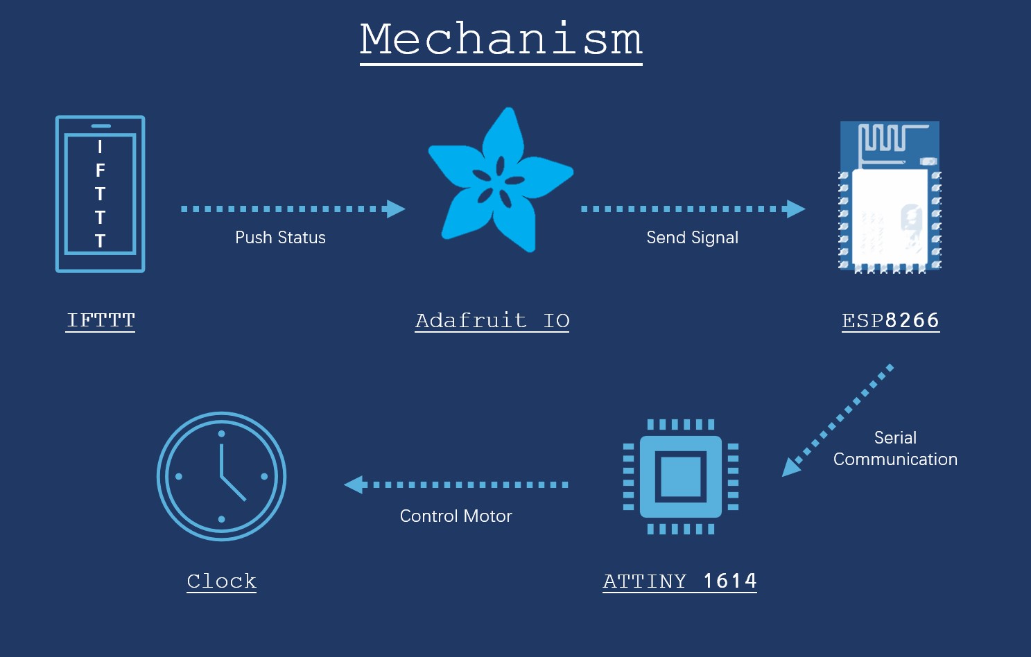
Q: What is the mechanism underlying the Clock version strategy?
A: The major mechanism is similar to other projects:Mobile device push signal-> Clock receive and process the signal -> Indicate location
However, the tutorials all used dev boards, which have their own modules on IFTTT or even their own APPs, which will not be helpful for this project.
Fortunately, our instructor Ivan invented a better way. Instead of using the dev boards modules on IFTTT, the Adafruit module and Adafruit dashboard can bridge the self-made board and the mobile device.
Q: What chips should be used for this project
A: ESP8266 for device connection and ATtiny 1614 for signal processing and motor control.
Q: What type of motor should be used for this project?
A: It depends on the clock shape.
If the clock is half of a circle, a normal servo motor will be ideal. The servo motor can be set to any angle between 0° to 180° using the servo.write() arduino command, which is ideal for this purpose.
If the clock is a full circle, a stepper motor or a Sail Winch Servo should be used. In fact, the Sail Winch Servo may be a better choice if it is available because it can pinpoint a position within the 720° range. The problem is that it is not that normal and needs to be ordered separately.
Because the Sail Winch servo I ordered online never arrives, I used a stepper servo motor.
* The 360° servo motor will not turn to a specific position and stop like a normal 180 degree servo, Sail Winch servo will.
Q: How should be boards to be designed.
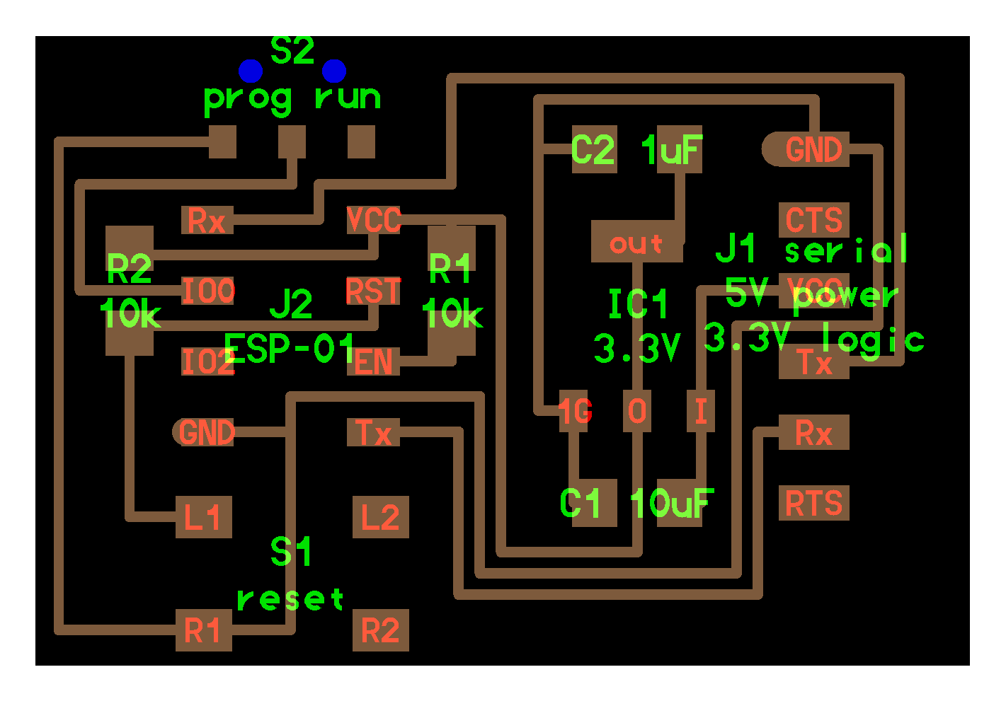
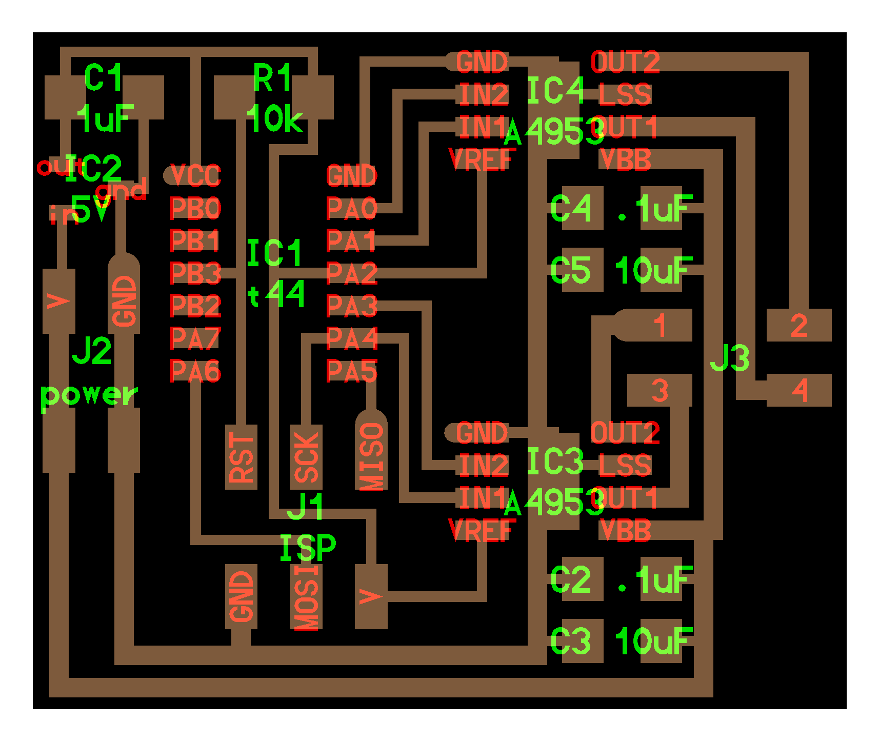
A: The board I used are based on Neil's example.
ESP8266: Week 14 Networking and Communications -> ESP8266-01
ATtiny 1614:Output Devices -> stepper motor(bipolar) 44
Because I did not have much knowledge about the circuits, I modified the boards with the suggestions of our instructors. If you are in the same status, please turn to your instructors for help.
Q: How to determine the coil-lead map of the stepper motor
A: The motor I used has a tricky problem as its datasheet provide confusing information about its coil color code. The problem is that there are multiple combinations that can lead the motor to rotate clockwise. The way I used to determine the coil color is to first let the motor to rotate clockwise with a huge delay, like 10 seconds. For each step it moves, I used the oscilloscope to test the voltage of each lead. In this way, the activation sequence can be determined.
Q: What are the problems I encountered when running the program for ESP8266?
A: The code can be found on the Embedded Programming section on the final project system.
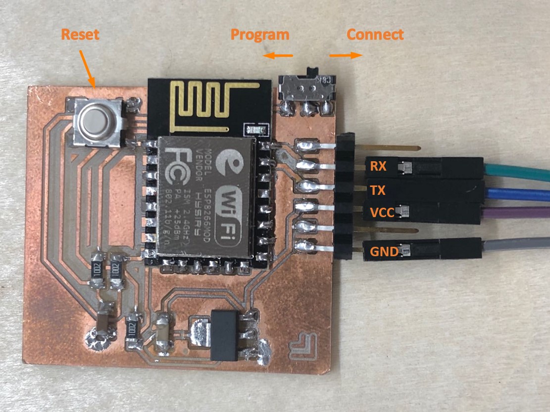
The major problem I met is that the ESP8266 module has two modes: connection and programming. But it is not very clear which side is for connection. In my case, in the first several attempts, I reversed the two modes and hence cannot connect.
The right step is to first switch to the program mode and upload the code. After the uploading is done, turn the switch to the connection mode and ESP8266 chip will start to connect to the SSID set in the code automatically.
I personally think use the Hotspot WiFi from the phone, so it is easier to determine the connection status.
Besides this issue, the code of ESP8266 runs smooth.
Q: What are the problems I encountered when running the program for ATtiny 1614
A: The code can be found on the Embedded Programming section on the final project system.
This code contains three major sections:
-stepMotor(int step) function that defines the activation sequence of the motor coils
-step(int steps_to_move) function that defines the algorithm of the motor to move between positions. A maximum step, which is the number of steps for a full revolution, is used as the reference to control the moving direction of the motor.
-moveToLocation(int location) function that gets the serial print from the serial input and determines the steps to go.
1. Determine the activation sequence of the motor coil is a tricky issue in my case, because the datasheet is confusing. As mentioned above, in order to determine the right sequence, measureing the voltage with the oscilloscope will be a good idea.
2. The step length is not correct at first. While the datasheet says that the step length is 7.5°, which should make 48 steps for a full rotation, the motor turns 52 steps per revolution (but 26 steps are more than half of the circle). Lastly, it seems there is a command placed in the wrong layer in the Arduino code, while the connection between the clock hand and the clock axis is also a little bit loose.
3. Serial port communication is also an issue. I originally use the serial.print() to send the amount of steps; however, this Arduino command often send data in the ASCII format. Moreover, when I test with number 0, it is exactly 48, which is also the totally steps for a full revolution. It took me some time to realize that it is not a problem of algorithm, but a problem of data format. So I used the following method to transform the data into integers.
              //for location10, 11 and 12, which are more than 1 byte

              while (Serial.available()>0) {

               int inChar = Serial.read();

                if (isDigit(inChar)) {

                  // convert the incoming byte to a char and add it to the string:

                  inString += (char)inChar;

                }

                // if you get a newline, print the string, then the string's value:

                if (inChar == '\n') {

                  //Serial.print("Value:");

                  int location = inString.toInt();

                  //Serial.println(location);

                  //Serial.print("String: ");

                  //Serial.println(inString);

                  // clear the string for new input:


                  inString = "";//


                  Serial.print("location: ");

                  Serial.println(location);

                  moveToLocation(location);
                  //step(location);

               }

               }
These are roughly the major problems I encountered in this process.