6. 3D Scanning and printing
Group assignment:
- Test the design rules for your 3D printer(s)
Individual assignment:
-
Design and 3D print an object (small, few cm3, limited by printer time) that could not be made subtractively
-
3D scan an object (and optionally print it)
Group assignment
Why we need to test the design rules for different 3D printers
The main reason for testing the design rules for different 3D printers is that these printers have different capabilities. They may use different materials, adopt different algorithms, and have different strategies in dealing with complex structures. Thus, it is necessary to acquire this knowledge in order to choose the most appropriate 3D printers for work.
3D printers used for testing the design rules
Our group ( Tatiana Avsievich, Xinhui Hu, Yazan Barhoush and Zhengya Gong ) used three different 3D printers for this test.
Stratasys Fortus 380mc
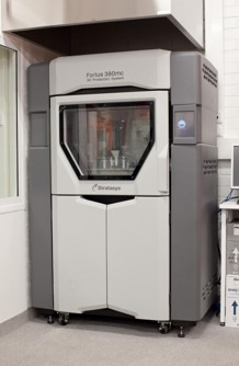
This machine can work overnight and run automatically without supervision, which makes it the best choice for printing objects with complex structure.
Sindoh 3DWOX DP200
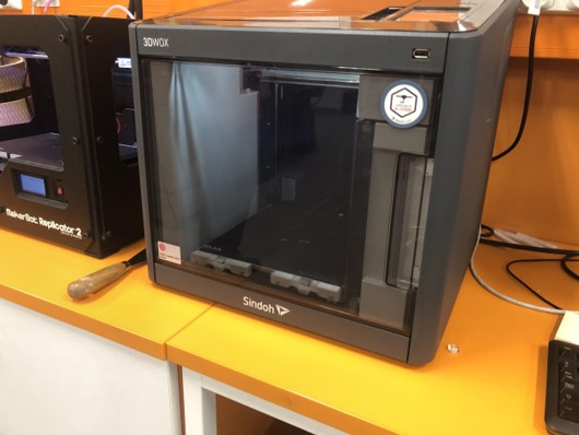
Sindoh is the only machine that allows the printing work to be paused and resumed.
MakerBot Replicator 2
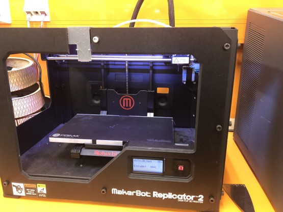
The MakerBot has the fastest speed in printing among these three machines.
3D printing process and materials we used
All three 3D printers follow a straightforward workflow when printing: import files >> adjust and slice >> print. Stratasys Fortus 380mc used ABS for printing, while Sindoh and MakerBot used PLA.
ABS is the abbreviation for Acrylonitrile butadiene styrene, an oil-based plastic, which has a better performance in material strength, ductility, and thermal stability. PLA is the abbreviation of Polylactic acid, which is a starch-based plastic, and can be made from next to anything like rice, wheat, potatoes, and so on. PLA has a lower printing temperature and is easier to print. Hence, PLA is often used for printing fine parts or for aesthetical designs.
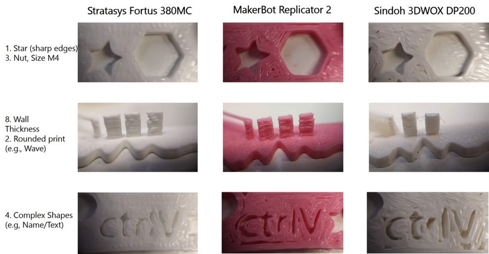
The design rules for 3D printers
We tested the design rules for 3D printers. However, we did not use the test files available on the FabAcademy website. Instead, we used a test file that was recommended by the staff at FabLab Oulu. The test file is available at Thingiverse.
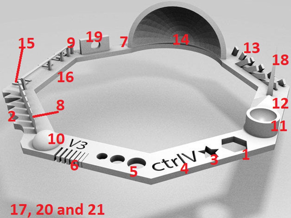
The file includes 21 tests. These cover all tests available on the FabAcademy, except for the infill test.
- Nut, Size M4 (e.g., the Nut should fit perfectly)
- Rounded print (e.g., Wave)
- Sharp Edges (e.g., Star)
- Complex Shapes (e.g, Name/Text)
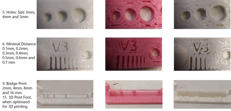
- Holes: Size 3mm, 4mm and 5mm
- Minimal Distance: 0.1mm, 0.2mm, 0.3mm, 0.4mm, 0.5mm, 0.6mm and 0.7 mm
- Height: 0.1mm, 0.2mm, 0.3mm, 0.4mm, 0.5mm, 0.6mm, 0.7mm, 0.8mm, 0.9mm, 1.0mm and 1.1 mm
- Wall Thickness: 0.1mm, 0.2mm, 0.3mm, 0.4mm, 0.5mm, 0.6mm and 0.7 mm
- Bridge Print: 2mm, 4mm, 8mm and 16 mm
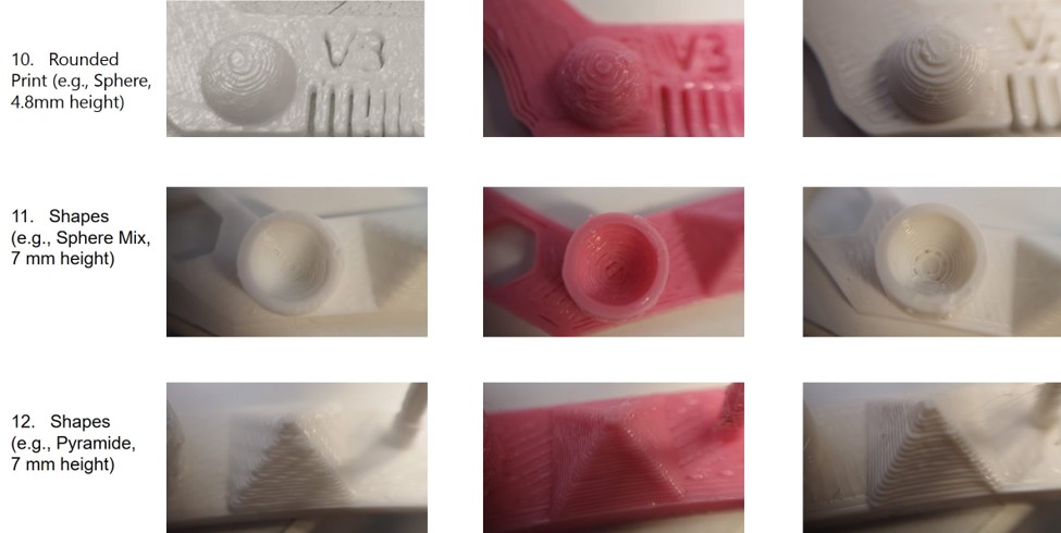
- Rounded Print (e.g., Sphere, 4.8mm height)
- Shapes (e.g., Sphere Mix, 7 mm height)
- Shapes (e.g., Pyramide, 7 mm height)
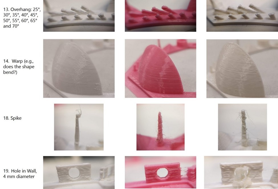
- Overhang: 25°, 30°, 35°, 40°, 45°, 50°, 55°, 60°, 65° and 70°
- Warp (e.g., does the shape bend?)
- 3D Print Font, when optimized for 3D printing
- Surface, Flatness
- Size of the model, 100 x 100mm x 23.83 (10mm width)
- Spike, minimum Layer Time, 21 mm height from Bottom (include Baseplate)
- Hole in Wall, 4 mm diameter
- Raft Test (e.g., raft should be just under the model)
- Retract Travel (e.g., check retract settings for longer travel)
The following figure shows the model in the test file (all-in-one), where it highlights the numbers of each of the 21 previously listed tests.
-
Sindoh 3DWOX DP200 provided the poorest quality among all three 3D printers.
-
According to a wall thickness test printers are not able to print walls less than 0.5 mm, and less than 0.6 mm for Sindoh 3DWOX DP200.
-
MakerBot Replicator 2 has achieved the best resolution in minimal distance test, however separate lines are not straight. Stratasys Fortus 380MC demonstrated the worst result.
-
All printers gave a good result for the bridging test.
-
Rounded prints (sphere height and mix) were the best for Stratasys Fortus 380MC, while prints made Sindoh 3DWOX DP200 looked rough with visible layers.
-
Overhangs came out satisfactory with all the printers, except the shape of hangs, which has changed for Stratasys Fortus 380MC, many strings observed for Sindoh 3DWOX DP200, and the best result was made with MakerBot Replicator 2.
-
Spikes were printed of full height, however with too many strings of material around.
Individual assignment
3D modelling
I decided to make a small hinged box. I watched a couple of YouTube videos to get an idea of how to design a hinged box and how to use joints in Fusion 360. I found this video and used it as a guideline to design my box.
Step 1
I created a center rectangle sketch (Create Sketch, CREATE >> Rectangle >> Center Rectangle) and extruded (Extrude tool) it to cube. I defined parameters that I was going to use based on the parameters used in the YouTube video.
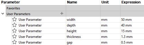
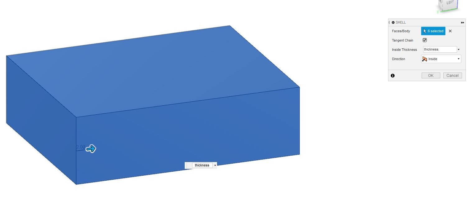
I used a shell tool (MODIFY >> Shell), selected the whole body and defined the Inside Thickness as thickness (parameter).
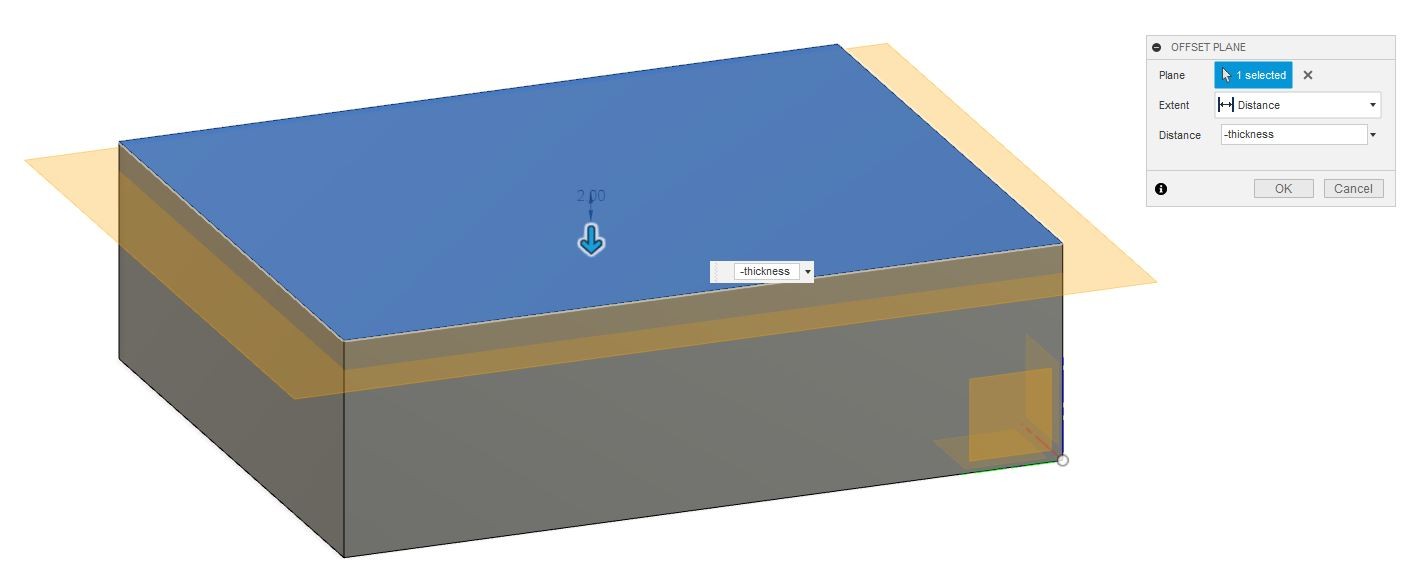
Step 2
To make a lid to the box I used an offset plane (CONSTRUCT >> Offset Plane) and set it to distance -thickness from the top of the box.
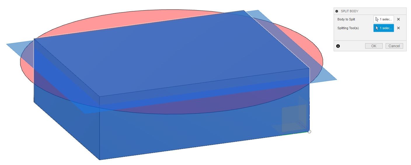
Next I used a split body tool (MODIFY >> Split Body) and chose box body as a body to split and the offset plane as a splitting tool.
Step 3
I created a new sketch to the shorter edge plane of the box.
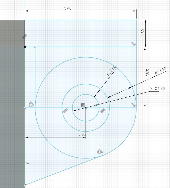
I created a 2.95 mm long (=gap+thickness+gap+thickness/2) line (CREATE >> line) from the box edge and used its end point as a ceterpoint of three center diameter circle (CREATE >> Center Diameter Circle). I defined the diameter of the inner circle using dimension tool (CREATE >> Sketch Dimension) as thickness, the distance between inner and middle circle perimeters as gap and the distance between middle and outer circle perimeters as thickness. I also cteated lines from the box edge to outer circle perimeter and from sides of the outer cirlce to the lid extension rectangle.
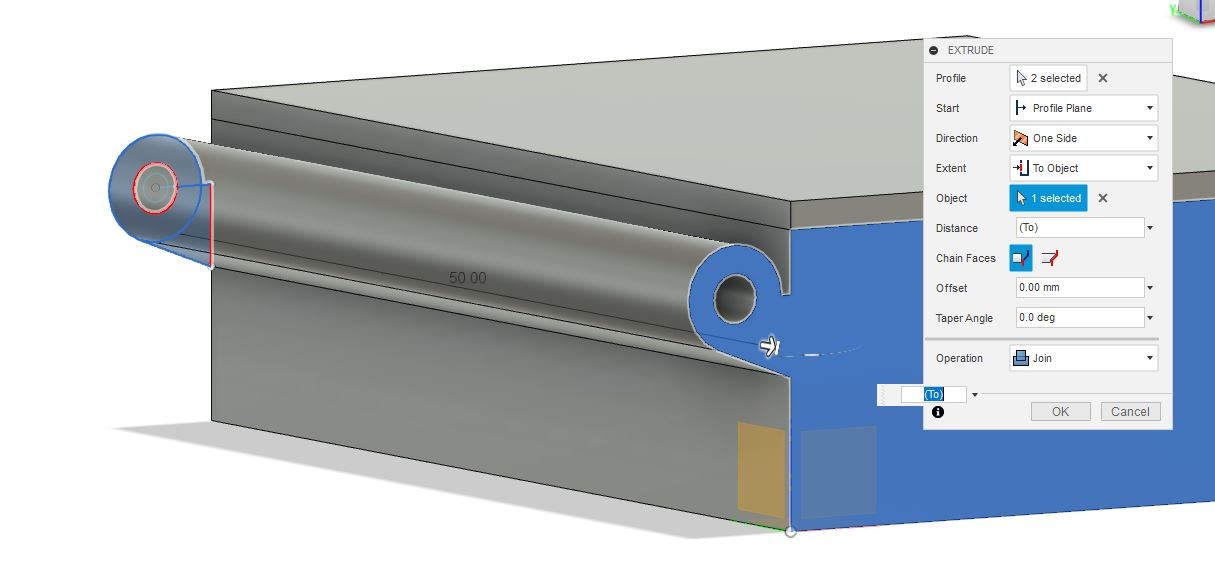
Step 4
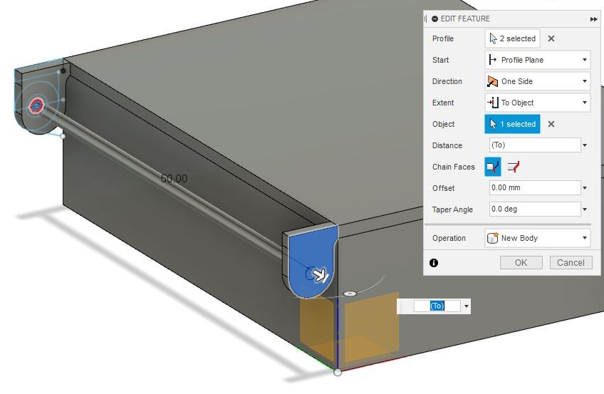
¨To make a bottom part of the hinge I chose from the sketch the part that connects outer cirlcle bottom left corner to the edge of the box and the part between outer and middle cirle and extruded it to opposite side on the box (Extent: To Object) and chose the Operation to be New Body (wrong in the picture).
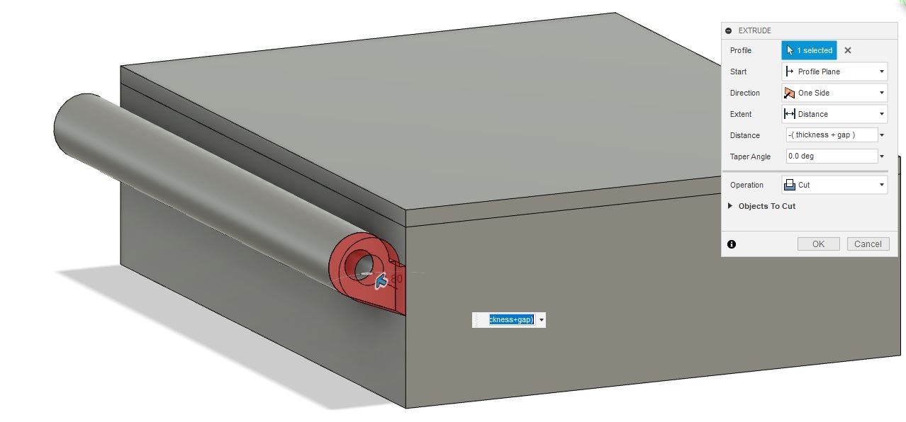
To make space for the top part of the hinge I extruded a cut (Distance: -(thickness + gap) from both ends of the bottom hinge part.
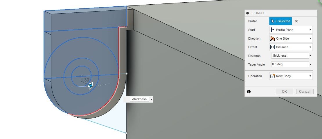
Step 5
To make a top part of the hinge I selected the parts shown in the next picture and extruded them to -thickness.
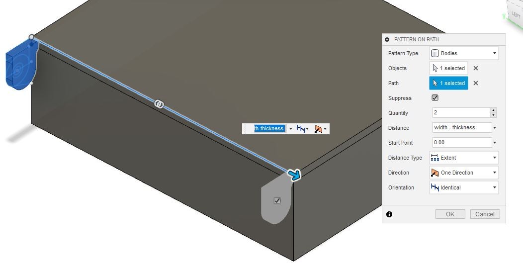
To make top part to both edges I used pattern tool (CREATE >> Pattern >> Pattern On Path) with Distance: width-thickness.
I also extruded the inner cirlce to the opposite side top hinge.
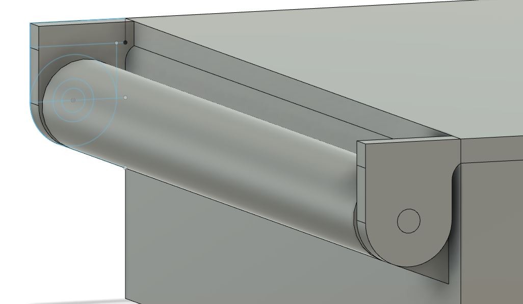
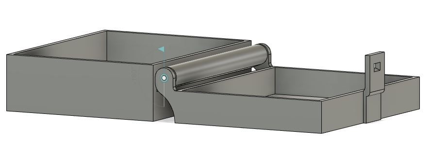
The final hinge
Step 6
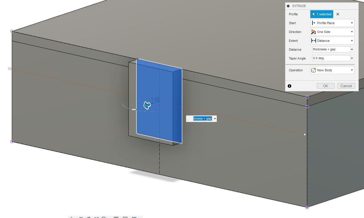
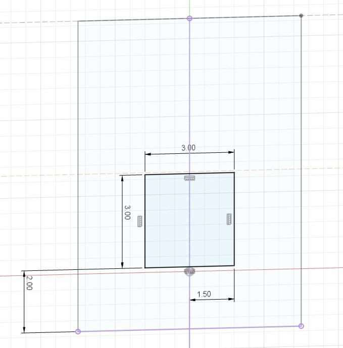
Next I created a snap joint to the opposite side of the box to keep the box closed. I created a rectangular 10x7.5mm sketch and extruded it to thickness+gap.
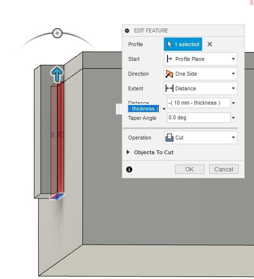
I created another sketch to the bottom of the snap joint and extruded a cut to -(10mm - thickness).
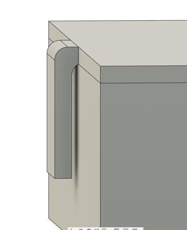
I used a fillet tool to round the edges shown in the picture.
Step 7
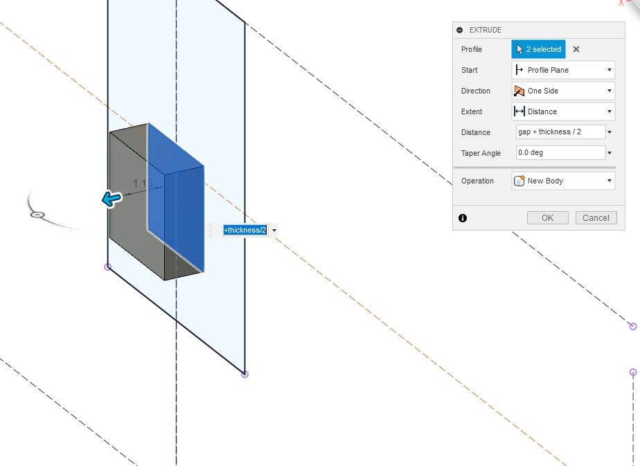
I created another rectangle to the sketch to make the other part of the snap joint.
I extruded it to Distance: gap + thickness/2.
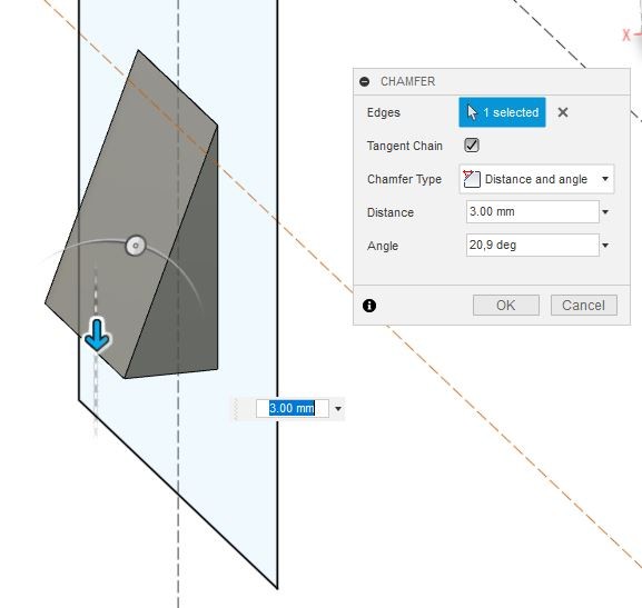
I used a chamfer tool (MODIFY >> Chamfer) with Chamfer Type: Distance and angle, Distance: 3 mm and Angle: 20.9 deg.
Step 8
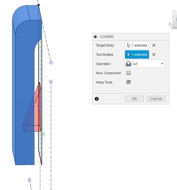
I used a combine tool (MODIFY >> Combine ) to make a slot for the inner part of the snap joint. I chose outer part to be Target Body and inner part to be Tool Body for the cut and chose Keep Tools.
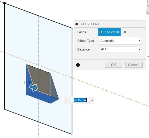
I made 0.15 mm spacing between joints with offset face tool (MODIFY >> Offset Face) by choosing the inner joint faces.
Step 9
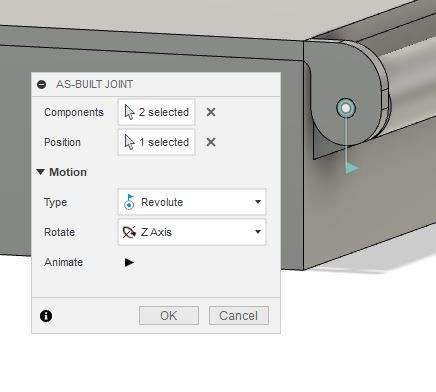
To make a joint to hinge I first made components from bodies and rearranged bodies under top and bottom parts of the box.
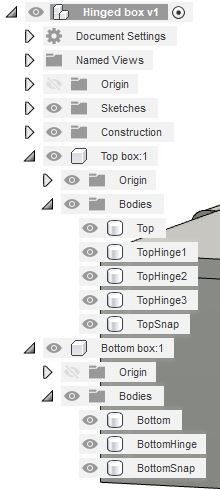
I made a joint (ASSEMBLE >> As-built Joint) and chose Components to be the top and bottom parts of the box, Position to be the inner cirlce of the hinge and Motion Type to be Revolute.
The lid spinned just the way I wanted it to do. I exported the model as stl file (File >> Export).
3D printing
Step 1
I opened the stl file in Cura. The printer used was one of our Mobile Fablab 3D printers (Monoprice MP Mini Delta).
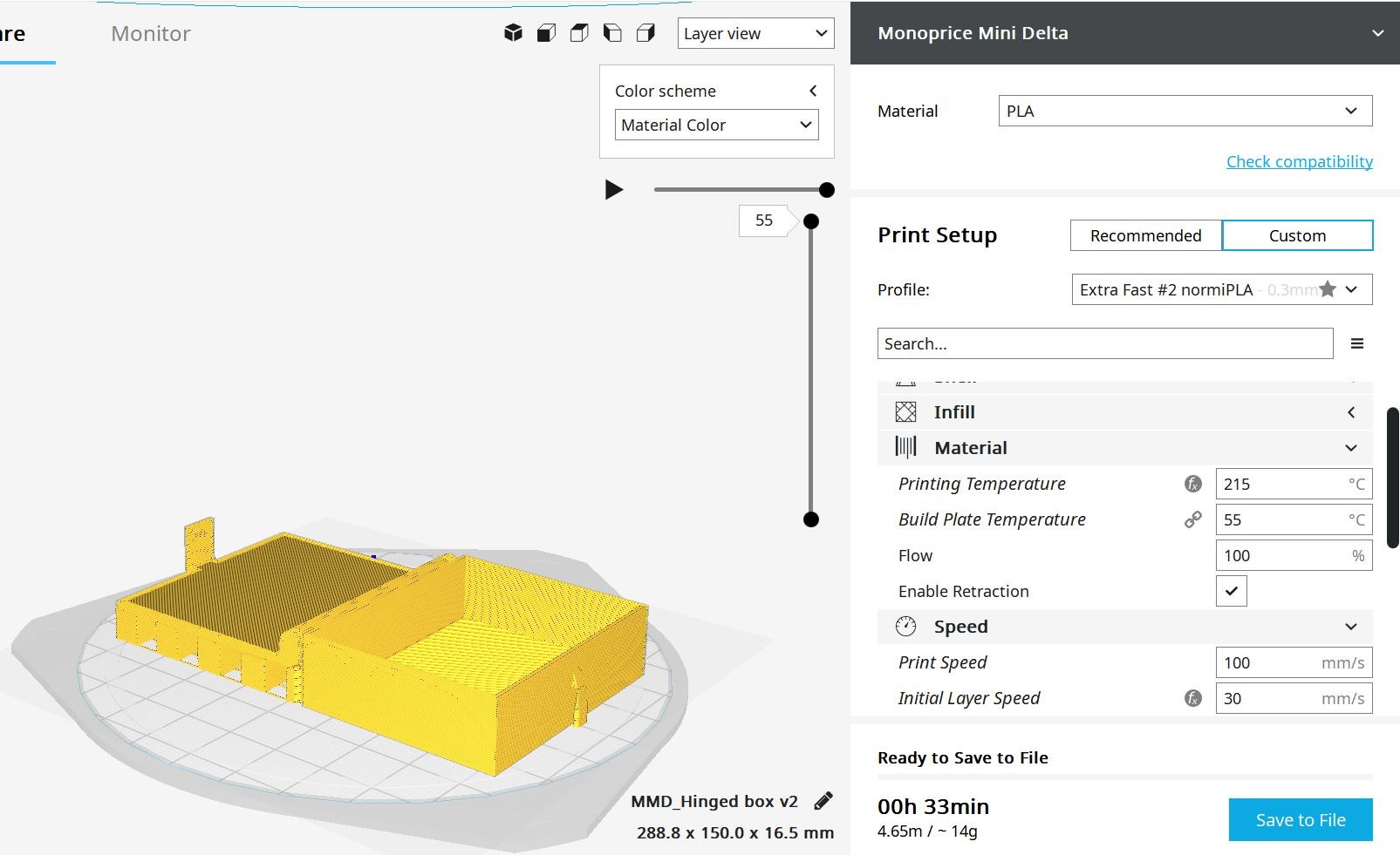
I printed two versions of the box; one with layer height 0.3 mm and one with 0.15 mm. Printing temperature was set to 215°C, build plate temperature to 55°C, Print Speed to 100 mm/s and initial layer speed to 30 mm/s. Infill Density was 20 % and Support Overhang Angle 50°. I saved the gcode files to my computer.
Step 2
We control our Mini Delta printers via OctoPrint. Every printer is connected to RaspberryPi and each one has its own IP adress. I opened a browser, typed printer’s IP adress, connected to the printer, uploaded the gcode file and pressed print.
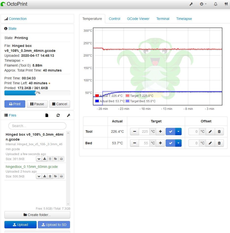
The printer usually makes nicer product with 0.3 mm layer height, but the hinge obviously worked better with 0.15 mm layer height print. Both prints were really fragile and they finally broke when testing the hinge.
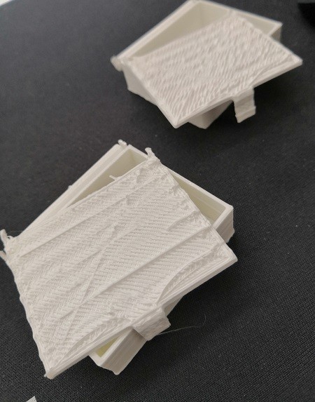
Step 3
I modified the model so that both lid and bottom part of the box touched the build plate (extruded the open box lid to bottom plane). I also modified the top hinge part with fillet tool to make it more robust.
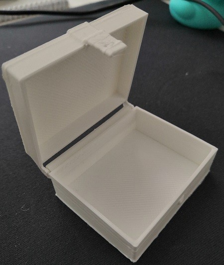
I scaled the box to 108 % in Cura to try if that would help to print the hinge part. I printed the second version the same way as the first versions but used print temperature of 225°C instead of 215°C.
This version printed out really nicely and the hinge part was working. Only part that should be modified is the snap joint.
3D scanning
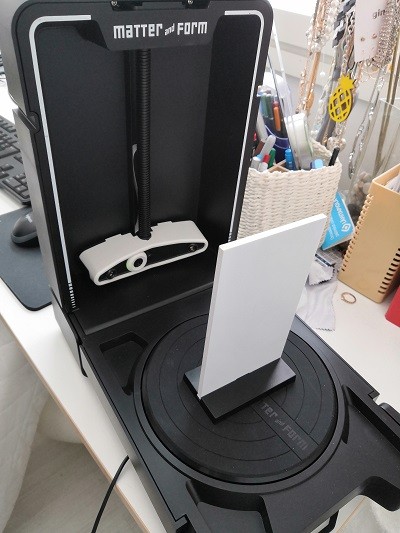
I used our Mobile Fablab 3D scanner. The scanner is Matter and Form V2 3D Scanner and the scanning software is MFStudio.
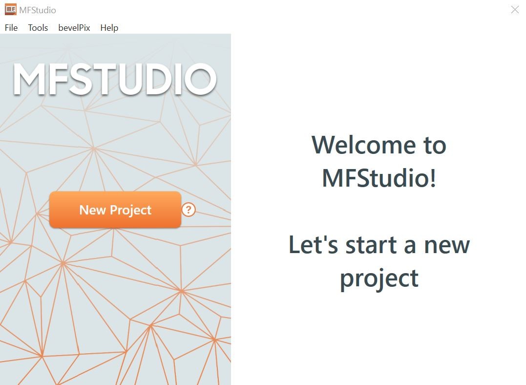
First I calibrated the scanner using a calibration card.
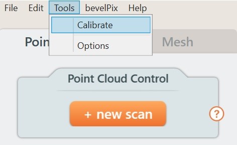
I clicked new scan
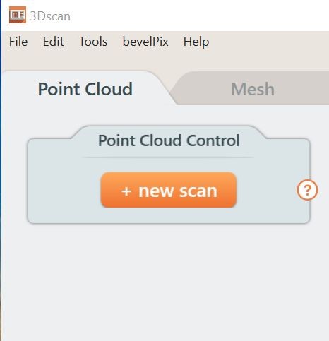
and chose Regular scan. I adjusted Geometry Settings so that I found the sharpest, least fuzzy, laser line and Texture Settings so that object’s colors appear realistic. When I was happy with the settings I clicked Scan.
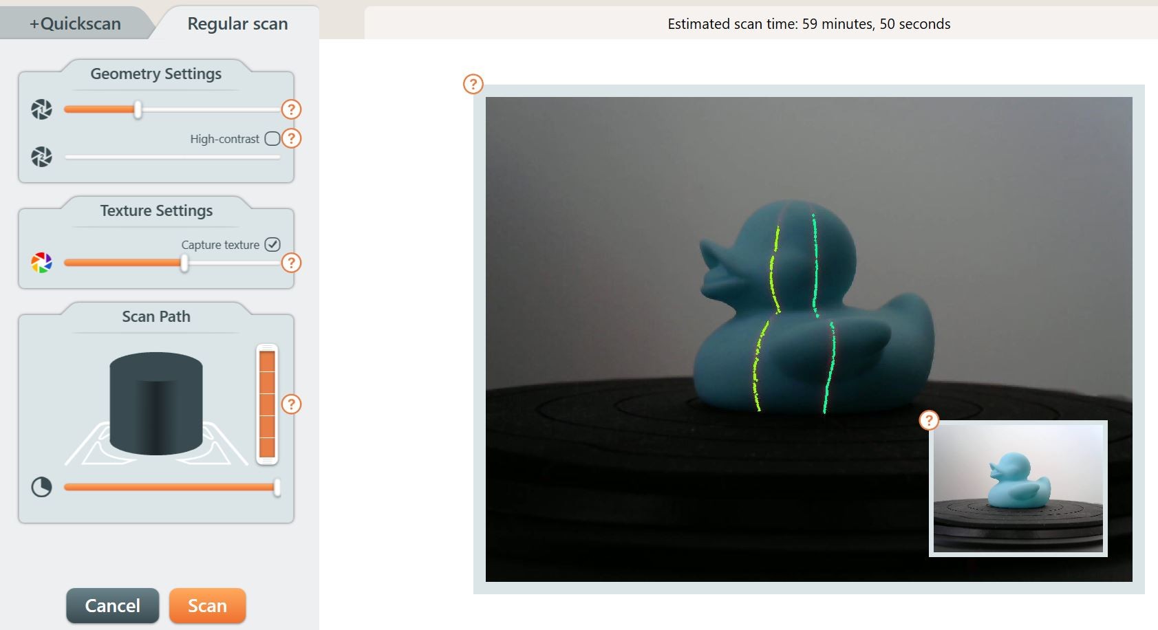
The scan took 59 minutes and the end result was Point Cloud that looked fairly good.
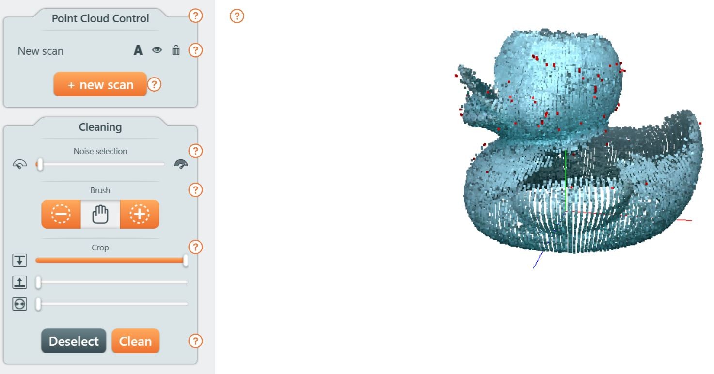
I cleaned extra points with Noise selection tool and created a mesh in Mesh tab.
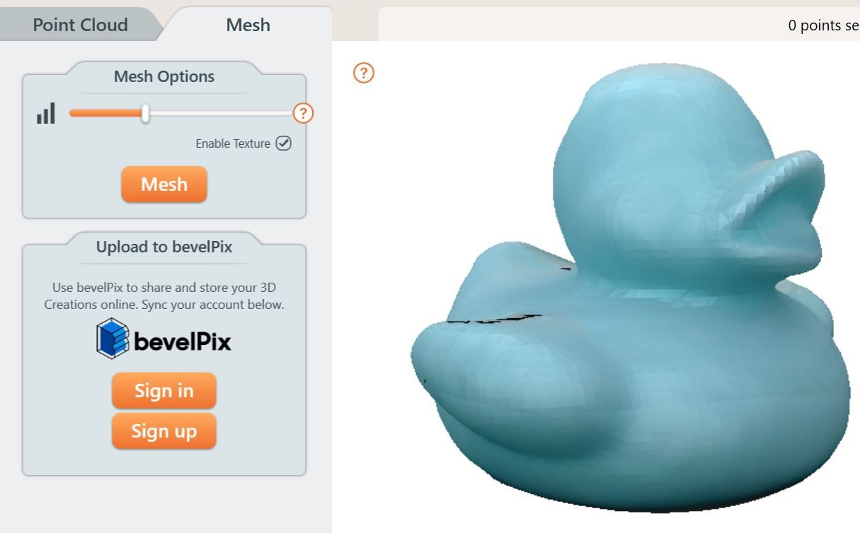
The end result looked so nice that I decided to print it the same way as the box. I scaled it to 75% and set printing temperature to 225°C. The printed object looked surprisingly same as the original object.

Reflection
I learned how to use many new tools in Fusion 360 and also about the limitations in 3D printing. I’m surprised how good end result I got with 3D scanner since I thought the surface would be much rougher.
Overall I think this week was a success since I was able to modify the box so that the hinge worked and got a good end result with 3D scanner.
I didn’t face any major problems since I made the 3D model with help of very informative YouTube video. I’m definitely going to watch Product Design Online’s (person who had made the video I used as a reference) videos also in the future.
The box meets the standard that it cannot be made subtractively. The joint part is made so that upper joint is built layer by layer inside bottom joint. It can’t be made by cutting material away from one piece of material.
Files
Final version of the box (modified snap joint)
3D scanning result