17. Wildcard week
Assignment:
- Design and produce something with a digital fabrication process (incorporating computer-aided design and manufacturing) not covered in another assignment, documenting the requirements that your assignment meets, and including everything necessary to reproduce it. Possibilities include (but are not limited to) composites, textiles, biotechnology, robotics, folding, and cooking.
Desktop robot arm
This week I’m going to test our Mobile Fablab robotic arm uArm Swift Pro. The software used is uArmStudio. I’m going to make a suction head demo that we can use as a simulation for children to show them the idea of how robotic arms in industry work. I’m also using the robot to draw on paper with a pen.
I’m going to test uArm’s learning mode and make a suction cup demo using code blocks. I downloaded the software and worked through manuals to be able to complete the assignment smoothly.
I tried to familiarize myself with uArm’s Blockly coding environment by browsing through code blocks.
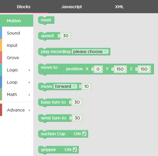
I have an idea of the code I’m using (move to, suction Cup, wait blocks).
Testing suction cup
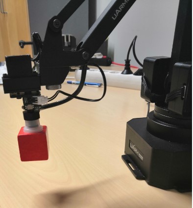
I connected uArm to my computer and opened uArm Studio. In started to test how the code moves the robot arm and how the suction cup works. I ended up with loop() structure that moves the red cube between three places.
Part of the code is presented in the next picture. Wait commands are to make the movement look nicer and is not necessary for the functionality.
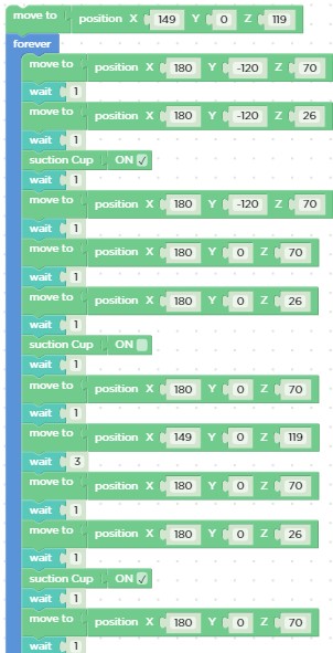
The x, y and z positions are defined in learning mode by moving the suction header to wanted place and the software recognizes the coordinates the header is at and prints the value to “move to” command.
Testing drawing
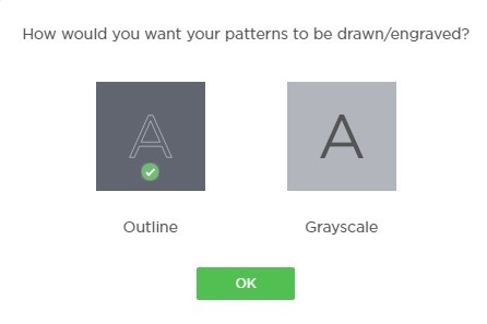
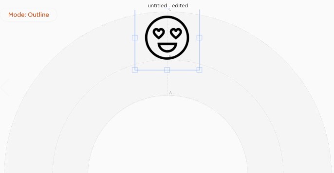
In addition to suction cup test I decided to use a drawing feature in uArmAstudio. I chose outline drawing mode for the drawings.
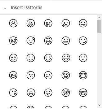
I tested first drawing one pattern from the aArmStudio pattern library. The size of the object can be adjusted from the square around the object.
By clicking “Run” button the robot arm is set to free moving mode, where it can be moved by hand by dragging it to right place and height. I adjusted the zeropoint (height) so that pen just touched the paper. -24 is a height relative to machine original zero point height.
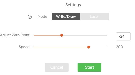
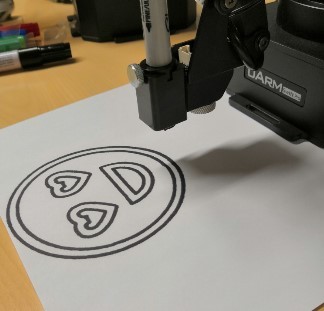
When the pen height was set properly (pen just touches the paper) I hit the “Start” button and uArm started drawing the emoji.
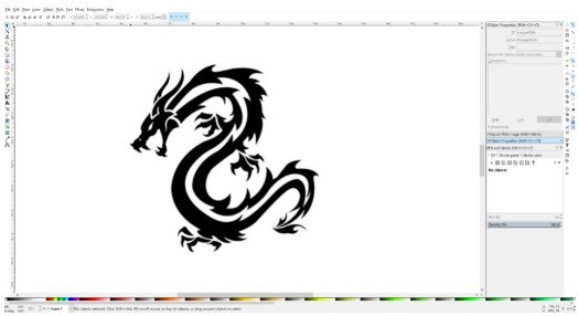
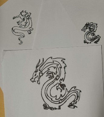
Next I wanted to test the drawing with more complex images and different sized pens. I googled “dragon jpg” and dowloaded a test image to my computer.
I modified the picture using Inkscape.
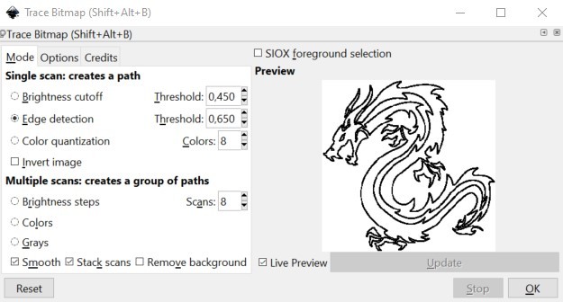
I chose Path >> Trace bitmap and used edge detection.
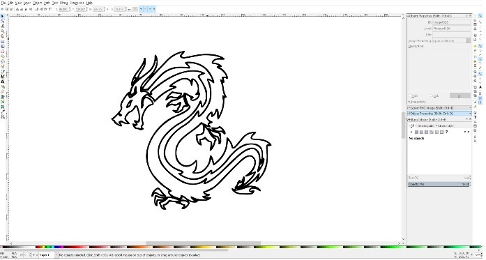
I saved the image as an png since the software didn’t open and svg file. The software probably makes it’s own vector image conversion of png image to define the paths based on Outline/Grayscale selection in the beginning.
I added the picture to uArm Studio drawing board by clicking image button and choosing the downloaded picture.
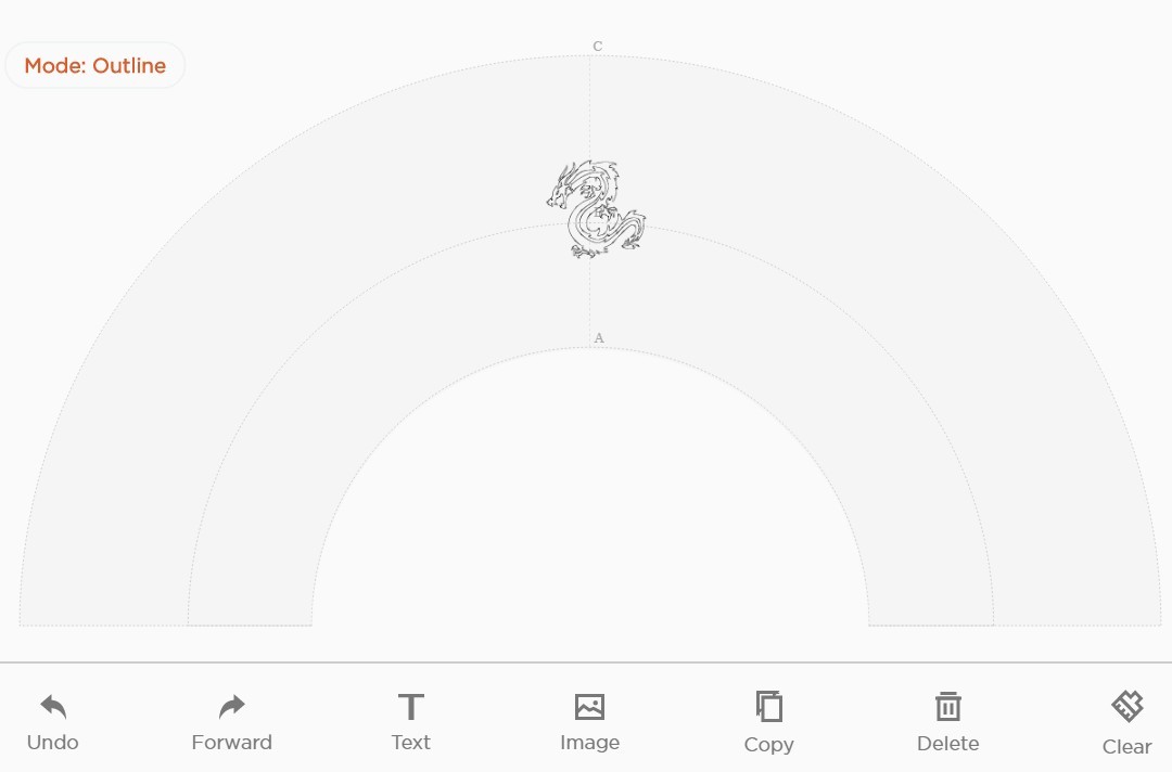
I made three different versions of dragons and they all looked really nice.
Reflection
The coding using blocks is fairly easy and I think we can design a nice workshop using uArm. It could even be a group work where more than one robot takes part on the process. Maybe something similar to automated factory where one robot does one process and “hands” the product to next robot which performs a different action. It could be a good simulation of engineering in real world since the coding works through trial and error and you need good collaboration skills to accomplish this kind of assignment. I got pretty excited about this idea and I’m definitely taking it into a futher development with our Mobile Fablab team.
Also the drawing feature can be used for example by combinig it with laser cutting. We could cut cardboard with laser cutter and draw something on them.
I didn’t face any major issues this week. The blocky coding and learning mode were really easy to use. At first the box that I moved with suction cup did move when it was released from the arm to the table. I did fix that by lifting the arm straight up after releasing the box (insted of an incline towards the base of the machine). Coding was pretty much trial and error kind of process, but without any major things to resolve. In the drawing mode I did first try to add and svg file to drawing board but the software did not accept that file form. It worked when I used png image made from the svg file.