Final Project
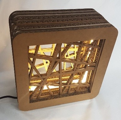
My final project is a lamp with ultrasonic distance sensor. The lamp has Neopixel strip inside. The colour of Neopixel light is controlled by ultrasonic sensor data; lamp colour is light pink when sensor doesn’t detect anything within 1,5 m distance but closer than that the colour starts to turn deeper red.
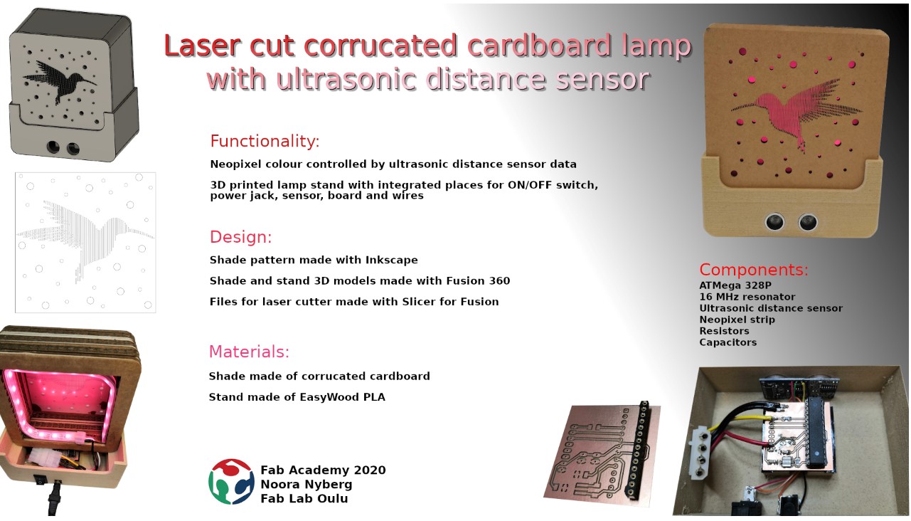
The goal is that in the future we can utilize this project with our Mobile Fablab. Students could design their own lamp shade with Inkscape for example according to given dimensions. Or alternatively they could use a picture and make some modifications on that. Depending on the time available for the whole process student could also design the lamp stand. The coding part could also be a part of the project; the lamp could be controlled by a sensor data or a slide switch for example.
I browsed internet to find some ideas for my final project. The lamp is inspired by Marjo’s lamp shade design and manufacturing process combined with the design of this lamp. Lamp stand is inspired by Alok’s lamp base design. Lamp functionality is inspired by Elena’s idea of using distance sensor to control the lamp.
Processes used for the final project are 2D and 3D design, laser cutting, 3D printing, electronics design, milling and soldering and embedded programming. I’m going to make the lamp shade with laser cutter and the lamp stand with 3D printer. The lamp stand will have integrated places for PCB, ultrasonic sensor, on/off switch and power jack. I’ll keep the design fairly simple to make it possible to use the same principles in the Mobile Fablab workshop.
Lamp shade and stand
Shade pattern
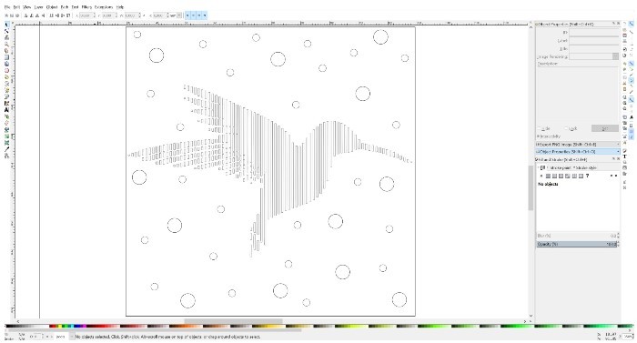
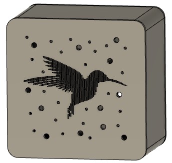
I downloaded humming bird vector image from pixabay. I opened it in Inkscape and added small cirles and 10x10cm frame to it.
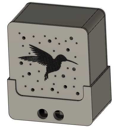
Shade 3D model
I made shade 3D model with Fusion 360. Same principles were used as on (week 6).
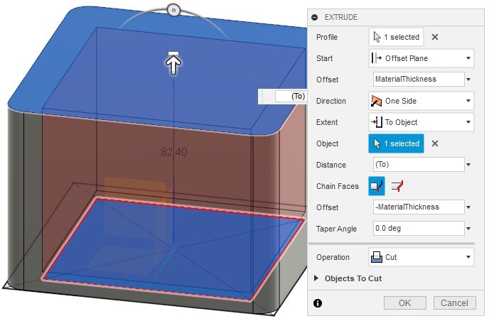
I inserted svg shade pattern on the front plane of the lamp shade body and extruded it to make a cut. I made it a pattern to have it also on the back side of the lamp.
Laser cutter pdf files
I used Slicer for Fusion to make the pdf files. I chose stacked structure with cardboard material thickness.
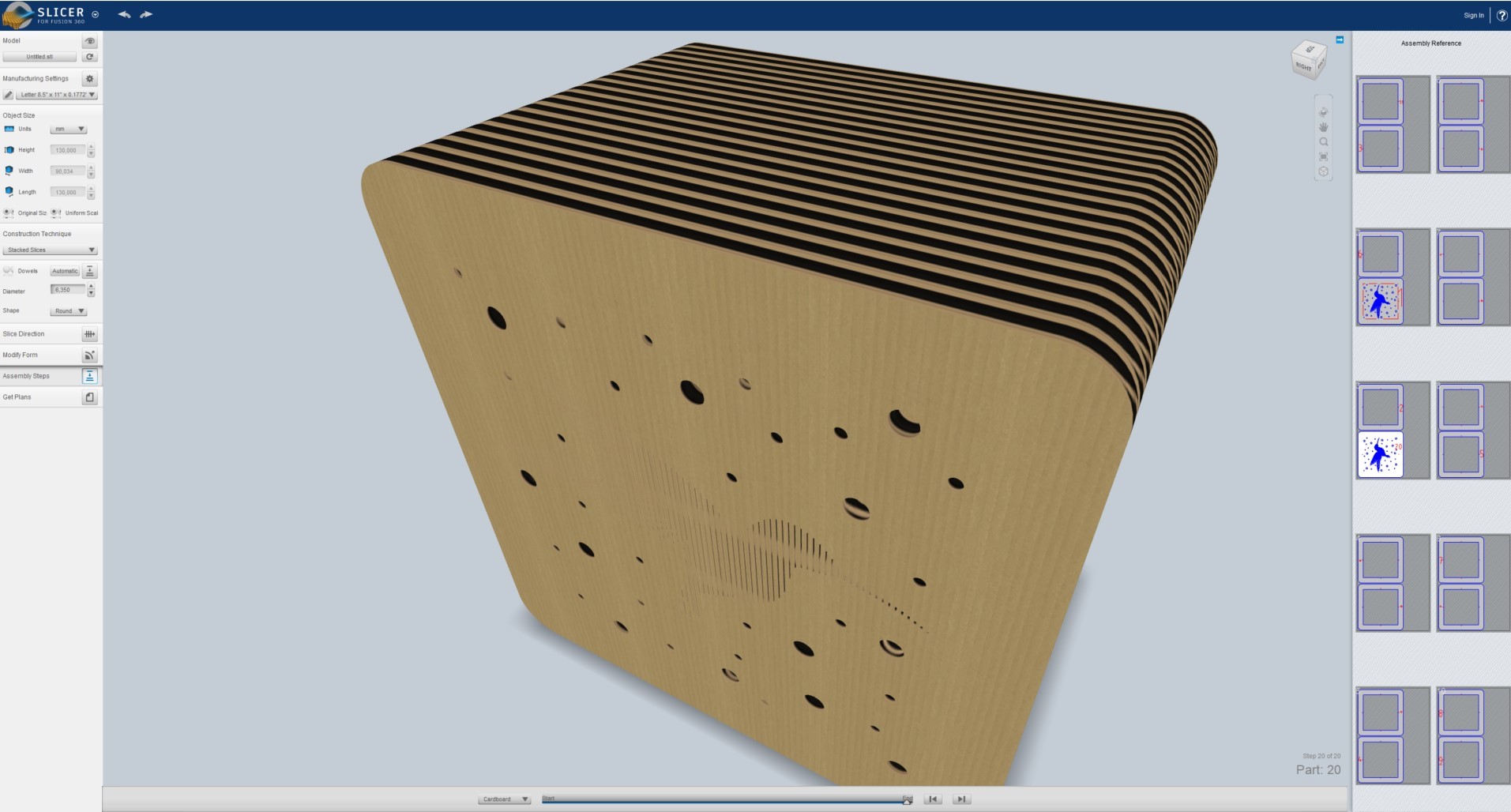
I exported sliced structure as pdf.
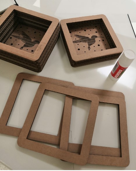
Laser cutting
I used our Mobile Fablab laser cutter to see how well it cuts these parts. The sofware used was LightBurn.
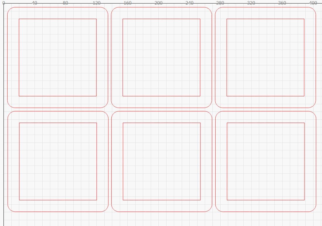
I opened pdf files in LightBurn and arranged them so that I was able to cut as many parts at once as possible.
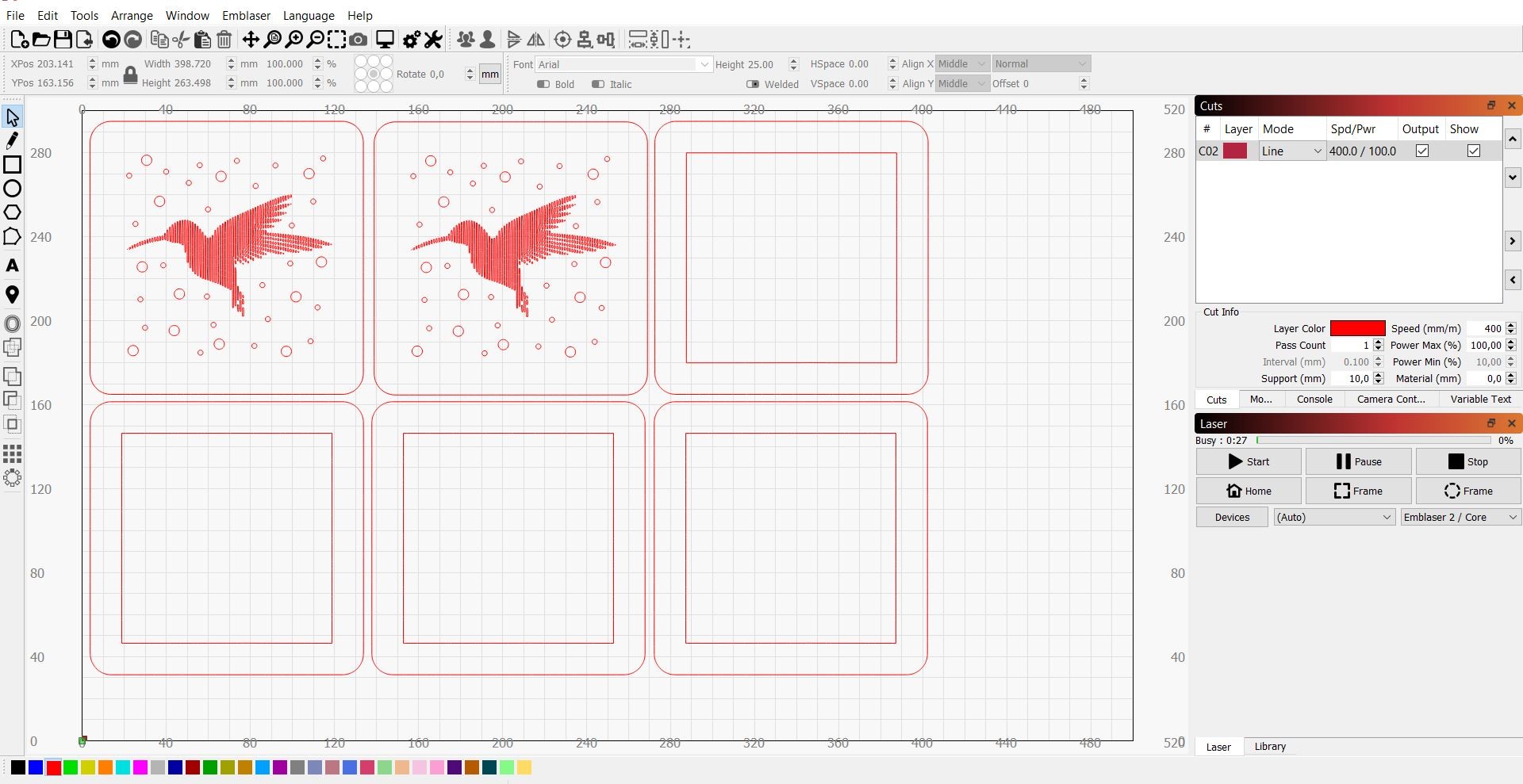
430 mm/min cutting speed did a nice job.
I used glue to stack the slices.
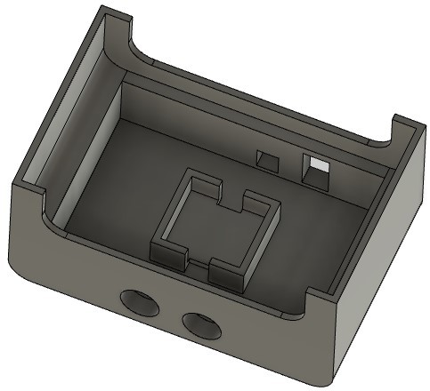
Stand 3D model
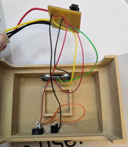
I built the stand model around the shade model in Fusion 360 to make them fit together. I designed holes for ultrasonic distance sensor, on/off switch and power jack and a place for wires to not have a wire mess inside the stand.
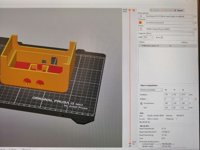
3D printing
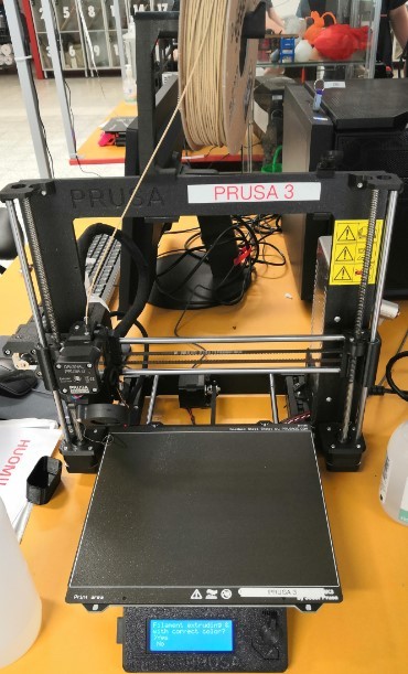
I used Prusa Slicer to make the gcode from stl file for 3D printer. I set layer height to 0.2mm and used Formfutura EasyWood printing profile since I wanted to use EasyWood filament to have same kind of look between cardboard shade and stand. The printer used was Prusa I3 MK3S 3D Printer.
Electronics
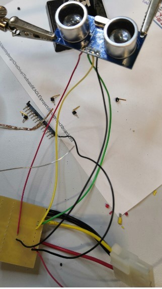
As an input (week 10) the lamp has ultrasonic distance sensor. The output (week 12) is controlling the neopixel strip. All electronics are embedded in a single board.
Tinkercad simulation
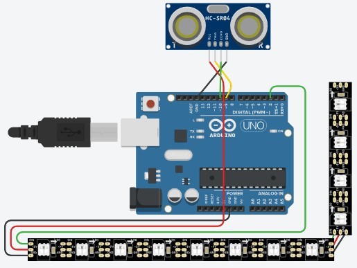
I’m desining my board based on Arduino board. First, I tested ultrasonic - neopixel wiring and code with Tinkercad.
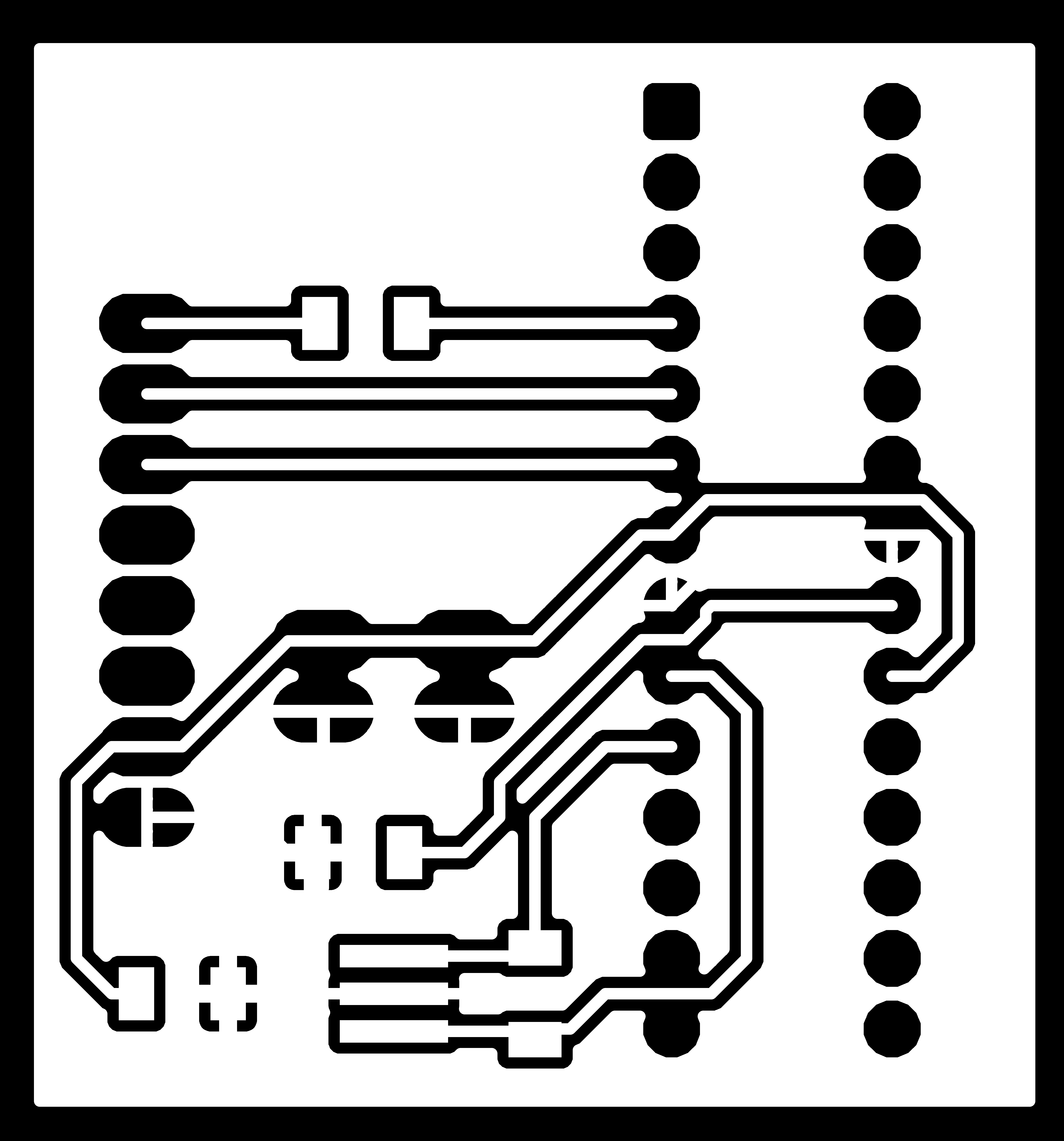
Eagle schematics and board design
Electronics design is made using Eagle schematics and board design. The 8 pin connector is going to be connected to on/off switch with wires and the switch is connected to power jack. Both on/off switch and power jack have their place in the lamp stand.
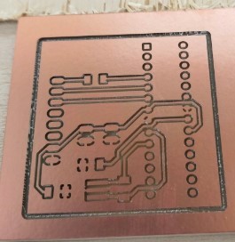
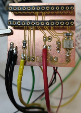
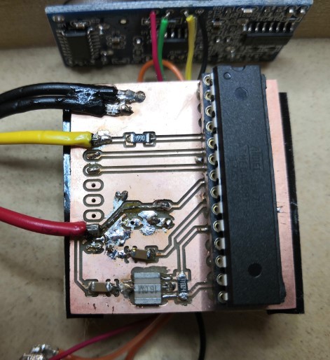
Circuit board was milled and components were then soldered to it. The ATMega chip was programmed using Arduino board and Arduino IDE. In the code ultrasonic distance sensor data is mapped to control the neopixel colour based on the data received. The closer the sensed object is, the brighter red the light is going to be.
Milling and soldering
I used FlatCAM to make the gcode for our Excitech CNC router’s. I exported .gbr and .xln files from Eagle and opened them in FlatCAM.
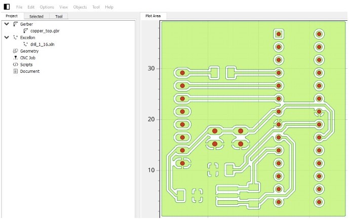
I used V-milling bit (V-tip dia 0.3 mm, V-tip Angle 10° and Cut Z -0.1 mm) to mill the traces and outline profile and 0.7mm tool to drill through board holes.
The process with milling machine was exactly the same as in Computer controlled machining week.
I made a connector for neopixel wiring to make the final assembly of the lamp easier.
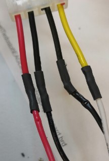
I connected smaller wires from bottom of the board to have them pointing to the wire box in my lamp stand.
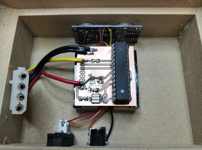
Neopixel wires were very thick and I had some problems soldering them. I finally ended up making a jump wire to have power connected close to side of the board and soldered gnd wires to board ground.
Coding
After some problem solving and modifications to the code (explained more in details in output (week 12)) I ended up with the following code that did the job as I wanted.
#include <Adafruit_NeoPixel.h>
#ifdef __AVR__
  #include <avr/power.h>
#endif

// Which pin on the Arduino is connected to the NeoPixels?
// On a Trinket or Gemma we suggest changing this to 1
#define PIN            2

// How many NeoPixels are attached to the Arduino?
#define NUMPIXELS      20

// defines ultrasonic pins numbers
const int trigPin = 3;
const int echoPin = 4;

// defines variables
long duration;
int distance;
int ledValue;

// When we setup the NeoPixel library, we tell it how many pixels, and which pin to use to send signals.
// Note that for older NeoPixel strips you might need to change the third parameter--see the strandtest
// example for more information on possible values.
Adafruit_NeoPixel pixels = Adafruit_NeoPixel(NUMPIXELS, PIN, NEO_RGBW + NEO_KHZ800);

int delayval = 83; // delay for half a second

void setup()
{
  pinMode(trigPin, OUTPUT); // Sets the trigPin as an Output
  pinMode(echoPin, INPUT); // Sets the echoPin as an Input
  Serial.begin(9600); // Starts the serial communication
  pixels.begin(); // This initializes the NeoPixel library.
  pinMode(2, OUTPUT);
}

void loop()
{
  // Clears the trigPin
  digitalWrite(trigPin, LOW);
  delayMicroseconds(2);

  // Sets the trigPin on HIGH state for 10 micro seconds
  digitalWrite(trigPin, HIGH);
  delayMicroseconds(10);
  digitalWrite(trigPin, LOW);

  // Reads the echoPin, returns the sound wave travel time in microseconds
  duration = pulseIn(echoPin, HIGH);

  // Calculating the distance
  distance = duration*0.034/2;

   // map the sensor reading to a range for the LED
  ledValue = map(distance, 0, 150, 0, 255);
  if (ledValue < 0) {
    ledValue = 0;
  }
  digitalWrite(2, ledValue);

  // Prints the distance on the Serial Monitor to know its range
  Serial.print("Distance: ");
  Serial.println(distance);

  // Prints the LED value on the Serial Monitor to know its range
  Serial.print("LED Value: ");
  Serial.println(ledValue);


  for(int i=0;i<NUMPIXELS;i++){

    // pixels.Color takes RGB values, from 0,0,0 up to 255,255,255
    pixels.setPixelColor(i, pixels.Color(ledValue,255,ledValue)); // Colour based sensor value.

    pixels.show(); // This sends the updated pixel color to the hardware.
    pixels.show(); // This sends the updated pixel color to the hardware.

    delay(delayval); // Delay for a period of time (in milliseconds).

   // For a set of NeoPixels the first NeoPixel is 0, second is 1, all the way up to the count of pixels minus one.

  }
}
I tested the board one more time before the full assembly and it seemed like I was able to stack all the parts together without breaking anything. Success!!
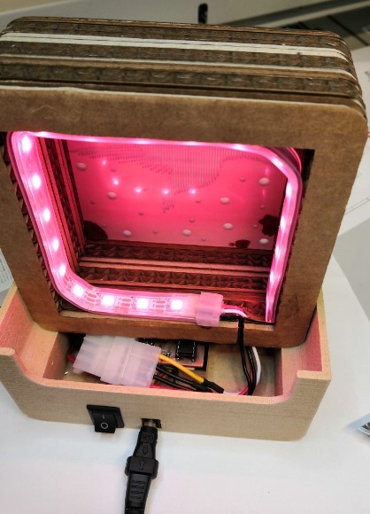
Now finally I have my project ready! (Red light does not show the same way in the video that it does in reality, but the principle of the functionality can be seen)
Materials
I used cardboard for the shade. Our Mobile Fablab lasers are not that powerful so it is more efficient to use cardboard than other materials. The lamp stand is going to be printed using PLA.
Components that I needed for the electronics are ATMEGA328P-PU microcontroller, resonator, resistors, capacitors, spring strain, power jack and Neopixel strip.
The exact components used for circuit board are
-
ATMEGA328P-PU
-
28 pin socket
-
XTAL_RESONATOR_16MHz
-
Ultrasonic distance sensor
-
Resistor 1 MΩ
-
Resistor 470 Ω
-
Capacitor 2 x 100 nF
Basic electronics components are from Fab Inventory. I used components available in our Fab Lab in Tampere.
Materials used are cardboard and EasyWood PLA. Those materials are available in our lab.
Electronics:
Board
| Qty | Description | Price | Pcs | Total |
|---|---|---|---|---|
| 1 | ATMEGA328P-PU | 1.89 € | 1 | 1.89 € |
| 1 | 28 pin socket | 0.90 € | 1 | 1.50 € |
| 1 | resonator | 0.49 € | 1 | 0.49 € |
| 1 | capacitor | 0.10 € | 2 | 0.20 € |
| 1 | resistors | 0.01 € | 2 | 0.02 € |
| 1 | ultrasonic sensor | 5.20 € | 1 | 5.20 € |
| 1 | PCB board | 0.70 € | 1 | 0.70 € |
| total | 10.00 € |
Other:
| Qty | Description | Price | Pcs | Total |
|---|---|---|---|---|
| 1 | cardboard | 0.10 € | 1 | 0.10 € |
| 1 | PLA | 2.00 € | 1 | 2.00 € |
| 1 | Neopixel strip | 5.00 € | 1 | 5.00 € |
| 1 | power jack | 1.47 € | 1 | 1.47 € |
| 1 | power supply | 7.95 € | 1 | 7.95 € |
| total | 16.52 € |
All parts make a total cost of 26.52 €.
Dissemination plan
The product of the final project is not going to be commercial since we are going to utilize this project in our Mobile Fablab. The goal is to implement the idea of designing and fabricating a customized laser cut lamp shade into our workshops. The workshop could also include electronics production in addition to the design process.
License
Since the idea of my final project is to promote learning of digital fabrication processes I want to let others use my work for non-commercial purposes. Hence I’m choosing Creative Commons with ShareAlike and NonCommercial licenses.
Creative Commons license: one of several public copyright licenses that enable the free distribution of an otherwise copyrighted work. A CC license is used when an author wants to give other people the right to share, use, and build upon a work that the author have created.
ShareAlike: If you remix, transform, or build upon the material, you must distribute your contributions under the same license as the original
NonCommercial: You may not use the material for commercial purposes