9. Embedded programming
Group assignment:
- Compare the performance and development workflows for other architectures
Individual assignment:
-
Read a microcontroller data sheet
-
Program your board to do something, with as many different programming languages and programming environments as possible
Group assignment
Our group assignment can be found here
Individual assignment
ATtiny212/412 microcontroller data sheet
I used ATtiny412 microcontroller in my week 7 board. I started this week’s assignment by reading the ATtiny212/412 microcontroller data sheet. The ATtiny412 microcontroller is using the AVR® RISC architecture, and is capable of running at up to 20MHz. It has 4KB Flash, 256bytes of SRAM and 128bytes of EEPROM in a 8- pin package.
The pinout of ATtiny412 is
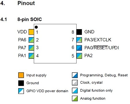
What needs to be taken into account is that the ATtiny412 pinout differs from Arduino IDE megaTinyCore pinout, which is
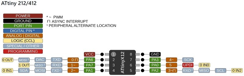
We must follow this pinout in our system. By following ANALOG/Digital pin numbers the LED pin number is 1 and Button pin number is 0.
The ATtiny412 microcontroller system has Single Pin Unified Program Debug Interface (UPDI). UPDI is an proprietary interface for external programming and on-chip debugging of a device. Programming and debugging is done through the UPDI Physical interface (UPDI PHY), which is a 1-wire UART based half-duplex interface using the RESET pin for data reception and transmission. We made UPDI programmer on week 5 that is this week used to program my week 7 board.
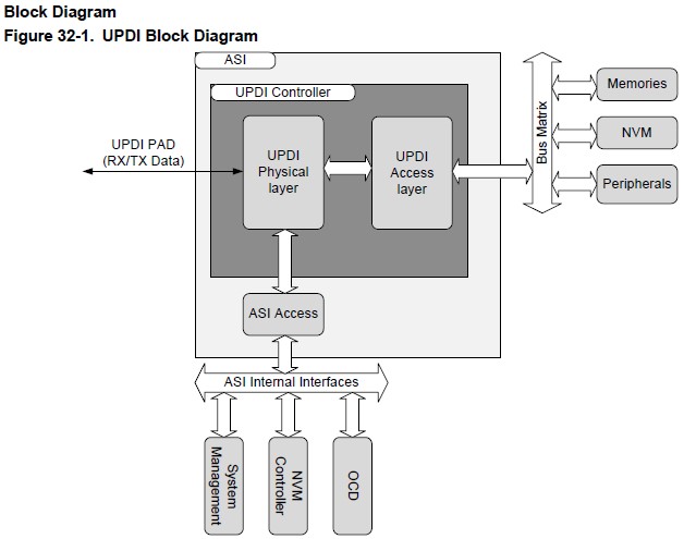
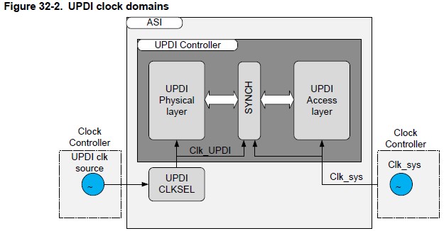
Communication through the UPDI is based on standard UART (universal asynchronous receiver/transmitter)communication, using a fixed frame format, and automatic baud rate detection for clock and data recovery. Communication is initiated from the master (debugger) side, and every transmission must start with a SYNCH character upon which the UPDI can recover the transmission baud rate, and store this setting for the coming data.
Now that I have browsed through the data sheet I feel like I understand better how ATTiny 412 microcontoller works and how to define pin numbers. When I made my programmer on week 5 I felt like I had no idea what I’m doing but now it feels like I understand my programmer better also. Previously I didn’t have any idea what and UPDI even means not to mention how it works.
Tinkercad simulation
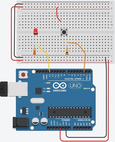
I used Tinkercad to simulate Arduino board with pushbutton.
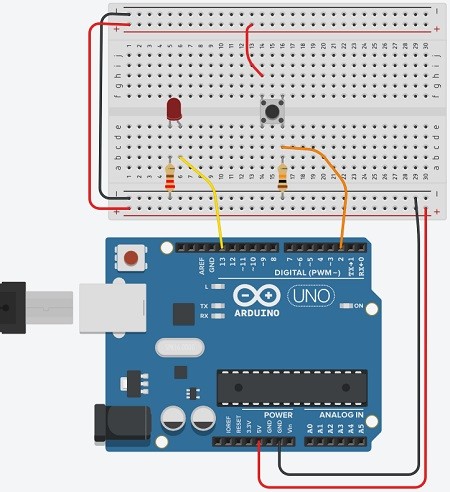
Breadboard power (+) and groud (-) rails are connected to Arduino 5V and ground respectively. Power and ground rails are extended to their respective buses on the opposite edge of the breadboard.
LED is plugged into two different rows so that negative cathode (shorter leg) connects to one leg of a 220 ohm resistor. Other resistor leg is connected to ground. LED’s positive anode (longer leg) is wired up to Arduino pin 13.
Pushbutton is placed across the center column break so that its legs are plugged into four different breadboard rows. One button leg (top left) is connected to power. Diagonally opposite leg (bottom right) is connected to Arduino digital pin 2. That same button leg is connected to ground using 10k ohm resistor.
When the button is pressed, the switch leads are connected, which allows pin 2 to be connected to 5V power with no resistor. Since electricity takes the path of least resistance, the pin will sense the connection to power strongly and ignore the weak 10K connection to ground.
The LED is light up based on the pushbutton’s state: when button is pressed the LED lights up and it shuts down when the button is released.
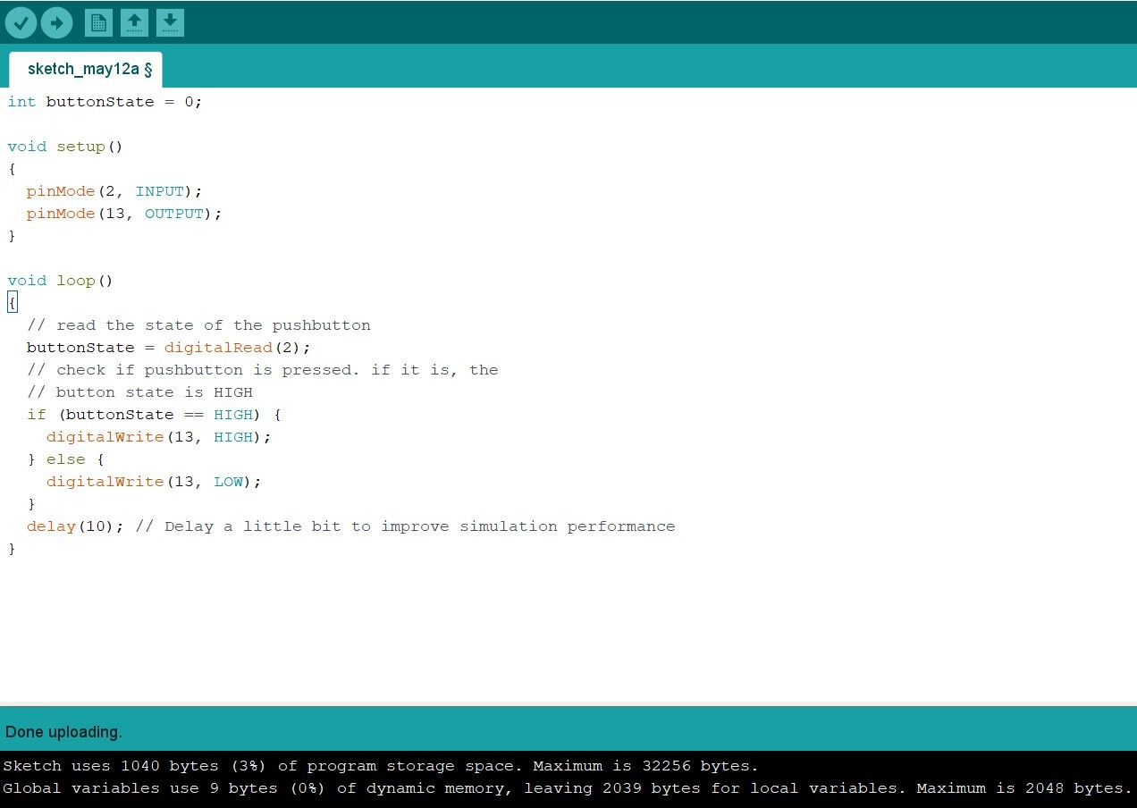
The Arduino code for controlling the pushbutton system from Tinkercad:
int buttonState = 0;

void setup()
{
  pinMode(2, INPUT);
  pinMode(13, OUTPUT);
}

void loop()
{
  // read the state of the pushbutton
  buttonState = digitalRead(2);
  // check if pushbutton is pressed. if it is, the
  // button state is HIGH
  if (buttonState == HIGH) {
    digitalWrite(13, HIGH);
  } else {
    digitalWrite(13, LOW);
  }
  delay(10); // Delay a little bit to improve simulation performance
}
Variable int is created to store the current state of the button.
Inside the setup, pins are configured using pinMode() function. Pin 2
is configured as an input to figure out the electrical state of the pushbutton.
Pin 13 is configired as an output to control the LED.
In the main loop function digitalRead() checks the state of pin 2.
The state is either 5V (HIGH) or ground (LOW). That state is stored in the buttonState
variable.
An if statement checks to see if buttonState is HIGH. If the condition
is met, the built-in LED is set HIGH (on). If not, the code contained inside
the else{ is executed insted: the built-in LED is set LOW (off).
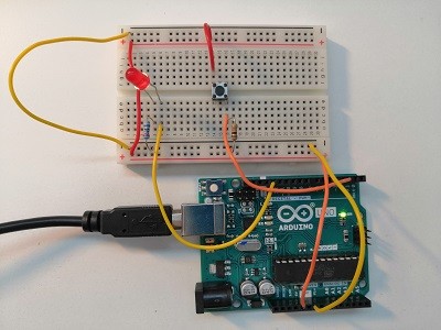
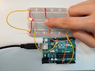
I built the Arduino board and tested if it works the same as in Tinkercad. I copied the code from Tinkercad into an empty sketch in Arduino software and uploaded it to my Arduino board.
The LED light up when the button is pressed.
Programming the board
I tested the code that I used in Tinkercad simulation with my own board. I opened Arduino IDE and chose from tools tab
-
Board: ATTiny 412/402/212/202
-
Port: COM4 (in my computer)
-
Programmer: jtag2updi(megaTinyCore)
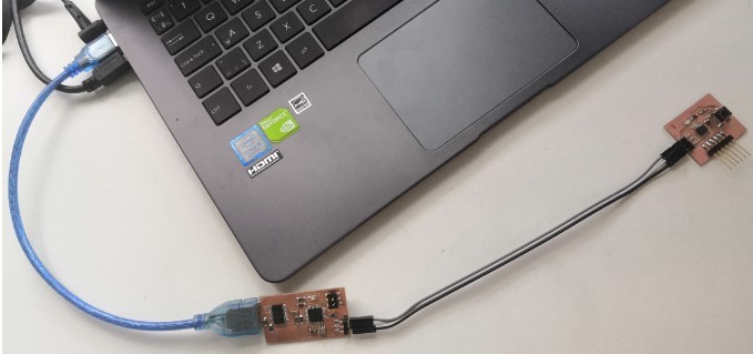
Next I connected my programmer to my week 7 board and to my computer.
I changed pin numbers to mach my board (LED pin is 1 and button pin is 0) and uploaded the code to my board. I had to change
  if (buttonState == HIGH) {
    digitalWrite(13, HIGH);
  } else {
    digitalWrite(13, LOW);
to following
  if (buttonState == HIGH) {
    digitalWrite(1, LOW);
  } else {
    digitalWrite(1, HIGH);
to have the LED turned off when button is not pressed. I did try the original code first but it worked in the opposite way than I expected; LED was burning all the time except when the button was pressed. I was able to make it work the way I wanted by reading Marjo’s documentation.
The code that worked was following
int buttonState = 0;

void setup()
{
  pinMode(0, INPUT);
  pinMode(1, OUTPUT);
}

void loop()
{
  // read the state of the pushbutton
  buttonState = digitalRead(0);
  // check if pushbutton is pressed. if it is, the
  // button state is HIGH
  if (buttonState == HIGH) {
    digitalWrite(1, LOW);
  } else {
    digitalWrite(1, HIGH);
  }
  delay(10); // Delay a little bit to improve simulation performance
}
With this simple code the board is working nicely.
Reflection
After figuring out the pin order of my board the rest was easy. I was able to use the same code that I had used in Tinkercad simulation with small modifications and that code functionality was well explained in Tinkercad. The ATtiny412 datasheet helped me to understand what I needed to do.