16. Molding and casting
Group assignment:
- Review the safety data sheets for each of your molding and casting materials, then make and compare test casts with each of them
Individual assignment:
- Design a mold around the stock and tooling that you’ll be using, mill it (rough cut + (at least) three-axis finish cut), and use it to cast parts
Group assignment
Our group assignment can be found here.
Individual assignment
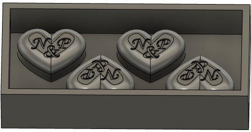
I decided to make a piece of confectionery mold. I used Fusion 360 for designing the mold.
3D design
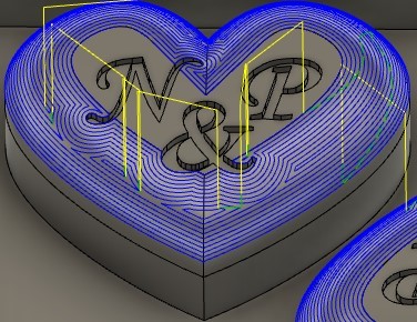
Using Fit Point Spline I created a half of a heart and mirrored it to make a whole heart. I extruded the sketch to 15 mm and used fillet tool to round the top edges of the heart.
I added letters N, & and P to the sketch and extruded them from the top plane of the heart to -2mm thickness. I made three copies of the heart to have four piece of confectionery in one mold.
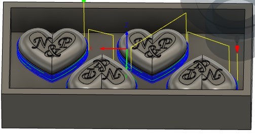
I created my wax block sized rectangle sketch on the bottom plane of the hearts to make a mold shell. I extruded a new body 10mm downwards from the bottom plane. I extruded another body from the bottom of the body that I had just created to 35 mm thickness and deleted the first mold shell body. I used Shell tool with 10 mm Inside Thickness to complete the shell.
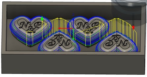
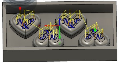
Toolpaths
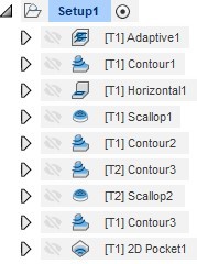
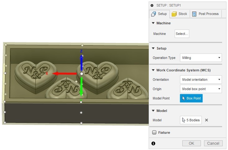
I ended up with following setup
Tools used
-
5 mm flat end (Adaptive1, Contour1, Horizontal1, Scallop1)
-
2.5 mm ball end (Contour2)
-
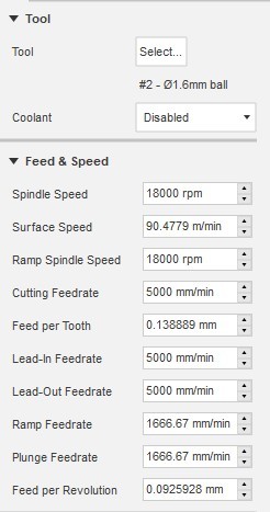
1.6 mm ball end (Contour3, Scallop2)
-
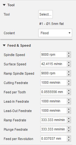
1.5 mm flat end (Contour4)
-
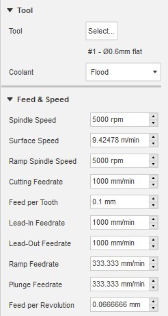
0.6 mm flat end (2D Pocket1)
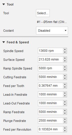
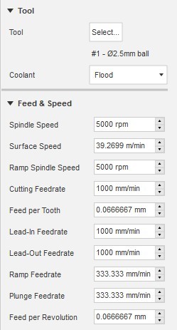
Tool Feed and Speed Setting
Next I describe more in details how I created the toolpath setup.
Step 1
I changed from Design Workspace to Manufacture Workspace to make the toolpaths for milling.
I started the same way as in the computer controlled machining week by creating a new setup with 3 mm Stock Side Offset.
Step 2
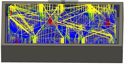
Next I chose Adaptive clearing from 3D tools to clear large guantity of material effectively with 1 mm Radial Stock to Leave. The tool used was 5 mm diameter flat end tool.
I right clicked on the Adaptive Setup and chose Simulate to check if the toolpath looked ok. It did not. The simulation showed that it milled everything away from the inside of the shell, including the hearts. I used a whole day trying to figure out what was wrong and finally I realized that I hadn’t chosen any bodies to model in the setup… After choosing all the bodies from my mold (hearts and shell) I was able to create the toolpath right.
Step 3
Next I chose a 3D Contour to finish mold’s inner sides (no stock to leave). I used the same 5 mm tool.
Step 4
I chose Horizontal toolpath to mill excess material from horizontal plane of the mold. I used again the same 5 mm tool and chose no stock to leave.
Step 5
To clear all material from top of the hearts I used 3D Scallop with the same 5 mm tool.
Step 6
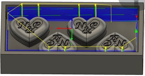
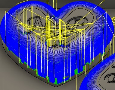
At this point I’m changing the tool to 2.5 mm ball end tool. In this step I’m going to semi-finish the top part of the hearts. I used 3D Contouring and chose hearts’ middle and top chains as a Machining Boundary Selection. I set Maximum Stepdown to 1 mm and Stock to Leave to 0.3 mm .
Step 7
For finishing the hearts’ upper parts I used 3D Contour with 1.6 mm ball end tool. I set Maximum Step Down to 0.1 mm and no stock to leave.
Step 8
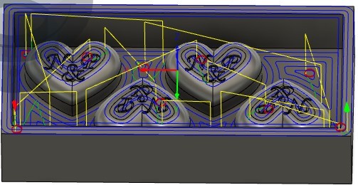
I was not able make the toolpath all the way from the middle plane to the top plane of the heart with 3D Contour. After browsing through different strategies I was able to find strategy that worked: 3D Scallop. First I tried to replace also the previous step with this same strategy but it didn’t make the toolpath all the way down to the middle level of the heart so I decided to keep both strategies.
Step 9
For finishing the lower parts of the hearts I used 3D Contour with 1.5 mm flat end tool. In Geometry tab I chose Model Surfaces (activated inner sides of the shell) and Avoid/Touch Surfaces (activated bottom parts of the hearts and activated Touch Surfaces).
Step 10
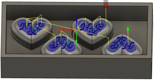
Final part to mill is the letters. Here I used 2D Pocket with 0.6 mm tool. In Geometry tab I chose all letter bottom planes as Pocket Selection.
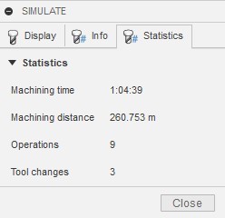
Step 11
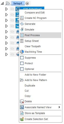
I simulated the whole setup to see work statistics.
I created post process for each TOOL used (all 5mm flat end toolpaths to same gcode etc.) the same way as in week 8.
Milling
Milling was done with Excitech CNC router in Fab Lab Tampere.
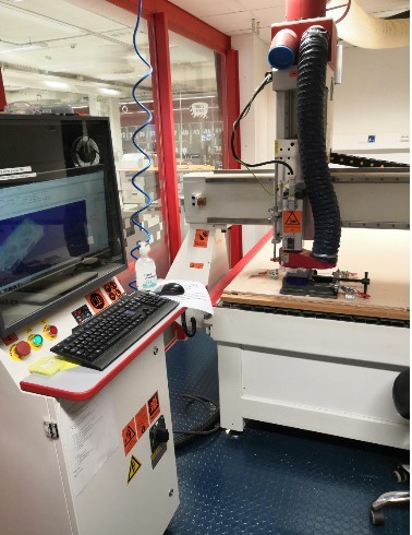
The milling process is described more in details in week 8. I changed milling bits along the milling according to my toolpath setup.
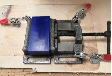
I mounted the Ferris File-A-Wax block (safety data sheet) to router table:
After calibration I started the work. After 5mm flat end tool the work piece looked like this:
After all steps the final mold looked really nice.
Casting
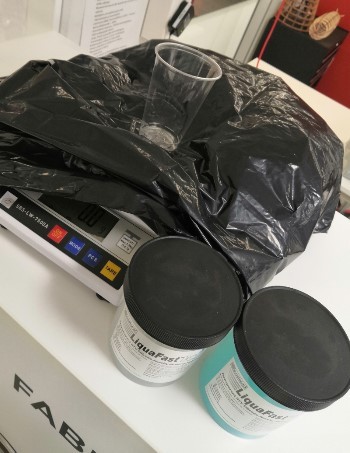
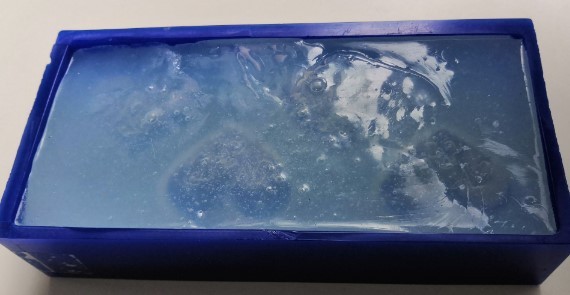
I used LiquaFast Transparent RTV Silicone Jewelry Molding Rubber to make the actual chocolate mold. I read safety data sheet of Part A and Part B. I mixed 100g of Part A and 100g of Part B by stirring the mixture with spoon.
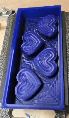
I poured the mixture slowly and steadily to the mold from the corners to prevent forming air bubbles. There were quite a great amount of air bubbles despite of careful pouring but I did tap the mold on the table for quite a long time to move the bubbles upward which seemed to work since in the actual molding part there was no bubbles left (except couple on the letters: I should have started the pouring from there).
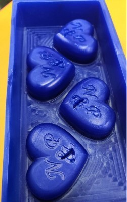
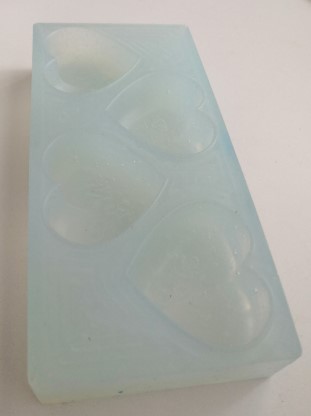
I waited for about 90 minutes to give the silicone enough time to set. After setting I lifted the silicone from the mold using a small screwdriver. I was really pleased with the end result.
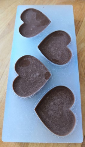
I washed the mold at home and poured chocolate to the it to make some confectionery. I’m happy with the end result!

Reflection
This was quite a laborious assignment since it had so many steps. But it was also a fun week since the end product looked really nice. I’m getting more and more familiar with modeling so that part was quite easy. Figuring out how to make proper toolpaths for this milling took some time. I watched some YouTube videos and asked help from our Fab Lab Tampere laboratory technician and tried different strategies in Fusion to see what works. Finally I managed to make the toolpaths. This week I feel like I really learned how to use the router since I had to do the calibration and tool change more than once.