5. Electronics production
Group assignment:
- Characterize the design rules for your PCB production process
Individual assignment:
- Make an in-circuit programmer by milling and stuffing the PCB and test it
Group assignment
We started the group work by getting familiar with mods by creating the .rml file. After that we used a Roland SRM-20 milling machine to engrave the test pattern on the PCB board.
More about characterizing the design rules for PCB production here.
Individual assignment
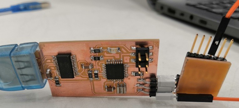
I milled and tested UPDI programmer board that utilizes Arduino IDE to program AVR microcontroller.
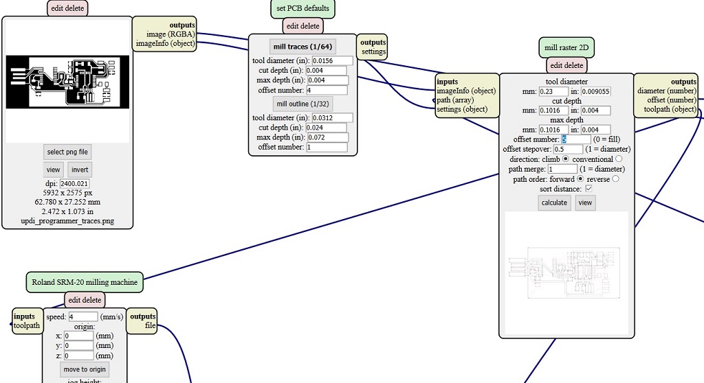
Creating .rml files
I created the .rml files using mods in the same way as we did in group assingment. Only differences were different .png files and inverting the trace file after selecting it. I downloaded calibration, traces and outline .png files from Fablab Oulu’s updi_arduino_programmer GitHub site.


Processing calibration and traces files was done the same way as described in Traces (linetest) in group assignment and outline file the same way as described in Linetest interior. For traces file the tool diameter was set to be 0.23 mm and offset number to be 5.
Milling the board
Calibration of the milling machine was also done the same way as in the group assignment using 0.2-0.5 mm V-milling bit. After calibrating the machine using calibration file I milled the actual board with the same bit. It was a success at first try so I didn’t have to adjust the height of the milling bit and mill again.

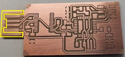
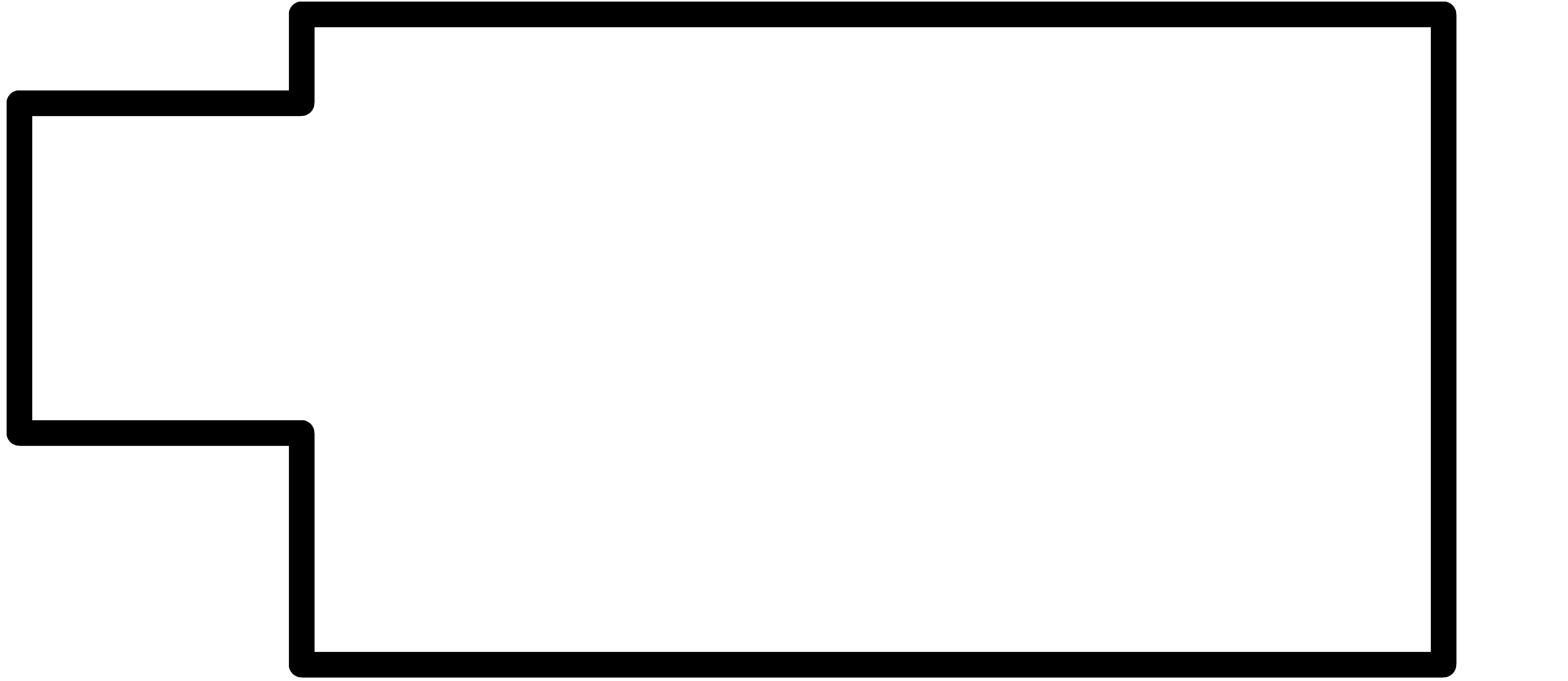
After milling UPDI programmer traces I milled outline using 1.0 mm bit.

After finishing the milling process I used steel wool to remove the photo resist layer from the surface and removed copper parts marked yellow in the picture using a knife.
Soldering
Next thing to do was the most intimidating part: the soldering process. I hadn’t soldered once in my life before this. I got to use microscope and an underlay that Antti (our instructor) had made from mdf to make soldering easier.


Soldering iron was set at 350 Celcius and solder used was tin metal. The soldering was done close to fume extractor since soldering produces harmful vapour.
Components for the board were
-
1x ATmega328P
-
1x FTDI FT231XQ-R
-
1x green led
-
2x 1uF capacitor
-
1x 0.1uF capacitor
-
1x 4.99 kOhm recistor
-
1x 1 kOhm recistor
-
1x 10 kOhm recistor
-
3x 0 Ohm recistor
-
1x 2x3 pin header
-
1x 3RA
It took me a while to get the hang of how to operate with soldering iron and a solder to make a proper joint. But once I found a good touch to it the rest of the soldering process went pretty smoothly even though it took me a while to solder the whole board. In addition to solder the components also USB contacts were covered with tin to prevent oxidation. The tin on USB contacts was flattened using steel wool.
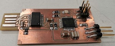
After soldering I added more thickness to board with some extra tape to fit it properly to USB port. The board was also checked with multimeter to make sure there was no short circuit. The multimeter gave a signal of a short circuit so Antti checked my board under a microscope but couldn’t find any unwanted solder bridges. It turned out that there was some residue of the steel wool used to flatten the tin on USB contacts that caused a short circuit. The board was treated with compressed air and checked again with multimeter and now there wasn’t short circuit anymore between VCC and GND.
Programming
The PCB board was connected to computer’s USB port to be powered and to ATtiny microcontroller to be programmed. In Arduino software the process was (done by Antti)
Tools >> Board: Arduino Nano, Processor: ATmega328P (Old bootloader), Port: COM “x”, Programmer: USBtinyISP >> Burn Bootloader (jtag2updi programmer)
The blink test was run to check if programming was done successfully.
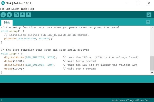
LED was blinking faster when the value was changed and uploaded so the board was working properly as an Arduino board.
Installing the megaTinyCore
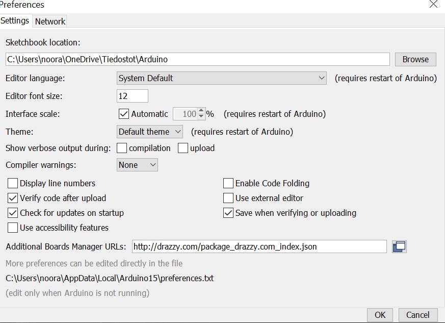
Next I used this instruction to install the megaTinyCore on the Arduino IDE via the Arduino Board Manager. I opened the preferences window and entered “http://drazzy.com/package_drazzy.com_index.json” into the “Additional Board Manager URLs” text box.
Next I opened Arduino board manager: Tools >> Boards >> Boards manager and enetered megaTinyCore into the search bar and installed megaTinyCore by Spence Konde.

I searched also for the “Arduino megaAVR boards” package and installed the most recent version of that too.

The board installation was successful since I was able to see Attiny boards listed under the boards’ section Tools >> Boards.

UPDI programmer
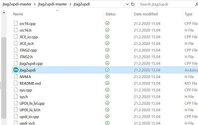
I downloaded and extracted the UPDI programmer sketch. After extracting the download I opened jtag2updi folder. Next I opened the sketch jtag2updi.ino and uploaded it to the Arduino board (an Arduino Nano).

Then in Arduino I selected Tools >> Board: ATtiny412/402/212/202 and Programmer: jtag2updi(megaTinyCore)
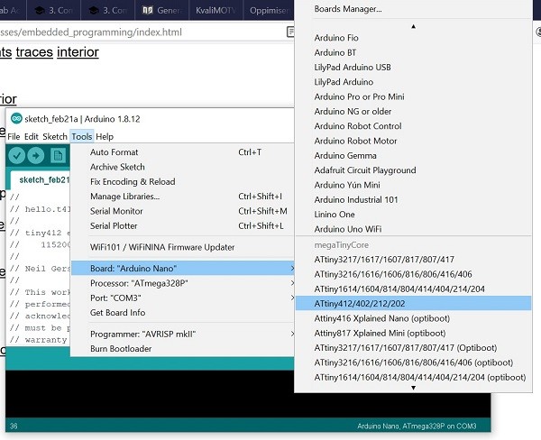

The port to which the Arduino nano was connected was Port: COM3.
Next I hit the upload button and when the upload process was complete the microcontoller performed as programmer.
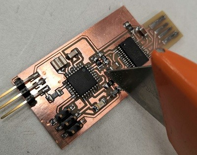
Now that the microcontroller was programmed to be a programmer the connection shown in figure was cut with knife to prevent it to be programmed again.
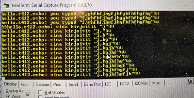
The programmer was checked on Antti’s computer by connecting a board with ATtiny412 to my programmer.

I copied the text from echo.ino and added it to new sketch in Arduino, changed the text “you typed” to “sina kirjoitit” and hit upload.
ATtiny 412 board was then connected to Antti’s computer and it showed that the programming was done successfully.
What I learned
This week everything we did was the first time for me to do it. I learned about milling process; how to make a file for milling taking into account the tool diameter and it’s effect on milling, how to calibrate the tool level and how to run the milling machine.
The programming part was also new to me and I understood the process not until I wrote this documentation. Seems like insted of just being an extra work it helps us to understand what we are doing.
Problems
I was very happy how well everything went this week! Antti was very helpful which made it easy to get everything done. I didn’t face any major problems. The only thing that I struggled with was to understand the programming process but I got the hang of it by glancing through other students’ pages and reading instructions again.